Milling Cutters and Associated Technologies Part 3 potx
Bạn đang xem bản rút gọn của tài liệu. Xem và tải ngay bản đầy đủ của tài liệu tại đây (775.75 KB, 10 trang )
•
Insert wear uneven – possibly resulting from inad-
equate pre-setting of the cutting inserts – allowing
some to ‘stand-proud’ of the rest and as a conse-
quence, being subjected to higher wear than the
others,
•
Insert shape irregularities – possibly the result of
poorly manufactured cutting insert geometries,
creating diering heights once secured and accu-
rately positioned in their respective milling insert
seatings,
•
Irregular chip-ow – possibly the result of either the
insert chip-breakers operating inconsistently, or the
workpiece material having matrix inconsistencies.
4.2 Pocketing, Closed-Angle
Faces, Thin-Walled and
Thin-Based Milling
Strategies
Pocket Milling
In particular and in the aerospace industries, alumin-
ium machining from: wrought, extruded stock and
forged parts is a regular practice and, to a lesser extent,
this also occurs in many precision machining environ-
ments. Oen both for shallow and deep pockets and
for ribs, it is necessary to relieve weight at critical sec-
tions on components.
One of the oldest established techniques for achiev-
ing pocket features, is to drill a hole at the centre of the
pocket to a pre-set depth. en change tools and plac-
ing the milling cutter in this hole clear-out the pocket,
repeating this cycle until the pocket is ‘roughed-out’.
Perhaps changing cutters and taking nishing cuts to
complete the feature (Fig. 87ai). Rather than simply
plunging to depth with the cutter, ramping-down into
pockets is an eective way of reaching the ‘rst-level’
for the pocket’s area clearance. Both ramping and
‘double-ramping’ (i.e. this latter technique is particu-
larly ecient for smaller pocket dimensions), are ways
of removing stock via a ‘diagonal plunge’ , while tak
-
ing the milling cutter to its required depth (Fig. 87aii).
is technique is an ecient machining strategy for
the milling of square and rectangular pockets – for
high stock removal.
If the pocket is of non-uniform dimensions, then
perhaps a ‘lace’ , or ‘non-lace’
26
cutter path clearance
technique might be the preferred option, when having
to machine these type of component features.
Milling Closed-Angle Faces
For the machining of so-called ‘closed angle features’
such as a re-entrant pocket
27
, or ‘dovetail’
28
, these latter
features are typically utilised for drop-forging inserts.
In Fig. 87bi, the pocket has a land (i.e. to impart ad-
ditional mechanical strength to the corner), this land
which would run around the base of the enclosed
pocket, requiring a 5-axis machining centre
29
to com-
plete the milling operation. In Fig. 87bii, a normal end
mill cannot remove the excess material le in the base of
the re-entrant angle, necessitating either a ball-nosed,
or tapered ball-nosed cutter to reach in and mill the
desired feature (Fig. 87biii – in this case, the illustra-
tion shows a tapered ball-nosed milling cutter).
26 ‘Lace’ , or ‘non-lace’ cutter path, a ‘lace-cut’ is where the cutter
clears (i.e. machines) an area with cutter paths that step-over
at regular pre-dened intervals, normally used when a sur-
face has regular dimensions, such as a square, or rectangular
feature. Conversely, a ‘non-lace’ cut is normally reserved for
the machining of irregular surfaces with the tool paths being
non-linear in their step-over paths, for example, when milling
a triangular-shaped pocket/feature, or similar.
NB With the advent of sophisticated Computer-aided Manu-
facture (CAM) programming capabilities, much of the auto-
mated generation of cutter paths, decision-making is under-
taken by the soware, to optimise area clearances for these
component features.
27 ‘Re-entrant pocket’ , is one where the base of the pocketed fea-
ture is somewhat larger than its top, meaning that the pocket
faces slope inward.
28 ‘Dovetails’ , are normally open at both ends allowing the male
dovetail on the part to be held and its tapered key to easily
inserted, positioned and locked in-situ. Usually, such features
are generated and formed on machine tools such as: Plano-
mills, Shapers, etc., but where such equipment is not available,
then a ‘closed-angle milling’ operation is necessary.
29 5-axis Machining Centre, normally has 3 linear (i.e. X, Y and
Z) and 2 rotary (i.e. A and B) axes. e relationship of the
rotary axis will depend upon the machine tool’s congura-
tion, but they allow axis of a milling cutter into an otherwise
closed-feature, negating the possibility of any cutter/spindle
fouling on the workpiece.
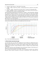
Milling Cutters and Associated Technologies
Milling Thin-Walls
For the machining of thin-walls (Fig. 88), such as
when milling rib-sections on aerospace components,
the machining strategy will vary, depending upon the
respective height and wall thickness. In every case of
thin-walled machining, the number of passes will be
determined by the component’s wall dimensions and
axial depth of cut, in the following manner:
•
Height-to-thickness ratios of <15:1 – then possibly
the most favoured milling strategy is to machine
one side of the wall in non-overlapping passes, fol-
lowed by a repetition on the remaining side – as
depicted in Fig. 88a. In all cases of thin-walled ma-
chining a ‘nishing allowance’ is le on both sides
and the base for subsequent machining,
•
Height-to-thickness ratios of <30:1 – there are two
basic milling techniques that are usually employed,
these are:
•
‘Waterline milling’ (Fig. 88b-le) – this is where
either side of the thin-wall feature is milled to pre-
determined depths, in non-overlapping passes,
Figure 87. Pocket and closed-angle feature milling. [Courtesy of Sandvik Coromant].
Chapter
Figure 88. Thin-walled machining strategies. [Courtesy of Sandvik Coromant].
Milling Cutters and Associated Technologies
•
‘Step-support milling’ (Fig. 88b – right) – this tech-
nique utilises a similar approach to the previous
method, but in this case, there is an overlap between
passes on opposite sides of the wall. is strategy
gives more support at the vicinity where machin-
ing occurs and the cutting forces are less likely to
distort the wall as it height increases.
NB For very large height-to-thickness ratios of
>30:1, an alternative milling strategy, is to alter-
natively mill either side of the wall – approaching
the desired wall thickness in stages in a so-called:
‘Christmas tree routine’
30
(i.e. not shown), so that
the thinner sections are always supported by thicker
sections below them. is method is then repeated
as the step-wise milling operation moves down the
wall.
Milling Thin Bases
Unsupported thin-base features, such as the one il-
lustrated in Fig. 89, are dicult to produce once the
previous side has been machined, because of the lack
of support, particularly at the base’s central region.
One milling approach in the production of this unsup-
ported thin-base, is to ‘helically mill’ the feature (i.e.
shown in cross-section in the small inset diagram in
Fig. 89). is usually necessitates milling at the cen-
tre of the base region, spiralling-down to the required
depth, then milling outward in a ‘attened helical
manner’ from that point (Fig. 89 – main illustration
and plan view). Occasionally, one of the faces has al-
ready been machined and under these conditions it
must be ensured that the cutter’s ank makes minimal
contact with this face, for this operation it is usual to
employ tooling with the minimum number of utes.
Sometimes a component to be thin-based milled,
has a hole at its base’s centre, in such a situation it is
prudent to leave a support leg in place when milling
the rst side. en machine the second side, nally re-
moving (i.e. milling) this support leg aer both sides
have been completed, thereby minimising any base de-
viation due to the presence of the cutting forces whilst
milling the feature.
30 ‘Christmas tree routine’ , is so-called, because as it is being
step-wise milled and progressively develops, the silhouette re-
sembles the prole of the Christmas tree – hence its name.
4.3 Rotary and Frustum-
Based Milling Cutters –
Design and Operation
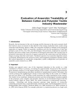
Rotating Insert Face-Mills
One of the novel face-milling cutters which is cur-
rently available includes rotating round inserts that
are self-propelled as they cut (Fig. 90a), promoted by
the chip-ow over the insert’s face. It has been claimed
by the tooling manufacturers of these interchangeable
rotating insert cutters, that their unique cutting ac-
tion provides greater cutting eciency and is less de-
structive to the inserts, than the conventional ‘locked’
milling inserts. e term that is used for this rotating
cutting action is ‘roll shearing’
31
. e rotation of the
inserts continually introduces a ‘fresh’ cutting edge to
the workpiece, this, it is claimed, minimises any heat
build-up in the cutting zone, with much of the heat
being transferred to the milled chips. Any remaining
heat being easily dissipated along the entire length of
these round inserts (i.e. the insert circumference has
an eective total cutting edge length of approximately
85 mm). is rotating insert has an almost
innite ef-
fective cutting edge length, enabling around a 10-to-1
improvement of insert life. Due to the increased tool
life, less down-time for changing cutting edges is re-
quired, thereby improving cutting eciency and im-
pacting on actual overall cycle-times, because faster
cutting speeds
32
can be utilise.
It has further been claimed by the tooling manu-
facturer, that with the very high cutting speeds the lo-
calised heat is of benet, as the heat within the cutting
zone is concentrated in the chip and not in the work-
piece, or the insert. is local heating of the metallic
workpiece, allows it to reach its plastic deformation
stage, causing the chip to ow freely away from the
31 ‘Roll shearing’ , is a combination of the rotating action of the
round cutting inserts, in combination with the angled axis
which slices, or shears through the workpiece.
32 Rotating insert cutting speeds – with these rotary insert cut-
ters has been increased dramatically, when compared to the
more conventional ‘locked insert’ face-mills. For example,
when the silicon nitride cutting inserts are face-milling cast
iron components 1,000 m min
–1
is possible, conversely, when
face-milling aluminium workpieces cutting speeds of 2,300 m
min
–1
have been successfully employed.
Chapter
Figure 89. A strategy for the milling of thin-bases. [Courtesy of Sandvik Coromant].
Milling Cutters and Associated Technologies
Figure 90. A range of rotary milling cutters. [Courtesy of Rotary Technologies Corp.].
Chapter
milled surface. is localised plasticity allows the en-
ergy to be maximised and the cutting eciency to be
increased. Moreover, lower workpiece heat, results in
less component distortion. Yet another benet of this
‘roll shearing’ action, is that when conventional cutters
are used the tangential force component is high and it
is one of the primary causes for spindle bearing wear,
because of the side load it imparts into the spindle’s
bearings. Due to the rotary motion of these inserts,
they minimise tangential forces and as such, reduce
side loads on the machine’s spindle bearings.
Frustum-Based Face-Mills
When compared to some other milling cutter insert
geometries, the round inserts have two advantages:
•
Inherent strength – no sharp edges, minimising
potential points of weakness in the geometry, im-
parting high shock resistance and fracture tough-
ness. Hence, ‘frustums-based’ face mills have up to
10 times longer tool life, in comparison to conven-
tional milling insert geometries,
•
More cutting edges – they can be turned and locked
in their seatings, creating approximately twice as
many cutting edges per insert – giving up to 24 in-
dexes per insert – when compared to conventional
milling inserts.
NB Like conventional insert geometries, normal
round inserts oer the user two choices, whether
to choose a high eciency positive insert, or longer
insert life using a negative geometry round milling
insert.
e frustum-shaped (round) face-milling insert (Fig.
91), has a cutting edge which is reinforced by addi-
tional mass while at the same time oering a 60° posi-
tive shearing action (Fig. 91a). is frustum-designed
insert geometry, eliminates angles and straight lines,
allowing high stock removal rates to be utilised. Typi-
cally, these frustum-based insert designs, when mill-
ing grey cast iron can use peripheral speeds of >700 m
min
–1
at feedrates of 6.4 m min
–1
, whereas, for alu-
minium milling, the surface speed can be increased to
1,650 m min
–1
, but with a feedrate of >8 m min
–1
.
Figure 91. A frustum-based milling cutter. [Courtesy of
Rotary Technologies Corp.]
.
Milling Cutters and Associated Technologies
Figure 92. A range of special tools (i.e. customised), catering for specic company production needs. [Courtesy of Ingersoll].
Chapter
4.4 Customised Milling
Cutter Tooling
Custom-built tooling is as its name implies, oers
quite considerably diverse tool designs (i.e. see Fig.
92 for just ‘snap-shot’ of a small range of these types
of tools). Some of this customised tooling can be rela-
tively simple, perhaps just manufactured to mill only
one particular feature, while others are very complex
and sophisticated in both their design and operation.
Of this latter type are the numerically-controlled, or
‘feed-out’ facing and boring heads (not shown). ese
programmable heads allow the machining of features
such as large bores with intricate proles, typically:
multiple diameters, grooves, tapers and even threads –
on a range of prismatic parts. Until such heads became
available, these workpiece features would have required
the knowledge by either a CNC programmer, or more
likely they would have been ‘routed’ to a conventional
jig-boring machine for a highly-skilled technician
known as a jig-borer to complete the complex machin-
ing task. ese numerically-controlled heads have
a programmable U-axis tool-slide that can be co-or-
dinated to that of the Z-axis, enabling it to produce
tapers and contoured bores, or even outside diameter
features. Once the head is located in the spindle, its
powered tool slide via a compact auxiliary d.c. servo-
drive motor (i.e. being a closed-loop system with feed-
back – to monitor its relative position at all times), will
control the radial motion as it rotates down a bore, or
around the outside diameter of a component.
Tooling can be designed to create virtually any
component feature on a workpiece and, with the
CAD/CAM soware available today, tooling designers
have a vast array of computing power to allow them
to eciently produce customised tooling within very
short lead-times. However, a word of caution here,
these customised tools are not inexpensive and should
only be purchased if the alternative tooling approach
is such, that cycle-times are otherwise lengthy, or there
is simply no other technique that will enable these part
features to be produced at economic cost.
4.5 Mill/Turn Operations
On many hybrid machine tools today, the traditional
operations associated with one particular type of ma-
chine tool, are now being produced on others. Take for
example a turning centre, in the past it would simply
have been employed in the production of workpieces
with rotational features. Now, with the addition of a
turret equipped with live/driven tooling (i.e. rotating
spindles in some, or all of the turret’s pockets), it is
possible to lock the headstock spindle, mill a feature:
at, keyway, gear tooth, or spline, then angular index
the spindle and repeat, until all of the so-called ats
– oen known as ‘prismatic features’ – are completed.
Moreover, it is possible to purchase a ‘mill/turn centre’
with ‘full’ C-axis headstock spindle control giving it
the capability to generate contoured surfaces, or faces
on the previously turned part (i.e. see Fig. 93). is
diversity in the machining operations that can be un-
dertaken by simply one machine tool, means that the
so-called ‘one-hit machining’
33
operations are possible,
thereby reducing the risk of loosing the accurate da-
tum initially set when the part was turned, so increas-
ing production consistency due to its more repeatable
machining precision and accuracy.
Some companies in England and elsewhere, are
now producing rotational features on prismatic parts,
these being produced on machining centres. is un-
usual reversal technique is achieved by tting turning
tools in a suitable xture on the machine tool’s bed
and rotating the part held in a appropriate manner in
the machine’s spindle. Moreover, it is now possible to
not only purchase a machine tool that can: turn, mill,
bore, thread, but it can even cylindrically grind as well
– truly showing the diversity over a range of machin-
ing operational processes.
For further information on the possible problems
that may be encountered in milling operations and the
anticipated solutions, these are given in the Trouble-
shooting Guide for Milling Operations, in Appendix 6.
33 ‘One-hit machining’ , refers machining parts from wrought
stock, etc., in one complete operation.
Milling Cutters and Associated Technologies
Figure 93. Driven/live tooling: milling a spiral groove (top) and face-contouring (bottom) under ‘full’ C-axis control, on a mill/turn
centre. [Courtesy of DMG (UK) Ltd.]
.
Chapter