CRC Press - Mechanical Engineering Handbook- Mechanics Of Solids Part 8 docx
Bạn đang xem bản rút gọn của tài liệu. Xem và tải ngay bản đầy đủ của tài liệu tại đây (35.28 KB, 1 trang )
1-70 Section 1
4.The principal stresses σ
1
and σ
2
are on the σ axis (τ = 0).
5.The planes on which σ
1
and σ
2
act are oriented at 2θ
p
from the planes of σ
x
and σ
y
(respectively)
in the circle and at θ
p
in the element.
6.The stresses on an arbitrary plane can be determined by their σ and τ coordinates from the circle.
These coordinates give magnitudes and signs of the stresses. The physical meaning of +τ vs. –τ
regarding material response is normally not as distinct as +σ vs. –σ (tension vs. compression).
7.To plot the circle, either use the calculated center C coordinate and the radius R, or directly plot
the stress coordinates for two mutually perpendicular planes and draw the circle through the two
points (A and B in Figure 1.5.4) which must be diametrically opposite on the circle.
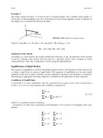
Special Cases of Mohr’s Circles for Plane Stress
See Figures 1.5.5 to 1.5.9
FIGURE 1.5.4Mohr’s circle.
FIGURE 1.5.5Uniaxial tension.
FIGURE 1.5.6Uniaxial compression.
FIGURE 1.5.7Biaxial tension: σ
x
= σ
y
(and similarly for biaxial compression: –σ
x
= –σ
y
).
FIGURE 1.5.8Pure shear.