wdm optical interfaces for future fiber radio systems phần 5 pot
Bạn đang xem bản rút gọn của tài liệu. Xem và tải ngay bản đầy đủ của tài liệu tại đây (369.75 KB, 30 trang )
Chapter 3: WDM Optical Interface for Simplified Antenna Base Stations
signal at DL Drop port and the uplink signal at ADD port, generated by reusing the
recovered optical carrier, were also quantified, which are shown in Fig. 3.20. The
error-free (at a BER of 10
-9
) data recovery and the recovered optical spectra verified
-50
Wavelength relative to 1552.22 (nm)
-30
-10
-0.8 -0.4
00.40.8
Optical Power (dB)
DL Drop
-50
Wavelength relative to 1552.22 (nm)
-30
-10
-0.8 -0.4
00.40.8
Optical Power (dB)
IN to Interface
(a)
(b)
-50
Wavelength relative to 1552.22 (nm)
-30
-10
-0.8 -0.4
00.40.8
Optical Power (dB)
DL Drop
-50
Wavelength relative to 1552.22 (nm)
-30
-10
-0.8 -0.4
00.40.8
Optical Power (dB)
DL Drop
-50
Wavelength relative to 1552.22 (nm)
-30
-10
-0.8 -0.4
00.40.8
Optical Power (dB)
IN to Interface
-50
Wavelength relative to 1552.22 (nm)
-30
-10
-0.8 -0.4
00.40.8
Optical Power (dB)
IN to Interface
(a)
(b)
-50
Wavelength relative to 1552.22 (nm)
-30
-20
-0.6 -0.4
00.40.8
Optical Power (dB)
ADD to Interface
-40
-50
Wavelength relative to 1552.22 (nm)
-30
-10
-0.8 -0.4
00.40.8
Optical Power (dB)
λ-Re-Use Carrier
(c)
(d)
-50
Wavelength relative to 1552.22 (nm)
-30
-20
-0.6 -0.4
00.40.8
Optical Power (dB)
ADD to Interface
-40
-50
Wavelength relative to 1552.22 (nm)
-30
-20
-0.6 -0.4
00.40.8
Optical Power (dB)
ADD to Interface
-40
-50
Wavelength relative to 1552.22 (nm)
-30
-10
-0.8 -0.4
00.40.8
Optical Power (dB)
λ-Re-Use Carrier
-50
Wavelength relative to 1552.22 (nm)
-30
-10
-0.8 -0.4
00.40.8
Optical Power (dB)
λ-Re-Use Carrier
(c)
(d)
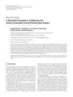
Fig. 3.19: Optical spectra of the proposed WDM optical interface while modelled by VPI
simulator using three WI-DWDM channels: (a): the input signal at port IN, (b): the downlink
signal at port DL Drop, (c): the recovered optical carrier at
λ-Re-Use port, and (d): the uplink
optical mm-wave signal to be added to the interface, generated by reusing the recovered optical
carrier.
105
Chapter 3: WDM Optical Interface for Simplified Antenna Base Stations
the functionality of the proposed interface, which was later demonstrated in
experiment, as described in Section 3.5.3
-5-8
-7
-6
-4
-5
-3
-11
-9
-7
l
o
g
l
o
g
1
0
1
0
(
(
B
E
R
)
)
Received Optical Power (dBm)
Uplink at ADD Port
-5
-3
-11
-9
-7
-9
-8
-7
-6
l
o
g
l
o
g
1
0
1
0
(
(
B
E
R
)
)
Received Optical Power (dBm)
Downlink at DL Drop Port
(a) (b)
-5-8
-7
-6
-4
-5
-3
-11
-9
-7
l
o
g
l
o
g
1
0
1
0
(
(
B
E
R
)
)
Received Optical Power (dBm)
Uplink at ADD Port
-5-8
-7
-6
-4
-5
-3
-11
-9
-7
l
o
g
l
o
g
1
0
1
0
(
(
B
E
R
)
)
Received Optical Power (dBm)
Uplink at ADD Port
-5
-3
-11
-9
-7
-9
-8
-7
-6
l
o
g
l
o
g
1
0
1
0
(
(
B
E
R
)
)
Received Optical Power (dBm)
Downlink at DL Drop Port
-5
-3
-11
-9
-7
-9
-8
-7
-6
l
o
g
l
o
g
1
0
1
0
(
(
B
E
R
)
)
Received Optical Power (dBm)
Downlink at DL Drop Port
(a) (b)
Fig. 3.20: Simulation BER curves that quantify the degradation of the signals due to traversing the
proposed interface: (a): the recovered downlink signal at DL Drop port, and (b): the uplink signal,
generated by reusing the recovered optical carrier, at ADD port.
3.7 Effects of the Performance of O/E Devices
The overall receiver sensitivity of the experimentally demonstrated system
incorporating the proposed interface, irrespective of direction of communication, is
less than or equal to -7.7 dBm at a BER of 10
-9
,
which is very poor and needs to be
improved through further investigation. The performance of the optoelectronic and
electrooptic devices such as DE-MZMs and the PD play a very important role in
limiting the overall performance of the link. The DE-MZMs used in the experiment
exhibit a CSR from 22 to 28 dB. Also, the PD used in the experiment had a
responsitivity of less than 0.4. If the performance of O/E devices can be improved
either by replacing it with better performing devices or by applying some external
106
Chapter 3: WDM Optical Interface for Simplified Antenna Base Stations
performance enhancing techniques (such as CSR reduction by external means), the
sensitivity limitation can be resolved quite easily.
Fig. 3.21 shows a simulation model developed by using VPI platform, which
quantifies the performance enhancement of the system at different values of CSR at
the output of the DE-MZMs and the responsitivity of the PD. To make the results
comparable, the properties of the modules in the model follow the experimental
parameters very closely. To enable variable CSRs in the generated WI-DWDM
signals, the sidebands of the OSSB+C signal are separated from the optical carriers
using a Fabry Perot filter in conjunction with a 3 port optical circulator, where the
intensities of the sidebands were varied by another EDFA (keeping the noise figure
unchanged) before combining them back with the separated optical carriers. Fig.
3.22(a) shows the sensitivity at BER = 10
-9
vs. reduction in CSR curve obtained from
simulation model, which clearly indicates that, the sensitivity of the system increases
almost linearly with reduction in CSR.
1. IN
3. DL Drop
4. λ-Re-Use
5. ADD
7. OUT
10 km
SMF
WDM Optical
Interface
7
3
45
1
Uplink
OSSB+C2
Data Recovery
4
x
1
OSSB+C1
OSSB+C2
OSSB+C3
FP
2
x
1
EDFA
BPF: band pass filter
SMF: single-mode fiber
PD: photo detector
FP: Febry Perot Filter
SB: Sideband
PD
PD
SB
EDFA
BPF
1. IN
3. DL Drop
4. λ-Re-Use
5. ADD
7. OUT
10 km
SMF
WDM Optical
Interface
7
3
45
1
Uplink
OSSB+C2
Data Recovery
4
x
1
OSSB+C1
OSSB+C2
OSSB+C3
FP
2
x
1
EDFA
BPF: band pass filter
SMF: single-mode fiber
PD: photo detector
FP: Febry Perot Filter
SB: Sideband
PD
PD
SB
EDFA
BPF
Fig. 3.21: Simulation model that quantifies the performance enhancement of the system at
different values of the CSR of the DE-MZMs as well as the responsitivity of the photodetector.
107
Chapter 3: WDM Optical Interface for Simplified Antenna Base Stations
To verify the impact of the PD on the overall system performance, the
responsitivity of the PD module in the simulation model were increased gradually
from 20% up to 100% and plotted against the sensitivity of the system at BER = 10
-9
,
which is shown in Fig. 3.22(b). This curve also confirms that the sensitivity of the
system increases almost linearly with responsitivity of the PD and saturates when the
responsitivity > 0.9 A/W. Therefore, both curves (Fig. 3.22a- 3.22b) demonstrate that
with proper selection of the O/E devices, the overall performance of the link can be
enhanced significantly.
-14
-12
-10
-8
-6
-4
Sensitivity (dBm)
0.1 0.3 0.5 0.7 0.9 1.1
PD Responsitivity (A/W)
(b)(a)
-10
-9
-8
-7
-6
-5
-4
Sensitivity (dBm)
-2 0 2 4 6 8 10 12
Reduction in CSR (dB)
S
C
CSR
-14
-12
-10
-8
-6
-4
Sensitivity (dBm)
0.1 0.3 0.5 0.7 0.9 1.1
PD Responsitivity (A/W)
(b)
-14
-12
-10
-8
-6
-4
Sensitivity (dBm)
0.1 0.3 0.5 0.7 0.9 1.1
PD Responsitivity (A/W)
(b)(a)
-10
-9
-8
-7
-6
-5
-4
Sensitivity (dBm)
-2 0 2 4 6 8 10 12
Reduction in CSR (dB)
S
C
CSR
(a)
-10
-9
-8
-7
-6
-5
-4
Sensitivity (dBm)
-2 0 2 4 6 8 10 12
Reduction in CSR (dB)
S
C
CSR
S
C
CSRCSR
Fig. 3.22: Simulation graphs that quantify the performance enhancement of the system at different
values of the CSR of the DE-MZMs as well as the responsitivity of the photodetector: (a):
sensitivity vs. reduction in CSR, and (b): sensitivity vs. PD responsitivity.
108
Chapter 3: WDM Optical Interface for Simplified Antenna Base Stations
3.8 Carrier Reuse over Independent Uplink Light Source
As described in the previous sections, the proposed interface enables a carrier
extraction technique that provides optical carrier to modulate the uplink mm-wave
signals. The downlink optical carrier traverses a series of optical devices, in addition
to propagating through a span of optical fibre before being recovered at the interface.
This transportation of the optical carrier to the interface may potentially cause
broadening of the linewidth of the carrier-pulse due to the Group-Velocity
Dispersion (GVD), which can be expressed mathematically [81] as follows:
()
1
2
2
2
ωβω
ω
β
ω
υω
ω
ω
∆=∆=∆
⎟
⎟
⎠
⎞
⎜
⎜
⎝
⎛
=∆=∆ L
d
d
L
L
d
d
d
dT
T
g
where,
υ
g
, is the group velocity,
β, is the propagation constant
L, is the length of SMF,
∆T, is the amount of pulse broadening,
∆ω, spectral width of the carrier pulse, and
2
2
2
ω
β
β
d
d
=
is the GVD parameter that determines the amount of broadening
In terms of range of wavelengths ∆λ, rather than frequency spread ∆ω, the extent
of pulse broadening ∆T can be expressed as:
()
2
2
21
,
2
β
λ
π
υλ
λλ
υλ
ω
ω
⎟
⎠
⎞
⎜
⎝
⎛
=
⎟
⎟
⎠
⎞
⎜
⎜
⎝
⎛
=
∆=∆
⎟
⎟
⎠
⎞
⎜
⎜
⎝
⎛
=∆=∆
c
d
d
D
where
DL
L
d
d
d
dT
T
g
g
109
Chapter 3: WDM Optical Interface for Simplified Antenna Base Stations
β
2
, is the dispersion parameter expressed in unit of ps/(km-nm)
The above two expressions of pulse broadening demonstrates that there is a
definite broadening of downlink carriers before being recovered in the proposed
interface to be reused for uplink communication. This dispersion induced pulse
broadening contaminates the receiver performance by introducing Intersymbol
Interference (ISI) and by reducing the SNR at the decision circuit.
To quantify the effects of pulse broadening in a system incorporating the proposed
interface, a simulation was carried out using VPITransmissionMaker5.5. The
simulation model was very similar to the experiment, where uplink optical mm-wave
signal was generated in two different ways: (i) by reusing the recovered downlink
carrier, and (ii) by using an independent optical source. In both cases, the BER
curves were measured in the CO. The simulation BER curves are presented in Fig.
3.23. It shows that due to pulse broadening, the uplink signal experiences a 0.1 dB
-3
-5
-7
-9
-11
-8 -7 -6
-5
-4
carrier reuse
independent light-source
loglog
1010
((
BER
)
)
Received Optical Power (dBm)
-3
-5
-7
-9
-11
-3
-5
-7
-9
-11
-8 -7 -6
-5
-4
carrier reuse
independent light-source
loglog
1010
((
BER
)
)
loglog
1010
((
BER
)
)
Received Optical Power (dBm)
Fig. 3.23: Simulated BER curves as a function of received optical power for uplink transmission
while: (i): reused the optical carrier recovered by the proposed interface, and (ii): used an
independent optical source as the uplink optical carrier.
110
Chapter 3: WDM Optical Interface for Simplified Antenna Base Stations
additional penalty, which is very negligible, and can be ignored. Therefore, the effect
of recovered carrier pulse broadening on the overall uplink performance is minimal
and hence can be neglected while designing the mm-wave fibre-radio systems
incorporating the proposed WDM optical interfaces.
3.9 Conclusion
This chapter presented a multifunctional WDM optical interface for future
DWDM fibre-radio system that enables dispersion tolerant OSSB+C modulation
based wavelength-interleaved networks and capable of providing the optical carrier
for the uplink transmission by exploiting a wavelength reuse technique. The
functionality of the proposed interface was verified experimentally as well as via
simulation for three wavelength-interleaved DWDM channels with a channel spacing
of 25 GHz, each carrying 37.5 GHz RF signal with 155 Mb/s BPSK data transported
over 10 km of fibre link. The use of the demonstrated interface in the future DWDM
fibre-radio networks can improve spectral efficiency and ensure efficient wavelength
utilisation, while offers a simplified and consolidated BS architecture by eliminating
the need for separate optical source for uplink. In the design process we have taken
the benefits of matured and standard component technologies that enhance the
possibility of merging the mm-wave fibre-radio based BWA systems with existing
optical network infrastructure in the access and metro domains.
The effects of the performance of optoelectronic devices (DE-MZM and PD) in
the overall performance of the link incorporating the proposed interface were
investigated. A simulation model was developed to investigate the impairments
contributed by imperfect optical devices such as the DE-MZM and PD. The CSR of
the DE-MZM and the responsitivity of the PD were varied and the respective
sensitivities were measured. The results indicated that the performance of the links
incorporating the proposed interface were largely dependent on the performance of
the optoelectronic devices, and by proper selection of these devices, the performance
of the link can be significantly enhanced.
111
Chapter 3: WDM Optical Interface for Simplified Antenna Base Stations
A comparison was carried out to investigate the effects of pulse-broadening due to
dispersion on the optical carriers recovered using wavelength reuse scheme and
independent light-sources in the uplink path. The mathematical expressions showed
that there was a definite broadening of the optical carrier recovered by the proposed
interface to be reused in the uplink path. However, the simulation results
demonstrated that the effects have minimal impact on the overall system
performance and can be ignored while designing the mm-wave fibre radio systems
incorporating the proposed WDM optical interface.
112
Chapter 3: WDM Optical Interface for Simplified Antenna Base Stations
3.10 References
[1] A. J. Cooper, “Fiber/radio for the provision of cordless/mobile telephony services in the
access network,” Electron. Lett., vol. 26, pp. 2054-2056, 1990.
[2] H. Ogawa, D. Polifko, and S. Banba, “Millimeter wave fiber optics systems for personal
radio communication,” IEEE Trans. Microwave Theory Tech., vol. 40, pp. 2285-2293, 1992.
[3] J. O’Reilly and P. Lane, “Remote delivery of video services using mm-waves and optics,” J.
Lightwave Technol., vol. 12, no. 2, pp. 369-375, 1994.
[4] M. Shibutani, T. Kanai, W. Domom, W. Emura, and J. Namiki, “Optical fiber feeder for
microcellular mobile communication system (H-O15),” IEEE Journal on Selected Areas in
Communications, vol. 11, pp. 1118-1126, 1993.
[5] W. I. Way, “Optical fibre-based microcellular systems: an overview,” IEICE Trans.
Commun., vol. E 76-B, no. 9, pp. 1078-1090, 1993.
[6] O. K. Tonguz and J. Hanwook, “Personal communications access networks using subcarrier
multiplxed optical links,” J. Lightwave Technol., vol. 14, pp. 1400-1409, 1996.
[7] P. Mahonen, T. Saarinen, Z. Shelby, and L. Munoz, “Wireless Internet over LMDS:
architecture and experimental implementation,” IEEE Communications Magazine, vol. 39,
pp. 126-132, 2001.
[8] S. Ohmori, Y. Yamao, and N. Nakajima,
“The future generations of mobile communications
based on broadband access technologies,”
IEEE Communications Magazine vol. 38, no. 12,
pp. 134-142, 2000.
[9] J. Zander, “Radio resource management in future wireless networks: requirement and
limitations,” IEEE Communications Magazine, vol. 35, no. 8, pp. 30-36, 1997.
[10] T. Ihara, and K. Fujumura, “Research and development trends of millimetre-wave short-
range application systems,” IEICE Trans. Commun., vol. E 79-B, no. 12, pp. 1741-1753,
1996.
[11] D. Wake, D. Johansson, and D. G. Moodie, “Passive pico-cell—New in wireless network
infrastructure,” Electron. Lett., vol. 33, pp. 404-406, 1997.
[12] D. Novak, G. H. Smith, C. Lim, A. Nirmalathas, H. F. Liu, and R. Waterhouse, “Optically
fed millimeter-wave wireless communications," Proc. Conference on Optical Fiber
Communication (OFC'98), Washington DC, USA, vol. 2, pp. 14, 1998.
[13] C. Lim, A. Nirmalathas, D. Novak, R. S. Tucker, and R. Waterhouse, “Wavelength-
Interleaving Technique to Improve Optical Spectral efficiency In MM-wave WDM Fiber
radio” Lasers and Electro-Optics Society (LEOS ‘01), The 14th Annual Meeting of the IEEE,
San Diego, CA, USA vol. 1, pp. 54 –55, 2001.
113
Chapter 3: WDM Optical Interface for Simplified Antenna Base Stations
[14] C. Lim, A. Nirmalathas, D. Novak, R. S. Tucker, and R. Waterhouse, “Technique for
increasing optical spectrum efficiency in millimeter wave WDM fiber-radio,” Electron. Lett.
, vol. 37, pp. 1043 –1045, 2001.
[15] H. Toda, T. Yamashita, K. Kitayama, T. Kuri, “A DWDM MM-Wave Fiber Radio system
by optical frequency interleaving for high spectra efficiency,” IEEE Top. Meet. On
Microwave Photonics (MWP '01), pp. 85-88, 2001.
[16] K. Kitayama, A. Stöhr, T. Kuri, R. Heinzelmann, D. Jäger, and Y. Takahashi, "An Approach
to Single Optical Component Antenna Base Stations for Broad-Band Millimeter-Wave Fiber-
Radio Access Systems," IEEE Transactions on Microwave Theory and Techniques, vol.48,
no.12, pp.1745-1748, 2000.
[17] L. Noel, D.Wake, D. G. Moodie, D. D. Marcenac, L. D.Westbrook, D.Nesset, “Novel
techniques for high-capacity 60-GHz fiber-radio transmission systems, IEEE Trans.
Microwave Theory Tech., vol. 45, no. 8, pp. 1416-1423, 1997.
[18] D. Everitt, “Traffic capacity of cellular mobile communication systems,” Computer Networks
and ISDN Systems, vol. 20, pp. 447-454, 1990.
[19] M. Berg, S. Pettersson, and J. Zander, “ A radio resource management concept for bunched
personal communication systems, “ Royal Institute of Technology,” Stockholm, 1997.
[20] J. park, and K. Y. Lau, “Millimetre-wave (39 GHz) fiber-wireless transmission of broadband
multichannel compressed digital video,” Electron. Lett., vol. 32, pp. 474-476, 1995.
[21] J. J. O'Reilly, “Performance considerations for MM-wave radio-over-fibre systems,” J. of
the Communications Research Laboratory, vol.46, no. 3, pp. 459, 1999.
[22] R. Heidemann, G. Veith, “MM-wave photonics technologies for Gbit/s-wireless-local-loop,
“Proc. Opto-Electronic Conference in Communications (OECC’98), Chiba, Japan, 1998.
[23] U. Gliese, “Coherent fiber-optic links for transmission and signal processing in microwave
and millimeter-wave systems,” Proc. IEEE Top. Meet. on Microwave Photonics (MWP '98),
pp. 211-214, 1998.
[24] D. Novak, G. H. Smith, C. Lim, A. Nirmalathas, H. F. Liu, and R. Waterhouse, “Fiber-fed
millimeter-wave wirless system,” “Proc. Opto-Electronic Conference in Communications
(OECC’98), Chiba, Japan, 1998.
[25] H. Schmuck, R. Heidemann, “Hybrid fiber-radio field experiment at 60 GHz,” Proc. ECOC
1996, Oslo, pp. 4.59-4.66, 1996.
[26] C. R. Lima, D. Wake, P. A. Davies, “Compact optical millimetre-wave source using a dual-
mode semiconductor laser,” Electron. Lett., vol. 31, no.5 pp. 364-366, 1995.
[27] J. J. O'Reilly, P. M. Lane, R. Heidemann, R. Hofstetter, “Optical generation of very narrow
linewidth millimetre wave signals,” Electron. Lett., vol. 28, no. 25 pp. 2309-2311, 1992.
[28] T. Kuri and K. Kitayama, “60GHz band millimetre-wave signal generation and transport
over optical frequency division multiplexing networks,” Electron. Lett., vol. 32, pp. 2158-
2159, 1996.
114
Chapter 3: WDM Optical Interface for Simplified Antenna Base Stations
[29] K. Kitayama, T. Kuri, H. Yokoyama, and M. Okuno, "60 GHz millimeter-wave generation
and transport over OFDM fiber-optic networks," IEEE Top. Meet. on Microwave Photonics
(MWP’96), Kyoto, Japan, TU3-5, 1996
[30] D. Wake, and D. Moodie, “Passive picocell-an unpowered remote transceiver for short range,
high capacity radio systems,” IEE Colloquium on Fibre Optics in Microwave Systems and
Radio Access, London, UK, pp. 14/1-4, 1997.
[31] D. Wake, D. Moodie, F. Henkel., “The electroabsorption modulator as a combined
photodetector /modulator for analogue optical systems”. Workshop on High Performance
Electron Devices for Microwave and Optoelectronic Applications (EDMO ’97), pp. 147 –
150, 1997.
[32] K A. Persson, A. Alping and D. Wake, “WCDMA radio-over-fibre transmission experiment
using electro-absorption transceiver,” Electron. Lett., vol. 41, no. 13, pp. 764-766, 2005
[33] D. Wake, L. Noel, D. G. Moodie, D. D. Marcenac, L. D. Westbrook, D. Nesset, “A 60 GHz
120 Mb/s QPSK fiber-radio transmission experiment incorporating an electro-absorption
modulator transceiver for a full duplex optical data path” IEEE MTT-S Int. Microwave
Symposium Digest, vol. 1, pp. 39-42, 1997.
[34] D. Wake, and D. Moodie, “Passive picocell-prospects for increasing the radio range,” IEEE
Top. Meet. on Microwave Photonics (MWP’98), Essen, Germany, pp. 269-271, 1998.
[35] L. Noel, D. Wake, D. G. Moodie, D. D. Marcenac, L. D. Westbrook, and D. Nesset, “Novel
techniques for high-capacity 60 GHz fiber-radio transmission systems,” IEEE Trans.
Microwave Theory Tech., vol. 45, pp. 1416–1423, 1997.
[36] L. D. Westbrook and D. G. Moodie, “Simultaneous bi-directional analog fiber-optic
transmission using an electroabsorption modulator,” Electron. Lett., vol. 32, no. 19, pp.
1806–1807, 1996.
[37] L. D. Westbrook, L. No¨el, and D. G. Moodie, “Full-duplex, 25 km analogue fiber
transmission at 120 Mbytes/s with simultaneous modulation and detection in an
electroabsorption modulator,” Electron. Lett., vol. 33, no. 8, pp. 694–695, 1997.
[38] Jager, D., A. Stohr, and R. Heinzelmann “Advanced microwave photonic devices for analog
optical links,” IEEE Top. Meet. On Microwave Photonics (MWP '98), Piscataway, NJ, USA
pp. 153-156, 1998.
[39] A. Stohr, R. Heinzelmann, and D. Jager, “Microwave and millimetre-wave fibre optic links:
full-duplex fibre-wireless network architecture employing EA-transceiver,” Proceedings 10th
MICROCOLL, Budapesti Muszaki Egyetem Memoktovabbkepzo Intezet, Budapest, Hungary,
pp.41-46, 1999.
[40] A. Stohr, K. Kitayama, D. Jager, “Full duplex fiber optic RF subcarrier transmission using a
dual- function modulator/photodetector”, IEEE Trans. Microwave Theory Tech., vol. 47, pp.
1338 –1341, 1999.
115
Chapter 3: WDM Optical Interface for Simplified Antenna Base Stations
[41] A. Stohr, R. Heinzelmann, and D. Jager, “Millimetre-wave bandwidth electroabsorption
modulators and transceivers,” IEEE Top. Meet. On Microwave Photonics (MWP '00),
Piscataway, NJ, USA pp. 125-128, 2000.
[42] A. Stoehr, R. Heinzelmann, T. Kuri, K. Kitayama, D. Jager, “Electroabsorption transceiver
(EAT): device concepts and system applications,” Proc. Int. Soc. Opt. Eng. (SPIE), USA,
pp.314-316. 2000.
[43] K. Kitayama, "An approach to single optical component antenna base station for broadband
millimeter-wave fiber-radio access system (Invited)," OIDA Microwave Phtonics Workshop,
Santa Monica, USA, 2000.
[44] K. Kitayama, T. Kuri, R. Heinzelmann, A. Stöhr, D. Jäger, and Y. Takahashi, "A good
prospect for broadband millimeter-wave fiber-radio access system - An approach to single
optical component at antenna base station (Invited)," Proc. Microwave Symposium Digest,
IEEE MTT-S, TH4C-3, vol. 3, pp. 1745-1748, 11-16 June, 2000.
[45] T. Kuri, K. Kitayama, and Y. Takahashi, "60-GHz-band full-duplex radio-on-fiber system
using two-RF-port electroabsorption transceiver," IEEE Photonics Technol. Lett
, vol. 12, no.
4, pp. 419-421, 2000.
[46] K. Kitayama, K. Ikeda, T. Kuri, A. Stohr, and Y. Takahashi, “Full duplex demonstration of
single electro-absorption transceiver base station for mm-wave fiber radio system,” IEEE
Top. Meet. On Microwave Photonics (MWP '01), pp. 73 –76, 2001.
[47] N. Dagli., “Wide-bandwidth lasers and modulators for RF Photonics,” IEEE Trans,
Microwave Theory Tech., vol. 47, pp. 1151-1171, 1999.
[48]
T. Ido, S. Tanaka, M. Suzuki, M. Koizumi, H. Sano, and H. Inoue, “Ultra high-speed multiple
quantum well electro-absorption optical modulators with integrated waveguides,” J.
Lightwave Technol., vol. 14, pp. 2026-2034, 1996.
[49] A. Nirmalathas, C. Lim, D. Novak, R. Waterhouse, “Progress in Millimeter-Wave Fiber-
Radio Access Networks,” Annals of Telecommunications, vol. 56, pp. 27-38, 2001.
[50] U. Gliese, S. Norskov, and T. N. Nielsen, “Chromatic dispersion in fiber-optic microwave
and millimeter-wave links,” IEEE Trans. Microwave Theory Tech., vol. 44, no. 10, pp. 1716-
1624, 1996.
[51] H. Schmuck, “Comparison of optical millimetre-wave system concepts with regard to the
chromatic dispersion,” Electron. Lett., vol. 31, pp. 1848-1849, 1995.
[52] R. A. Griffin, P. M. Lane, and J. J. O’Reilly, “Dispersion-tolerant subcarrier data modulation
of optical millimeter-wave signals,” Electron. Lett., vol. 32, no. 24, pp. 2258-2260, 1996.
[53] G. H. Smith, D. Novak, and Z. Ahmed, "Technique for optical SSB generation to overcome
dispersion penalties in fiber-radio systems," Electron. Lett., vol. 33, pp. 74-75, 1997.
[54] G. H. Smith, D. Novak, and Z. Ahmed, “Overcoming chromatic dispersion effects in fiber-
wireless systems incorporating external modulators,” IEEE Trans. Microwave Theory Tech.,
vol. 45, no. 8, pp. 1410-1415, 1997.
116
Chapter 3: WDM Optical Interface for Simplified Antenna Base Stations
[55] K. Kitayama, T. Kuri, K.Onohara, T.Kamisaka, K.Murashima, "Dispersion effects of FBG
filter and optical SSB filtering in DWDM millimeter-wave fiber-radio systems," J. Lightwave
Technol., vol. 20, pp. 1397-1407, 2002.
[56] T. Kuri, K. Kitayama, A. Stohr, and Y. Ogawa, “Fiber-optic millimeter-wave downlink
system using 60 GHz-band external modulation,” J. Lightwave Technol., vol.17, no. 5, pp.
799-806, 1999.
[57] T. Kuri, K. Kitayama, Y. Takahashi, “A single light-source configuration for full-duplex 60-
GHz-band radio-on-fiber system,” IEEE Trans, Microwave Theory Tech., vol. 51, pp. 431-
439, 2003.
[58] A. Nirmalathas, C. Lim, D. Novak, R. Waterhouse, “Optical interfaces without light sources
for base station designs in fiber-wireless systems incorporating WDM,” IEEE Top. Meet. On
Microwave Photonics (MWP '99), vol.1 pp.119-122, 1999.
[59] A. Nirmalathas, D. Novak, C. Lim, R. Waterhouse, “Wavelength Reuse in the WDM Optical
Interface of a Millimeter-Wave Fiber-Wireless Antenna Base Station,” IEEE Trans.
Microwave Theory Tech., vol. 49, pp. 2006-2012, 2001.
[60] T. Kuri, K. Kitayama, and Y. Takahashi, “Simplified BS without light source and RF local
oscillator in full duplex millimeter-wave radio-on-fiber system based upon external
modulation technique,” IEEE Top. Meet. On Microwave Photonics (MWP '99), Piscataway,
NJ, USA, vol.1 pp.123-126, 1999.
[61] L.T. Nichols, and R. D. Esman, “Single sideband modulation techniques and applications,”
Proc. Conference on Optical Fiber Communication (OFC'99), San Diego, CA, USA, THW1-
1, 1999.
[62] G. H. Smith, D. Novak, and C. Lim, “A millimeter-wave full-duplex WDM/SCM fiber-radio
access network,” Proc. Conference on Optical Fiber Communication (OFC'98), Washington
DC, USA, vol. 2, pp. 18-19, 1998.
[63] R. A. Griffin, P. M. Lane, and J. J. O’Reilly, “Radio-over-fiber distribution using an optical
millimeter-wave/DWDM overlay,” Proc. Conference on Optical Fiber Communication and
the International Conference on Integrated Optics and Optical Fiber Communications
(OFC/IOOC'99),San Diego, CA, USA, vol. 2, pp. 70-72, 1999
[64] K. Kojucharow, M. Sauer, H. Kaluzni, D. Sommer, and C. G. Schaffer,
“Experimental
investigation of WDM channel spacing in simultaneous upconversion millimeter-wave fiber
transmission system at 60 GHz-band,”
IEEE MTT-S Int. Microwave Symposium Digest,
vol.2, pp. 1011-1012, 2000.
[65] M. A. Al-mumin and G. Li, “WDM/SCM optical backbone for 60 GHz wireless systems,”
Proc. IEEE. Top. Meet. on Microwave Photonics (MWP2001), Long Beach, CA, USA, pp.
61-64, 2001.
117
Chapter 3: WDM Optical Interface for Simplified Antenna Base Stations
[66] C. Marra, A. Nirmalathas, C. Lim, D. Novak, B. Ashton, L. Poladian, W. S. T. Rowe, T.
Wang, and J. A. Besley, “Wavelength-interleaved OADMs incorporating optimized multiple
phase-shifted FBGs for fiber-radio systems,” J. Lightwave Technol., vol. 21, pp. 32-39, 2003.
[67] C. Marra et. al., “OADM with a multiple phase-shifted FBG for a wavelength-interleaved
millimeter-wave fiber-radio system,” Optical Fiber Communication Conference (OFC’02),
pp. 413-415, 2002.
[68] H. Toda, T. Yamashita, K. Kitayama, T. Kuri, “Demultiplexing using an arrayed-waveguide
grating for frequency-interleaved DWDM radio-on-fiber systems with 25-GHz channel
spacing,” Proc. Int. Soc. Opt. Eng. (SPIE), vol. 4906, USA, pp. 99-106, 2002
[69] H. Toda, T. Yamashita, T. Kuri, K. I. Kitayama,, “Demultiplexing using an arrayed-
waveguide grating for frequency-interleaved DWDM millimeter-wave radio-on-fiber
systems,” J. Lightwave Technol., vol. 21, pp. 1735-1741, 2003.
[70] M. Bakaul, A. Nirmalathas, and C. Lim, “Dispersion Tolerant Novel Base Station Optical
Interface for Future WDM Fiber-Radio Systems,” Proc. of Conference on Optical Internet/
Australian Conference on Optical Fiber Technology (COIN/ACOFT’03), pp. 683-686, 2003.
[71] M. Bakaul, A. Nirmalathas, and C. Lim, “Multifunctional WDM optical interface for
millimeter-wave fiber-radio antenna base station,” Journal of Lightwave Technol., vol. 23,
no. 3, pp. 1210-1218, 2005.
[72] A. Nirmalathas, C. Lim, M. Attygalle, D. Novak, R. Waterhouse, and M. Bakaul, "Recent
progress in fiber-wireless networks: Technologies and architectures" Proc. ICOCN2003,
Bangalore, India, Oct. 2003 (invited).
[73] M. Bakaul, A. Nirmalathas, and C. Lim, “Experimental verification of cascadability of WDM
optical interfaces for DWDM Millimeter-wave fiber-radio base station,” IEEE Top. Meet. On
Microwave Photonics (MWP '04), pp. 169 –172, 2004.
[74] A. Loayssa, C. Lim, A. Nirmalathas, and D. Benito,
“Optical single-sideband modulator for
broad-band subcarrier multiplexing systems,"
IEEE Photon. Technol. Lett. (PTL), vol. 15, no.
2, pp. 311-313, 2003.
[75]
A. Loayssa, D. Benito, and M. J. Garde, “Single-sideband suppressed-carrier modulation
using a single-electrode electrooptic modulator,”
IEEE Photon. Technol. Lett. (PTL), vol. 13,
no. 8, pp. 869-871, 2001.
[76] A. Loayssa, C. Lim, A. Nirmalathas, and D. Benito,
“Design and performance of the
bidirectional optical single-sideband modulator,” J.
Lightwave Technol., vol. 21, no. 4, pp.
1071-1082, 2003.
[77] R. D. Esman and K. J. Williams, “Wideband efficiency improvement of fiber optic systems
by carrier subtraction,” IEEE Photon. Technol. Lett., vol. 7, no. 2, pp. 218-220, Feb. 1995.
[78] K. J. Williams and R. D. Esman, “Stimulated Brillouin scattering for improvement of
microwave fiber-optic link efficiency,” Electron. Lett., vol. 30, pp. 1965-1966, 1994.
118
Chapter 3: WDM Optical Interface for Simplified Antenna Base Stations
[79] M. R. Phillips, D. M. Ott, “Crosstalk due to optical fiber nonlinearities in WDM CATV
lightwave systems,” J. Lightwave Technol., Vol.17, pp.1782-1791, 1999.
[80] L. Cheng, S. Aditya, Z. Li, A. Alphones and M. Ong, “Nonlinear distortion due to XPM in
dispersive WDM microwave fiber-optic links with optical SSB modulation,” International
Topical Meeting on Microwave Photonics, MWP, 2005.
[81] G. P. Agrawal, Fiber-Optic Communication Systems, 3rd ed. (Wiley, New York, 2002);
Greek Translation, 2000.
119
Chapter 3: WDM Optical Interface for Simplified Antenna Base Stations
120
Chapter 4: Characterisation and Enhancement of Links Performance
Incorporating WDM Optical Interface
Characterisation and Enhancement
of Links Performance Incorporating
WDM Optical Interface
4
4.1 Introduction
Chapter 3 presented a multifunctional wavelength-division-multiplexed (WDM)
optical interface with the capacity to add and drop optical millimetre-wave (mm-
wave) signals to and from the wavelength-interleaved dense-wavelength-division-
multiplexed (WI-DWDM) fibre-radio networks with a DWDM channel separation of
25 GHz, which also enables wavelength reuse in the uplink direction by eliminating
the need for a light-source at the base station (BS) [1-3]. The use of such interface in
future DWDM fibre-radio networks will offer higher spectral efficiency, efficient
wavelength utilisation and transparent wavelength routing, while realising simple,
compact and low-cost BSs [2]. The interface, which is comprised of narrow band
fibre Bragg gratings (FBGs) and multiport optical circulator (OC), exploits the
121
Chapter 4: Characterisation and Enhancement of Links Performance
Incorporating WDM Optical Interface
benefits of matured WDM component technologies that enhance the possibility of
merging the mm-wave fibre-radio based broadband wireless access (BWA) systems
with existing optical network infrastructure in the access and metro domains [4-8].
However, the constituent elements of the interface have the potential to degrade the
performance of systems by introducing additional network impairments, such as,
optical crosstalk and chromatic dispersion [9-14]. Moreover, the concatenation of the
interfaces in a practical network will make the effective passband narrower due to the
variations in the passband roll-off and ripple in each individual FBG transfer
functions [15-17]. The required accuracy in these systems therefore, becomes more
stringent with the number of stages in cascade [18-19].
As discussed in Chapter 3, the overall performance of a mm-wave fibre-radio
system is largely dependent on the achieved modulation depths with the wideband
electrooptic intensity modulators, such as dual-electrode Mach-Zehnder modulators
(DE-MZMs). In the case of the optical single sideband with carrier (OSSB+C)
modulated optical mm-wave signal [20-22] transmission, carrier-to-sideband ratio
(CSR), which is inversely proportional to the modulation depth, were found to be
better measure of predicting the performance. A simulation was carried in section 3.7
where the modulation sidebands, which were separated from the respective optical
carriers using a Fabry-Perot (FP) filter and a 3-port OC, were amplified by an erbium
doped fibre amplifier (EDFA) before recombining them using a 3-dB coupler. The
demonstrated results confirm the effectiveness of the reduction of CSRs by the
external means in increasing the performance of analogue fibre optic links. Similar to
the others [20, 22], this external technique however, adds up in cost and complexity
of the systems, and may turn the systems impracticable. Instead, if the proposed
WDM optical interface, in addition to its routine functionality, can be enabled to
reduce the CSRs by avoiding additional hardware, efficient and effective fibre-radio
network architecture can be easily realised.
This chapter thus focuses on the characterisation as well as the enhancement of
the performance of the fibre-radio links incorporating the proposed WDM optical
interface. Both simulations as well as experimental approaches have been taken in
order to achieve this. Section 4.2 gives a brief description about the possible
impairments in a fibre-radio link incorporating the proposed WDM optical interface.
122
Chapter 4: Characterisation and Enhancement of Links Performance
Incorporating WDM Optical Interface
Section 4.3 presents a simulation that study and characterise the effects of optical
impairments on the optical mm-wave signals, while traversing through single as well
as cascaded interfaces. Experimental investigations of the performance of single and
cascaded interfaces are demonstrated in Section 4.4. MM-wave fibre-radio links
(incorporating WDM optical interface) in star-tree and ring/bus network architectures
are modelled in Section 4.5, from which number of allowable interfaces in cascade
can be predicted. Section 4.6 incorporates modification in the proposed WDM
optical interface that enables significant improvement in link’s performance, both in
uplink and downlink direction. The improvements in performances are quantified by
another experiment presented in Section 4.7. The impact of the incorporation of
modification on the overall network performance is quantified in Section 4.8.
4.2 Optical Impairments Introduced by the WDM
Optical Interface
Practical WDM networks (e.g. ring/bus networks) are promising technologies to
achieve high capacity transparent optical networks that offer advanced routing
functionality through optical add-drop-multiplexers (OADMs) [23-26]. DWDM
compatible wavelength interleaving (WI) technique has been introduced in mm-wave
fibre-radio networks [27-29], where a large number of BSs, required to cover a
certain geographical area, are supported via a single central office (CO). In these
networks the downlink optical mm-wave signals with an effective DWDM channel
separation are passed through a suitable multiplexer in CO and are aggregated before
being launched on to the fibre network. The multiplexed signals are then launched on
to the fibre network and transported to the BSs, where each of the BS recovers the
desired downlink signal by using a suitable OADM. The uplink optical mm-wave
signals generated in the BSs are also added to the network via the same OADM and
being transported to the CO. Therefore, in WI-DWDM fibre-radio networks, the
optical mm-wave signals encounter wavelength-selective OADMs on the way to its
123
Chapter 4: Characterisation and Enhancement of Links Performance
Incorporating WDM Optical Interface
destination, which have the potential to cause performance degradation through both
in-band and out-of-band optical crosstalk [11-14, 30, 31].
Another potential source of performance degradation via an OADM is the
dispersion penalty introduced by the FBGs [9, 10, 32, 33], which are widely used as
narrow-band notch filters in the OADMs in recovering the desired signals.
Moreover, the various architectures of the optical networks (e.g. ring/bus) result in
concatenated OADMs, which makes the effective passband of the cascade narrower
due to the passband curvature and ripple of the FBG transfer functions. The required
wavelength stability and accuracy in networks therefore goes up with the number of
cascaded stages. The accumulated effects of all the above will give rise to signal
waveform distortion leading to significant network performance degradation [15-17].
Similar to a conventional OADM, WDM optical interface (shown again in Fig.
4.1 for convenience) is also comprised of multiple FBGs and multiport OC and has
the capacity of adding and dropping optical mm-wave signals to and from the WI-
DWDM fibre-radio networks, in addition to enabling wavelength reuse in the uplink
ADD
DL
Drop
OUT
IN
λ-Re
-Use
5
1
4
3
2
6
7
FBG1
FBG2
ADD
DL
Drop
OUT
IN
λ-Re
-Use
5
1
4
3
2
6
7
FBG1
FBG2
Fig. 4.1: WDM optical interface, to be characterised in single as well as cascaded configuration,
enables wavelength recovery and optical add-drop functionality for a WI-DWDM fibre-radio
system.
124
Chapter 4: Characterisation and Enhancement of Links Performance
Incorporating WDM Optical Interface
direction. Therefore, the optical mm-wave signals in a WI-DWDM network
incorporating the WDM optical interface will be contaminated by the optical
crosstalk as well as the grating dispersion, which will be accumulated for cascaded
setup [2, 34, 35]. Moreover, the interface itself contains a double-notch FBG for
which the wavelength stability and accuracy becomes more stringent than a
conventional OADM. The following section develops a simulation model by which
the effects of such impairments on the optical mm-wave signals are characterised
while traversing single as well as cascaded interfaces.
4.3 Simulation Characterisation of the Performance of
Single and Cascaded WDM Optical Interfaces
4.3.1 Simulation Model
The simulation model that study and characterise the effects of optical
impairments introduced by single as well as cascaded WDM optical interfaces was
developed by using VPITransmissionMaker, a commercially available platform for
photonic simulations. The schematic diagram of the model is shown in Fig. 4.2. In
the downlink direction, three OSSB+C generators are combined and interleaved by
using a 4x1 combiner, amplified by an EDFA and followed by an optical band pass
filter (BPF) to minimise the out-of-band asynchronous spontaneous emission (ASE).
The filtered output was then transported over 10 km of singlemode fibre (SMF) to
the two concatenated WDM optical interfaces, WDM Optical Interface1 and WDM
Optical Interface 2. Each interface is shown as a block with five ports, namely, the
input (IN), downlink drop (DL Drop), wavelength reuse drop (λ-Re-Use), add
(ADD) and output (OUT).The OSSB+C generators consist of three narrow linewidth
optical carriers spaced at 25 GHz, where each of the carrier is modulated by a 37.5
GHz mm-wave signal carrying 155 Mb/s binary-phase-shift-keyed (BPSK) data. The
optical spectrum of the wavelength-interleaved signals entering the interfaces can be
seen in the inset of Fig. 4.2, where for simplicity, the three interleaved downlink
125
Chapter 4: Characterisation and Enhancement of Links Performance
Incorporating WDM Optical Interface
signals with their modulation sidebands are denoted as Ch
1
, Ch
2
and Ch
3
. The
simulation model assigns WDM Optical Interface1 and WDM Optical Interface2 to
drop and add Ch
2
and Ch
1
respectively.
In the uplink (UL) direction, the OSSB+C formatted UL Ch
2
and Ch
1
were
generated by modulating the recovered λ-Re-Use carriers of the interfaces with 37.5
GHz-band UL mm-wave signals, each carrying 155 Mb/s BPSK data. The uplink
signals were then routed to interfaces via the ADD ports. The effects of impairments
on the WI-DWDM signals due to traversing the concatenated interfaces were
characterised by recovering the transmitted signals at positions A, B, C, D, E, and F
as indicated in Fig. 4.2. The simulation model incorporated the observed parameters
of the experiment demonstrated in Section 3.5 of Chapter 3 such that the simulation
study closely follows the experimental setup as far as possible. A tunable double-
notch FBG module alongwith a 3–port OC module were used to recover the desired
signals at points A, D and F. The bit error rate (BER) curves for different channels at
1. IN
3. DL Drop
4. λ-Re-Use
5. ADD
7. OUT
A
B
C
E
D
F
OADM1
7
3
4
5
1
PD & Data Recovery
Uplink
OSSB2+C2
OADM2
7
3
4
5
1
PD & Data Recovery
Uplink
OSSB1+C1
10 km
SMF
4
x
1
OSSB1+C1
OSSB2+C2
OSSB3+C3
EDFA
BPF
Frequency (THz)
-50
0
193.125
193.20
193.05
Ch
1
Ch
2
Ch
3
Optical Intensity (dBm)
1. IN
3. DL Drop
4. λ-Re-Use
5. ADD
7. OUT
A
B
C
E
D
F
OADM1
7
3
4
5
1
OADM1
7
3
4
5
1
PD & Data Recovery
Uplink
OSSB2+C2
OADM2
7
3
4
5
1
OADM2
7
3
4
5
1
PD & Data Recovery
Uplink
OSSB1+C1
10 km
SMF
4
x
1
OSSB1+C1
OSSB2+C2
OSSB3+C3
EDFA
BPF
Frequency (THz)
-50
0
193.125
193.20
193.05
Ch
1
Ch
2
Ch
3
Optical Intensity (dBm)
Frequency (THz)
-50
0
193.125
193.20
193.05
Ch
1
Ch
2
Ch
3
Optical Intensity (dBm)
Fig. 4.2: Simulation setup to characterise the effects of optical impairments in single and cascaded
WDM optical interfaces in a WI-DWDM fibre-radio system.
126
Chapter 4: Characterisation and Enhancement of Links Performance
Incorporating WDM Optical Interface
different positions were obtained by changing the Centre frequencies of the FBGs
while keeping all other properties and parameters unchanged.
4.3.2 Simulation Results and Discussion
Fig. 4.3 shows the BER curves for downlink Ch
2
at point A with other two
channels (Ch
1
and Ch
3
) ON and OFF, respectively. Recovered downlink Ch
2
at point
A experiences a negligible 0.15 dB power penalty that can be attributed to the effects
of out-of-band crosstalk caused by the neighboring Ch
1
and Ch
3
.
Wavelength-interleaved downlink signals (Ch
1
, Ch
2
, and Ch
3
), immediately after
entering to the WDM Optical Interface1, encounters the FBG1 at port 2 of the
multiport OC. This results in a fraction of neighboring interleaved signals (Ch
1
and
Ch
3
) to be reflected and passed through the DL Drop port of the interface alongwith
the desired downlink Ch
2
that contaminates the recovered downlink signal at DL
Drop port of the interface by out-of-band crosstalk. Also, the UL Ch
2
added to the
-4
-5
-6
-7
-8
-9
-10
-11
-9 -8.5 -8 -7.5 -7 -6.5 -6
Ch
1
and Ch
3
ON
Ch
1
and Ch
3
OFF
Ch
2
at A with:
l
o
g
1
0
(
B
E
R
)
Received Optical Power (dBm)
-4
-5
-6
-7
-8
-9
-10
-11
-9 -8.5 -8 -7.5 -7 -6.5 -6
Ch
1
and Ch
3
ON
Ch
1
and Ch
3
OFF
Ch
2
at A with:
l
o
g
1
0
(
B
E
R
)
Received Optical Power (dBm)
Fig. 4.3: Simulation BER curves as a function of received optical power at point A showing
downlink Ch
2
with Ch
1
and Ch
3
ON and OFF respectively.
127
Chapter 4: Characterisation and Enhancement of Links Performance
Incorporating WDM Optical Interface
interface encounters FBG1 while traversing from the ADD port to the OUT port that
allows a fraction of the UL Ch
2
to be transmitted to the DL Drop port, causing in-
band crosstalk to affect the desired downlink Ch
2
. The interface therefore, causes
both out-of-band and in-band crosstalk, in addition to the effects of grating
dispersion as well as the concatenated FBG-notches that contaminate the desired
downlink signals while recovered via DL Drop port. To quantify the effects of these
impairments, a set of BER curves for downlink Ch
2
were measured at point B ( the
DL Drop port of WDM Optical Interface1) under three different conditions: (i)
removing Ch
1
and Ch
3
from the downlink interleaved channels along with the uplink
Ch
2
from the ADD port, (ii) removing only the uplink Ch
2
from the ADD port, but
Ch
1
and Ch
3
are present, and, (iii) all the three interleaved channels along with the
added uplink Ch
2
are present. The measured BER curves are shown in Fig. 4.4.
Similar to the BER curves at point A, it again shows that the downlink Ch
2
experiences a negligible ~0.15 dB power penalty due to the presence of out-of-band
-4
-3
-5
-6
-7
-8
-9
-10
-11
-12
-10 -9.5 -9 -8.5 -8 -7.5 -7 -6.5 -6
Ch
1
and Ch
3
ON, No ADD
Ch
1
and Ch
3
ON, ADDED UL
Ch
1
and Ch
3
OFF, No ADD
Ch
2
at B with:
l
o
g
1
0
(
B
E
R
)
Received Optical Power (dBm)
-4
-3
-5
-6
-7
-8
-9
-10
-11
-12
-10 -9.5 -9 -8.5 -8 -7.5 -7 -6.5 -6
Ch
1
and Ch
3
ON, No ADD
Ch
1
and Ch
3
ON, ADDED UL
Ch
1
and Ch
3
OFF, No ADD
Ch
2
at B with:
l
o
g
1
0
(
B
E
R
)
Received Optical Power (dBm)
Fig. 4.4: Simulation BER curves as a function of received optical power at point B for downlink
Ch
2
with: (i) none of the downlink Ch
1
, Ch
3
or uplink Ch
2
present, (ii) downlink Ch
1
and Ch
3
present, but no uplink Ch
2,
and (iii) all the downlink as well as uplink channels present.
128
Chapter 4: Characterisation and Enhancement of Links Performance
Incorporating WDM Optical Interface
crosstalk from the neighboring Ch
1
and Ch
3
, which however, increases to ~0.30 dB
when the uplink signal is added to the interface contaminating the downlink Ch
2
by
in-band crosstalk.
To see the overall effects of encountering WDM Optical Interface1, BER curves
for downlink Ch
2
measured at point B (having Ch
1
, Ch
3
and uplink Ch
2
present) and
A (having Ch
1
and Ch
3
present) are compared in Fig. 4.5. It shows that, instead of
exhibiting additional power penalty, downlink Ch
2
at B demonstrates an
improvement of power penalty (negative power penalty) by approximately 0.3 dB.
This can be attributed to the suppression of optical carrier of DL Ch
2
by as much as
50% (as a result of wavelength reuse for the uplink path via FBG2) that in turn
increases the CSR of the downlink Ch
2
by 3-dB before being recovered via DL Drop
port.
-4
-5
-6
-7
-8
-9
-10
-11
-9.5 -9 -8.5 -8 -7.5 -7 -6.5 -6 -5.5
Ch
2
at A
Ch
2
at B
With three channels ON:
l
o
g
1
0
(
B
E
R
)
Received Optical Power (dBm)
-4
-5
-6
-7
-8
-9
-10
-11
-4
-5
-6
-7
-8
-9
-10
-11
-9.5 -9 -8.5 -8 -7.5 -7 -6.5 -6 -5.5-9.5 -9 -8.5 -8 -7.5 -7 -6.5 -6 -5.5
Ch
2
at A
Ch
2
at B
With three channels ON:
l
o
g
1
0
(
B
E
R
)
Received Optical Power (dBm)
Fig. 4.5: Comparison of the BER curves for downlink Ch
2
measured at points B (with downlink
Ch
1
and Ch
3
, as well as uplink Ch
2
present) and A (with all the three downlink channels present).
129