Expert Systems for Human Materials and Automation Part 5 pot
Bạn đang xem bản rút gọn của tài liệu. Xem và tải ngay bản đầy đủ của tài liệu tại đây (4.06 MB, 30 trang )
Advances in Health Monitoring and Management
111
2.1.2 Engineering system
An engineering system is a system that is technologically enabled, has significant socio-
technical interactions and has substantial complexity. Moses [7] presents some types and
foundational issues with engineering systems. Engineering systems are interdisciplinary in
nature and are devoted to addressing large-scale, complex engineering challenges within
their socio-political context. These can further be defined as systems with diverse, complex,
physical designs that may include components from several engineering disciplines, as well
as economics, public policy, and other sciences. Some of the easiest systems to understand
are mechanical systems. Simple systems are often constructed for a single purpose and
generally have few parts or subsystems. For instance the cooling system in a car may consist
of a radiator, a fan, a water pump, a thermostat, a cooling jacket, and several hoses and
clamps. Together they function to keep the engine from overheating, but separately they are
useless. Similar to biological systems, all system components must be present and they must
be arranged in the proper way. Removing, misplacing or damaging one component puts the
whole system out of commission.
2.1.3 Biological-engineering system
Biological-engineering systems also referred to as bioengineering systems, consist of
interrelated and interdependent biological and engineering systems or objects. From the
medical perspective, bioengineering integrates physical, chemical, or mathematical sciences
and engineering principles for the study of biology, medicine, behavior, or health. It
advances fundamental concepts, creates knowledge from the molecular to the organ
systems levels, and develops innovative biologics, materials, processes, implants, and
devices for the prevention, diagnosis, and treatment of disease, for patient rehabilitation,
and for improving health. It is clear that bioengineering is concerned with applying an
engineering approach (systematic, quantitative, and integrative) and an engineering focus
(the solutions of problems) to biological problems, it is also concerned with applying
biological knowledge and processes to engineering problems. From an engineering
perspective, bioengineering systems are those that are built specifically to work in
conjunction with the human body, often to amplify its capability and improve its
performance. One of the most basic examples is the operation of a baseball bat or similar
tools. The mechanical subsystem does nothing until it is combined with the human
component of the system. While the biological component can do a whole lot without the
tool, it would be hard pressed for the tool to perform its intended function. Cardiac
pacemakers provide another, more complex, bioengineering example of the interrelated and
interdependent biological and engineering systems.
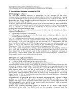
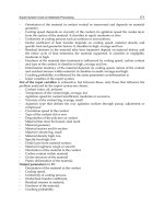
Figure 1, represents a simplified perspective of a selected biological system [8-9]. Figure 2
[10] illustrates the human levels of organization from cellular to tissue, organ and organ
system (human body). Within each cell is a biological and metabolic system that creates and
uses energy that is necessary for the cell’s life and function. There are many types of cells in
the body, such as bone cells, muscle cells (myocytes), liver cells (hepatocytes), heart cells
(cardiocytes), nerve cells, skin cells, and kidney cells. The latter are a large collection
permitting the development of tissues hence the development of muscle tissues, connective,
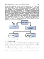
epithelial, and nervous tissues. Figure 3 [11-12] represent engineering and bioengineering
systems, respectively.
Expert Systems for Human, Materials and Automation
112
Fig. 1. Perspective and simplified model of a biological system.
Advances in Health Monitoring and Management
113
(a)
(b)
Fig. 2. Example of human cells, tissues, organs, and organ systems.
Expert Systems for Human, Materials and Automation
114
(a)
(b)
Fig. 3. Systems – (a) Engineering system (gas turbine engine) (b) Biological-Engineering
system (artificial leg).
Advances in Health Monitoring and Management
115
2.2 Health monitoring, diagnostics and prognostics (HMDP)
2.2.1 Health monitoring (HM)
A health monitoring system is a framework that enables the monitoring and reporting on
the state or events of a particular system. Events are detected through a network of sensors.
Detected events are logged or registered within the system in an event logger. These events
could either be evaluated in the event logger or transmitted for evaluation. Outcome of the
evaluation is transmitted through a notification process to systems with decision making
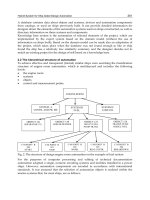
capability for action and intervention. Figure 4 illustrates a framework for remote patient
and structural health monitoring. This framework goes beyond the monitoring and
reporting function and presents the full cycle of health monitoring and prevention process
for any system including biological, engineering or bio-engineering systems. Health
monitoring is further defined as an approach to evaluating errors in or collecting general
information about a system. In general, the approach presented in Figure 4 uses event
classification that identifies events to a provider in order to intervene with appropriate
actions.
Fig. 4. A framework for remote patient and structural health monitoring.
2.2.2 Health diagnostics (HD)
Diagnostics is the branch of medical science that deals with diagnosis [13]. Diagnosis can be
defined as the nature of a disease [14]; the identification of an illness or a conclusion or
decision reached by diagnosis. To the Greeks, a diagnosis meant specifically a
"discrimination, a distinguishing, or a discerning between two possibilities." Today, in
medicine, that corresponds more closely to a differential diagnosis. The latter is defined as
the process of weighing the probability of one disease versus that of other diseases possibly
accounting for a patient's illnesses. In structural engineering, diagnostics can be defined as
the nature of a structural damage (e.g. impact, corrosion, fatigue); the identification of the
degree of damage or a conclusion or decision reached by the diagnosis for future action.
Figure 5, illustrates a diagnosis system framework applicable to all systems including
biological, engineering or bio-engineering systems.
Fig. 5. A framework of a diagnostic system.
Expert Systems for Human, Materials and Automation
116
2.2.3 Health prognostics (HP)
The word prognostic is taken from the Greek Prognostikos (of knowledge beforehand). It
combines pro (before) and gnosis (a knowing). The word is used today to mean a foretelling of
the course of a disease [14]. Prognostic is also defined as relating to prediction [15]. It is also
referred to as a sign of a future happening or a sign or symptom indicating the future course of
an event. In medicine as well as in engineering, it refers to any symptom or sign used in
making a prognosis. Figure 6 [16] illustrates the relationship between the health monitoring,
health diagnostics and prognostics, where the outcome (Remaining Useful Life (RUL)) of the
prognostics module is based on the exploitation of modeling tools and sensor data.
Fig. 6. A framework of a prognostics system.
At this juncture it is important to observe that the referred to terminology employed human
systems and medical references as illustration platforms. It is well known that biological
systems are the most complex, intelligent, expert and adaptive systems that science has
encountered. It is without doubt that the evolution of our engineering systems has exploited
these systems to enable the development of our current technologically-oriented, modern
society. Lessons learned from bird’s flight patterns and techniques have enabled more
efficient, reliable and safe air travel. Understanding the evolution of sea life has provided
key framework and concepts in the design of unobservable, high depth, high efficiency, self-
powered and autonomous submarines.
For bio-inspired engineering systems the terminology is to some extent altered to reflect
specific systems, applications, domains, and fields; however, in recent years, several
perspectives and terminology have emerged, in the engineering discipline, particularly in
the field of Structural Health Monitoring (SHM) and Prognostics Heath Management (PHM)
communities. The following provides the evolution on the usage of the introduced
terminology.
Advances in Health Monitoring and Management
117
2.3 Diagnostics, prognostics health management (DPHM or PHM)
In recent years, the discipline of Diagnostics, Prognostics and Health Management (DPHM)
has been formalized to address the information management and prediction requirements
of operators of complex systems (e.g. aircraft, power plants, and networks) including their
need for on-line health monitoring. Generally, PHM systems incorporate functions of
condition monitoring, state assessment, fault or failure diagnostics, failure progression
analysis, predictive diagnostics (i.e., prognostics), and maintenance or operational decision
support. Ultimately, the purpose of any DPHM or PHM system is to maximize the
operational efficiency, availability and safety of the target system.
As defined by Industry Canada (IC) [17], diagnostics refers to the process of determining the
state of a component to perform its function(s) based on observed parameters; prognostics
refers to predictive diagnostics which includes determining the remaining life or time span
of proper operation of a component; and health management is the capability to make
appropriate decisions about maintenance actions based on diagnostics/prognostics
information, available resources, and operational demand. Figures 7 [18] provides a
framework for health assessment and prognostics of electronic products as an alternative to
traditional reliability prediction methods.
Fig. 7. A framework for health assessment and prognostics of electronic products.
2.4 Structural health monitoring (SHM)
SHM stands principally for structural health monitoring. It also stands for structural health
management, systems health monitoring and systems health management. It must not be
confused with Vehicle Health Monitoring or Management (VHM) which includes propulsion
and avionics systems. Moreover, Structural Damage Sensing (SDS) is also referred to as SHM.
Structural Health Monitoring (SHM) capability is a life cycle management capability that
aims at providing, at every moment during the life cycle of a structure, the health state of
the structure and its constituent materials. In the aerospace industry, for the structure to be
airworthy, its health state must remain in the domain specified in the design, even though
the structure may experience some structural degradation due to normal usage,
environmental exposure, and accidental events.
Expert Systems for Human, Materials and Automation
118
As described by Farrar and Worden [19], the SHM process involves the observation of a
system over time using periodically sampled dynamic response measurements from an
array of sensors, the extraction of damage-sensitive features from these measurements, and
the statistical analysis of these features to determine the current state of a system’s health.
For long term SHM, the output of this process is periodically updated information regarding
the ability of the structure to perform its intended function in light of the inevitable aging
and degradation resulting from normal usage and operational environments. In the event of
excessive loading, SHM is used for rapid condition screening and aims to provide, in near-
real-time, reliable information regarding the structural integrity of the structure.
Farrar and Wordon [19] defined SHM as the process of implementing a damage detection
and characterization strategy for engineering structures. In this definition, damage is
identified as changes to the material and/or geometric properties of a structural system,
including changes to the boundary conditions and system connectivity, which adversely
affect the system’s performance. Figure 8 [20] represent the link between diagnostics,
prognostics and structural health monitoring and the process of implementing that
framework. Such framework is an extension of the framework presented in Figure 6.
2.5 Condition based maintenance (CBM and CBM+)
Condition Based Maintenance (CBM) is a maintenance technique closely related to PHM
that involves monitoring machine condition and predicting machine failure; whereas,
Condition Based Maintenance Plus (CBM+) is built upon the concept of CBM, but is
enhanced by reliability analysis. The US Air Force (USAF) defined CBM as a set of
maintenance processes and capabilities derived from real-time assessment of weapon
systems’ condition obtained from embedded sensors and/or external tests and
measurements using portable equipment. Whereas, CBM+ expands upon these basic
concepts, encompassing other technologies, processes, and procedures that enable improved
maintenance and logistics practices [21].
Fig. 8. A framework for diagnostics, prognostics and health monitoring.
Advances in Health Monitoring and Management
119
2.6 Health and usage monitoring (HUMS)
Health and Usage Monitoring Systems (HUMS) were developed over 30 years ago in
reaction to a concern over the airworthiness of helicopters. The purpose of HUMS is to
increase safety and reliability, as well as to reduce operating costs, by providing critical
component diagnosis and prognosis. Unlike Structural Health Monitoring (SHM) systems or
Integrated Vehicles Health Management (IVHM) that have been developed for fixed-wing
aircraft, HUMS effort focused on rotorcraft, which benefit from a system's ability to record
engine and gearbox performance and provide rotor track and balance. HUMS could also be
configured to monitor auxiliary power unit usage and exceedances, and include built-in test
and Flight Data Recording (FDR) functions.
Overall, a full HUMS is expected to acquire, analyze, communicate and store data gathered
from sensors and accelerometers that monitor the essential components for safe flight. The
analyzed data allows operators to target pilot training, establish a Flight Operations and
Quality Assurance (FOQA) program, in which they can determine trends in aircraft
operations and component usage and provide valuable date for new engine design and
certification. Figure 9 [22] shows a systematic process used to successfully identify the crack
length during a test of a helicopter transmission with the crack in the planetary carrier plate
using vibration signals.
Fig. 9. A process for the identification crack length on a helicopter transmission using
vibration measurements.
The terminology provided in both sections 1 and 2, is adhered to by professionals and
experts in the corresponding fields; however, within the research communities this
terminology is loosely used to reflect the same concept or framework. For instance, when a
new vibration sensor is employed to merely provide vibration readings, it is often referred
to as a PHM vibration sensor, by engine researchers, and as an SHM vibration sensor, by the
structural researchers.
3. Systems development and implementation
Critical infrastructure, such as dams, bridges, nuclear power plants, are currently being
monitored and managed using more reliable and advanced sensors networks, diagnostics
Expert Systems for Human, Materials and Automation
120
tools, and advanced predictive/prognostics capabilities, presented in the terminology
section. Infrastructure managers and maintainers are now able to obtain the health state of
the infrastructure remotely and in a timely fashion through the deployment of wireless
capability. Such advanced information, facilitates reliable and efficient maintenance
planning and infrastructure upgrades and acquisition and even contribute to future
systems design. Additionally, and in recent years, the aerospace sector has significantly
intensified its efforts in the development, exploration, qualification and certification of
some autonomous systems. Current emerging platforms, such as the Joint Strike Fighter
(JSF), possesses integrated autonomic logistic capability that is based on a PHM system,
for increased platform safety, reliability, availability, reduced life cycle cost, and enhanced
logistics. The deployment of an autonomic logistic capability is expected to reduce the
platform life cycle cost by as much as 20%. It has also been reported that even though the
platform employs the latest technology and concepts several components of the PHM
system employ traditional sensors. However, the next generation fighter could benefit
from the continuous evolvement of SHM and PHM concepts, frameworks, and
technologies.
Independent of the simplicity or complexity of the system architecture, four building blocks
are required to constitute the core of DPHM systems’ architecture and structure. These
blocks are: sensor networks, usage and damage monitoring (diagnostics), life management
(predictive and prognostics), and decision making and asset management. A possible
approach to describing the functioning of such a system is that usage and damage
parameters, acquired via wired and wireless sensors network, are transmitted to an on-
board data acquisition and signal processing system. The acquired data is developed into
information related to damage, environmental and operational histories as well as system
usage employing information processing algorithms embedded into the usage and damage
monitoring block. This information, when provided to the life management block and
through the use of predictive diagnostic and prognostics models, is converted into
knowledge about the state of operation and health of the system. This knowledge is then
disseminated and transmitted to the crew, operations and maintenance services, regulatory
agencies, and or Original Equipment Manufacturers (OEM) for decision making and assets
management.
Analogous to a biological system, and as shown in Figure 10, the nervous system constitutes
the critical and perhaps the most significant and limiting factor in the development and
implementation of DPHM systems. Sensors and sensor networks must be accurate, reliable,
robust, small size, lightweight, immune to radio frequency and electromagnetic
interferences, easily networked to on-board processing capabilities, able of withstanding
operational and environmental conditions, requiring no or low power for both passive and
active technologies and possess self-monitoring and self-calibrating capabilities. In the
engineering community, this “nervous system” is referred to as advanced or smart sensors
network. It has the potential to perform several functions delivered by Nondestructive
Evaluation (NDE) techniques in a real-time on-line environment with added integrated
capabilities, such as signal acquisition, processing, analysis and transmission. These highly
networked sensors (passive or active) are suitable for large and complex platforms and wide
area monitoring and exploit recent development in micro and nano technologies. These
sensors include Microelectromechanical systems (MEMS) sensors [23], fiber optic sensors
Advances in Health Monitoring and Management
121
[24], piezoelectric sensors [25], piezoelectric wafer active sensor [26], triboluminescent
sensors [27], Stanford Multi-Actuator-Receiver Transduction (SMART) layer sensor
networks [28], nitinol fiber sensors [29], carbon nanotube sensors [30], and comparative
vacuum sensors [31]. In the following sections only selected emerging sensors and sensor
concepts, with potential for advancing aircraft DPHM, are presented.
Fig. 10. Core functions of a DPHM or a Biological System (the Prognosis function does not
exist for a biological system)
3.1 CNT-based sensors
Carbon nanotubes (CNT) are piezoresistive in nature, i.e. these materials exhibit a change in
electrical resistance as a result of change in mechanical strain or deformation. Such
characteristics are now used to develop CNT-based strain sensors for potential integration
into a DPHM system. Four types of CNT-based films, fibers and structures have successfully
been evaluated for this purpose including CNT film (“buckypaper”), CNT-modified
polymers, Layer-By-Layer (LBL) assembly of CNT and CNT-fibers.
3.1.1 CNT-based film strain sensor (Buckypaper sensor)
Dharap et al. [32] were the first to use buckypaper films as strain sensors. Figure 11
illustrates the linear response of a buckypaper film attached to a brass tensile sample.
Vemuru et al. [33] have improved the buckypaper strain sensor range (500 με) by using
Multi-Walled CNT (MWCNT). They have observed a sensitivity of 0.4 and a linear sensor
response up to a strain of 1000 με. In their work they highlighted that the piezoresistive
behavior of the CNT-network is not only dependant on the change of the film dimension
under strain but about 75% of the change in resistance is due to the characteristics of the
CNT network itself. In another related work, a carbon nanotube/polycarbonate thin film
was used as a strain sensor, resulting in measurement sensitivity of 3.5 times higher than
that of a traditional strain gauge [34].
Expert Systems for Human, Materials and Automation
122
Fig. 11. Linear response of a buckypaper attached to a brass tensile sample.
3.1.2 CNT-based film strain sensor (CNT-modified polymer (SWCNT-PMMA))
Kang et al. [35] have used Single Walled CNT (SWCNT) modified PMMA (polymethyl
methacrylate) to manufacture CNT-based strain sensors. Using different weight fraction of
SWCNT, they were able to tune the guage factor and resistivity of the strain sensor, as
shown in Figure 12. It has been observed that some of the benefits provided by this sensor
type include increased dynamic range performance and increased linear strain range. For
instance the SWCNT-PMMA sensors can withstand strains of up to 1500 με; whereas
buckypaper can withstand strains of up to 500 με.
Fig. 12. Gage factor (a) and resistivity of PMMA nanocomposite with different weight
fraction of SWCNT.
Advances in Health Monitoring and Management
123
3.1.3 CNT-based film strain sensor (CNT-modified polymer (LBL assembly, CNT-
PDMS))
Unlike Buckypaper sensors and SWCNT-PMMA sensors, composite Layer-By-Layer (LBL)
assembly strain sensors, demonstrated lower sensitivity (e.g. one-seventh that of
Buckypaper sensor sensitivity [35]) and increased linear strain range of up to 10000 με; as
opposed to the aforementioned (e.g. SWCNT-PMMA sensors (1500 με), Buckypaper (500
με). To further improve the sensor performance, increase the mechanical robustness, and
enhance the linear strain range (45000 με), Song et al. [36] used a polymer thin film based on
polydimethylsiloxane (PDMS). Figure 13 illustrates the linear behavior (up to 0.45% of
strain) of the hybrid CNT-PDMS films manufactured through LBL assembly with different
concentrations of CNT.
Fig. 13. Sensitivity of CNT-based polymer thin film sensor based on polydimethylsiloxane
with different content of CNT.
Fig. 14. Correlation between tensile stress of a glass fiber laminate composites and resistance
change within an embedded CNT fiber.
Expert Systems for Human, Materials and Automation
124
3.1.4 CNT-based fiber strain sensor
In their communications, Thostenson and Chou [37], Alexopoulos et al. [36] used embedded
CNT fibers for strain sensing as well as damage monitoring of glass fiber composites. Their
correlation of the resistance change of the embedded fiber and tensile stress (equivalently
the tensile strain) of the laminate composite is illustrated in Figure 14.
It is clear that CNT-based sensors provide selectivity, flexibility, and tailored sensor sensitivity
and strain range. The latter, is provided by changing of manufacturing process or approach,
varying CNT content, and host polymer matrix. Even though these sensor types suffer from
lower technology readiness levels, they offer the potential of multifunctional capability and
flexibility of instrumentation. Our current efforts and contributions to the development of such
sensor capability for DPHM can be seen in [38]. Figure 15 [39], illustrates the results of our
current CNT-based crack detection sensor design, where it is illustrated that CNT current
output changes in function of number of loading cycle and crack growth.
Fig. 15. Crack growth monitoring using CNT-based sensor.
3.2 MEMS-based sensors
Microelectromechanical systems or devices (MEMS) are referred to as smart or advanced
devices. A smart device is defined as one that operates using computers [40] (e.g. smart
cards); whereas, an advanced device is said to be “highly developed or difficult.” According
to the IEEE 1451 standard [41], a smart sensor is defined as “one chip, without external
components, including the sensing, interfacing, signal processing and intelligence (self-
testing, self-identification or self-adaptation) functions”. Figure 16 [41] illustrates the smart
sensor concept as defined by IEEE 1451.
Sensors based on this smart concept generally exploit development in MEMS and nano
technologies along with advanced wireless devices with radio frequency communications.
Figure 17 [42] depicts such a smart sensor, known as a sensor node, for multi-parameters
sensing, where Figure 17a reflects the original prototype and Figure 17b represents the
commercial final node. In this case, the sensor node contains four major components: 3M’s
MicroflexTM tape carrier, thinned MEMS strain sensors, Linear Polarization Resistor (LPR)
sensors to detect wetness and corrosion and electronics module. The electronics module is
Advances in Health Monitoring and Management
125
composed of a Micro Controller Unit (MCU), a signal conditioning unit, a wireless
Integrated Circuit (IC) unit, a battery and an antenna. Employing this node design, Niblock
et al. [43] developed an Arrayed Multiple Sensor Networks (AMSN) for materials and
structural prognostics.
Some of the observed benefits employing smart sensors systems include the wealth of
information that can be gathered from the process leading to reduced downtime and
improved quality; increased distributed intelligence leading to complete knowledge of a
system, subsystem, or component’s state of awareness and health for ‘optimal’ decision
making. Additionally, due to their significant small size and integrated structure, these sensors
can potentially be embedded into composites structures or sandwiched between metallic
components for remote wireless and internet based monitoring. Intelligent signal processing
and decision making protocols can also be implemented within the node structure to provide
ready to use decisions for reduced downtime and increased maintenance efficiency.
Due to significant potential of MEMS-based sensors and driven by the requirement for the
development of advanced SHM and engine PHM capability, our current efforts focused on
the development, characterization and demonstration of MEMS-based humidity sensors in
anticipation of further development of engine condition monitoring sensors, including
sensors that monitor the state of combustion and level of pollution, such as monitoring
Nitric Oxide (NO), Carbon Monoxide (CO), Carbon Dioxide (CO
2
) and Oxygen (O
2
).
Figure 18 [44] presents measurement results for a MEMS-based humidity sensor, which is
comprised of the sensor, the integrated circuit (IC) interface and the printed circuit board
(PCB). This sensor is based on a capacitor with a moisture sensitive dielectric material.
Results show how the capacitance of the sensor varies with relative humidity over the range
of 11% to 97% and illustrates how this development allows for accurate measurements
without extensive (and costly) calibration schemes.
Fig. 16. Smart sensor concept defined by IEEE 1451.
Expert Systems for Human, Materials and Automation
126
(a) (b)
Fig. 17. Smart MEMS based smart sensor node.
Fig. 18. MEMS based relative humidity sensor node.
3.3 RFID-based sensors
The use of Radiofrequency Identification (RFID) technology dates back to World War II.
This technology has and continues to revolutionize the supply chain and assets
management. Wal-Mart, FedEx and UPS are examples of the early adopters of the
technology [45]. This technology is posed to continue to benefit both military and
commercial sectors particularly in the field of focused logistics. The emergence of the DPHM
concept and the requirement for autonomous wireless sensor networks has intensified
efforts in integrating sensor capability within these identification devices. Current RFID-
based sensors can be used for the monitoring of temperatures, chemicals, strains and
humidity. Ong et. al. [46] demonstrated the use of inductive-based coupling RFID
technology, at a frequency of 22.5 MHz, to detect temperature and humidity. Figure 19
illustrates the frequency-temperature relationship for temperatures ranging from 0
o
C to
110
o
C. A sensitivity of 6.4 kHz/
o
C was demonstrated.
Our current research effort mainly focused on the development of reliable autonomous,
power-free RFID-based sensors for integration within a DPHM system in an aircraft
environment. Figure 20, illustrates an experimental configuration for the detection of crack
initiation in a metallic structure under static loading within an MTS load frame. A handheld
multi-purpose MC-9000G RFID reader was used to detect the tag that constituted a
component of the closed loop crack detection sensor system. The crack detection sensor was
developed in house and its particulars can be found in [47]. Additionally, using
backscattering-based RFID technology, at frequency of 915 MHz, we demonstrated
y = 0.0071x + 3.7482
3.7
3.8
3.9
4
4.1
4.2
4.3
4.4
4.5
0 20406080100120
Capacitance (pF)
%RH
Advances in Health Monitoring and Management
127
temperature and humidity measurements, using RFID tag characteristic variation, such as
changes in resonant frequency (phase and magnitude) and impedance. Figure 21, illustrates
the frequency-temperature and humidity relationship for temperatures up 100
o
C. An
average temperature sensitivity of 71.3 kHz/
o
C and 0.725 MHz/%RH were demonstrated,
respectively for temperature and humidity.
Fig. 19. Frequency-temperature relationship for 22.5 MHz resonant frequency.
Fig. 20. Illustration of an RFID-based crack detection approach.
Expert Systems for Human, Materials and Automation
128
(a)
(b)
Fig. 21. Frequency-temperature (a) and Humidity (b) relationship for 915 MHz resonant
frequency.
Advances in Health Monitoring and Management
129
It is noted through our research (not shown here) that High Frequency (HF) inductive-based
coupling RFID possesses good immunity to environmental effects and provide limited
detection range. Whereas, Ultra High Frequency (UHF) backscattering based RFID
possesses an increased detection range with reduced signal-to-noise ratio (SNR). Both HF
and UHF provided similar performance for the parameters under consideration (e.g.
humidity and temperature).
3.4 Emerging health monitoring sensor systems
This document has so far provided a perspective on the role of biological functions and
characteristics in engineering innovation and the development of DPHM related concepts
and frameworks. The above briefly presented sensors and sensor concepts have mainly
focused on the concept of advancing autonomous sensor networks for potential integration
into a health monitoring and management capability. In the following sub-sections a very
brief introduction to the main two SHM capabilities (Piezo- and fiber optic-based) that has
seen significant development and demonstration within the aerospace sector. It is noted
that even though these systems have a high Technology Readiness Level (TRL), their
implementation within the commercial or military sectors continue to be limited due to
several challenges including size, weight, power requirements and excessive cabling; hence
the discussion of Section 3. The reader is encouraged to consult [48] for more details on
these systems and other ones.
3.4.1 Piezoelectric (PZT)- based sensor networks
Piezoelectric material can be used both for active and passive defect detection employing a
network of sensors. As illustrated in Figure 22 [49], in the active mode, an electric pulse is
sent to a piezoelectric actuator that produces Lamb waves within the structure under
evaluation. The array of piezoelectric sensors will pick up the resultant Lamb waves for
processing and analysis. If defects, such as cracks, delamination, disbond or corrosion, exist
within the range of sensors array, a change in the reference “healthy” signal results. These
systems rely on a reference signal in the structure before they are placed in service. The
location and the size of the defect can generally be determined from the degree of signal
change. In the passive mode, sensors are used continuously as “listening” devices for any
possible damage initiation or propagation. Sensors within the network can detect impact
and defect events, including crack formation, delamination, disbond, and possibly non-
visible impact damage.
Systems based on this dual concept of passive and active monitoring have been developed
[50-51] (e.g. Stanford Multi-Actuator-Receiver Transduction (SMART) Layer based system)
and demonstrated. Such systems are designed and built around a set of piezoelectric
sensors/actuators networks, diagnostics software, analysis tools and graphics user interface.
Figure 23 depicts a schematic of sensors/actuators network layout. Additionally, Figure 24
illustrates the ability to detect defects using this piezo-based approach. Such Figure clearly
illustrates the waves-damage interaction.
This sensor-based approach provides significant SHM potential due to its high multiplexing
flexibility and suitability for harsh environment; however it suffers from excessive wiring
and reduced imaging software effectiveness. Even though tremendous progress was
reported in this area, significant research is still needed to bring this technology to practical
deployment and to facilitate its qualification and certification.
Expert Systems for Human, Materials and Automation
130
Fig. 22. Passive and active sensing mode using piezoelectric materials.
Fig. 23. Schematic of sensors/actuators network Layout (Acellent SMART layer, Metis
Design Intelliconnector & Vector locator, and university of Sherbrooke’s micro-machined
PZT array).
Fig. 24. Simulation results for longitudinal (u,v) and transverse (w) displacement
components on the surface of a metallic structure ( undamaged case (top), damaged area
(middle) and scattered field (bottom)).
3.4.2 Fiber optic based sensor networks
Because of their very low weight, small size, high bandwidth and immunity to
electromagnetic and radio frequency interferences, fiber optic sensors have significant
performance advantages over traditional sensors. Fiber optic sensors offer unique capability,
such as monitoring the manufacturing process of composite and metallic parts, performing
non-destructive testing once fabrication is complete, enabling structural and component
Advances in Health Monitoring and Management
131
health monitoring for prognostics health management, and structural control for component
life extension. Such capability exploits optical characteristics and makes use of a variety of
novel phenomena inherent in the structure of the fiber itself. Some of these phenomena are
extensively discussed in the literature [52-53].
In general fiber optic sensors are classified as discrete or distributed. The distributed class
of sensors includes Michelson and Mach-Zhender interferometer as well as sensors based on
Brillouin scattering. These are generally seen in infrastructure applications where spatial
resolution, system’s weight and size are not as critical and long range sensing is desired [54].
The discrete class of sensors include cavity-based and grating-based designs. Cavity-based
designs utilize an interferometric cavity in the fiber to create the sensor and define its gauge
length. Extrinsic and Intrinsic Fabry-Perot interferometers (EFPI, IFPI), along with In-Line
Fiber Etalon (ILFE) are the most known ones. Grating-based designs utilize a photo-induced
periodicity in the fiber core refractive index to create a sensor whose reflected or transmitted
wavelength is a function of the periodicity that is indicative of the parameter being
measured. Any shift in the reflected wavelength indicates a change in the monitored
parameter. This principle of operation of Bragg gratings based sensors is shown in Figure 25
[52].
Due to their high sensitivity, small size (40-125 μm), high multiplexing capability forming
highly effective sensor networks and ease of integration into structural materials, Fiber
Bragg Gratings (FBG) are the most commonly used sensors for SHM applications. As
shown in Figure 26 [55], these sensors can be used to monitor bondline integrity in
bonded joints, acoustic emission resulting from structural damage and corrosion
monitoring.
(a)
(b)
Fig. 25. Fiber Bragg gratings principle of operation for single and serially placed gratings.
Expert Systems for Human, Materials and Automation
132
Fig. 26. Fiber Bragg Gratings-based sensing.
Despite the extensive and successful outcomes of several investigations supporting
aerospace platform DPHM requirements, research efforts continue to address the critical
issues for practical implementation that include adhesive selection, bonding procedures,
and quality control for surface mounted fiber optic sensors; optimum selection of sensor
configuration, sensor material and host structure for embedded configurations;
characterization of embedded fiber optic sensors at elevated and cryogenic temperatures;
resolution optimization for desired parameters from multi-gratings as well as sensitivity to
transverse and temperature effects; development of an integrity assurance procedure for
embedded sensors, particularly sensor protection at egress/ingress points.
4. Conclusion
Understanding the functionality and characteristics of biological systems has significantly
contributed to innovation in the engineering and medical disciplines. Engineering systems,
such as systems for structural health monitoring, prognostics health management, condition
based maintenance, health and usage monitoring, and life cycle management, have exploited
such knowledge to develop bio-inspired system functionalities. This document provided a
perspective on the role of biological functions and characteristics in engineering innovation. It
introduced systems terminology and provided relevant terminology within the scientific and
engineering streams, focusing on health monitoring and management. The document further
presented a perspective on technology development as it related to aircraft health monitoring
and management. The latter is driven by the requirement for increased aircraft safety,
reliability, enhanced performance and platform availability at reduced cost. Sensors and
sensor concepts that have the potential of advancing autonomous sensor networks within a
health monitoring and management capability have also been introduced and discussed. Such
sensors included low (Nano, MEMS, RFID) and high technical readiness level (piezo and fiber
optic sensors). Implementation of such presented concepts, technologies, and systems within
the commercial or military sectors, continues to be limited due to several challenges including
size, weight, power requirements, qualification and certification.
Advances in Health Monitoring and Management
133
5. References
[1] Alice Park, “The Science of Growing Body Parts,” Health & Science, TIME, 1 November
2007,
( Retrieved on
26 April 2011.
[2] Joshua Topolsky, “Prosthetic-Limbed Runner Disqualified from Olympics,” ENGADGET,
17 January 2008,
( />from-olympics/), Retrieved on 26 April 2011.
[3] W. French Anderson, “Human Gene Therapy,” Science, Vol. 256, No. 5058, pp. 808-813,
May 1992.
[4] Richard P. Wool, “Self-Healing Materials: A Review,” Soft Matter, Vol. 4, pp. 400-418,
2008.
[5] “Biological system”, (en.wikipedia.org/wiki/Biological_system), Retrieved on 26 April
2011.
[6] Christopher K. Mathews, K.E.Van Holde and Kevin G. Ahern, Biochemistry, pg. 63,
Addison Wesley Longman, Inc., 2000.
[7] Joel Moses, “Foundational Issues in Engineering Systems: A Framing Paper,” MIT
Engineering Systems Symposium, MIT, Cambridge, Mass. USA, March 29-31, 2004.
[8] Joanne fox, “what is bioinformatics,” The science Creative Quarterly, Issue 6,
2011( Retrieved on 26 April
2011.
[9] Ryszard Lobinski, et al., “Metallomics: Guidelines for Terminology and Critical
Evaluation of Analytical Chemistry Approaches (IUPAC Technical Report),
Chemistry international: The New Magazine of the International Union of Pure and
Applied Chemistry (IUPAC), Pure and Applied Chemistry, Vol. 82, No. 2, pp. 493–
504, 2010.
[10] Simon R. Downes, “Learning the basic sciences,” Basic Science Study Log, September 9,
2010, (
Retrieved on 26 April 2011.
[11] Paul Fitzgerald, “Borescope Inspection of Aircraft Turbines,” The Science of Remote
Visual Inspection, Remote Visual Inspection - The Leading Remote Visual
Inspection Resource, 3 August 2009,
(
Retrieved on 26 April 2011.
[12] Bitter and Sour, “Living a normal life as a cyborg,” SBB Visual impact, May 2010.
(
Retrieved on 26 April 2011.
[13] “Definition of Diagnostics”,
( Retrieved on 29 April 2011.
[14] Definition of Diagnosis, Medicine Net.com,
( Retrieved on 29 April 2011.
[15] “Definition of Prognostic,”
( Retrieved on 29 April 2011.
[16] Dave Korsmeyer, “Actuator Prognostics,” NASA Ames Research Center
Expert Systems for Human, Materials and Automation
134
(
Retrieved on 29 April 2011.
[17] Industry Canada, “Aircraft Systems Diagnostics, Prognostics and Health Management
Technology Insight Document,” Industry Canada Contract 5011101, Vol. 2, 16
December 2004.
[18] Michael Pecht and Jie Gu, “Health Assessment and Prognostics of Electronic Products:
An Alternative to Traditional Reliability Prediction Methods,” Electronics Cooling
(Dedicated to Thermal Management in the Electronics Industry), pp. 1-7, 9 May
2009.
[19] Farrar, Charles R. and Keith Worden, "An Introduction to Structural Health
Monitoring," Philosophical Transactions of the Royal Society A (London: Royal
Society Publishing) Vol. 365, pp. 303–315, 1851.
[20] “Structural Reliability and Nondestructive Characterization,” McCormick – Theoretical
and Applied Mechanics, Northwestern University,
( Retrieved on
29 April 2011.
[21] Expeditionary Logistics, eLOG 21, “Conditioned-Based Maintenance Plus (CBM+),”
Joint Vision 2020, Fact Sheet, ( Retrieved on 20 July 2010.
[22] Romano Patrick-Aldaco, “A Model Based Framework for Fault Diagnosis and Prognosis
of Dynamical Systems with an Application to Helicopter Transmissions,” Doctor of
Philosophy Dissertation, Electrical and Computer Engineering, Georgia Institute of
Technology, August 2007.
[23] S. Beeby, G. Ensell, M. Kraft and N. White, MEMS Mechanical Sensors,
Microelectromechanical systems series, Artech House Inc. 2004, ISBN 1-58053-536-4.
[24] E. Udd, “An Overview of Fiber-Optic Sensors,” Review of Scientific Instruments, Vol.
66 Issue 8, pp. 4015-5030, August 1995.
[25] J.F. Tressler, S. Alkoy, R.E. Newnham, “Piezoelectric sensors and sensor materials,”
Journal of Electroceramics, Vol, 2, Issue 4, pp. 257-272, 1998.
[26] V. Giurgiutiu, “Tuned lamb wave excitation and detection with piezoelectric wafer
active sensors for structural health monitoring,” Journal of Intelligent Material
Systems and Structures, Vol. 16, No. 4, pp. 291–305, 2005.
[27] I. Sage, L Humberstone, I Oswald, P Lloyd and G Bourhill, “Getting light through black
composites: embedded triboluminescent structural damage sensors,” Smart Mater.
Struct. Vol. 10, pp. 332–337, 2001.
[28] S. Beard, X. Q. Peter, M. Hamilton and D. C. Zhang, Acellent Technologies, Inc. (2005).
[29] Kazuhiro Otsuka, Xiaobing Ren, “Recent developments in the research of shape
memory alloys,” Intermetallics, Vol. 7, pp. 511-528, 1999.
[30] Chang, Neng-Kai Su, Chi-Chung Chang, Shuo-Hung, “Fabrication of single-walled
carbon nanotube flexible strain sensors with high sensitivity,” Applied Physics
Letters, Vol. 92, Issue 6, pp. 063501 - 063501-3, 2008, ISSN: 0003-695.
[31] Sharp, P. K., Rowlands, D. E. and Clark, G., “Evaluation of Innovative NDI Methods for
Detection of Service Simulation Cracking”, Defence Science and Technology
Organization, Report DSTO-TR-0366., August 1996.
[32] Dharap, P., Li, Z., Nagarajaiah, S., and Barrera, E. "Nanotube film based on SWNT for
macrostrain sensing," Nanotechnology Journal, Vol. 15 Issue 3, pp. 379-382, 2004.
Advances in Health Monitoring and Management
135
[33] Vemuru, S. M., Wahi, R., Nagarajaiah, S. and Ajayan, P.M. "Strain sensing using a
multiwalled carbon nanotube film," The Journal of Strain Analysis for Engineering
Design, Vol. 44, Issue 7, DOI 10.1243/03093247JSA535, 555-562, 2009.
[34] W. Zhang, J. Suhr and N. Koratkar, “Carbon nanotube/polycarbonate composites as
multifunctional strain sensors,” Journal of Nanoscience and Nanotechnology, Vol.
6, Issue 4, pp. 960-964, 2006.
[35] Inpil Kang, Mark J Schulz, Jay H. Kim, Vesselin Shanov and Donglu Shi, “A carbon
nanotube strain sensor for structural health monitoring,” Smart Mater. Struct. Vol.
15, pp. 737–748, 2006.
[36] Alexopoulos N.D., Bartholome C., Poulin P., Marioli-Riga Z., Composites Science and
Technology Vol. 70, pp. 260-71, 2010.
[37] Erik T Thostenson and Tsu-Wei Chou1, “Real-time in situ sensing of damage evolution
in advanced fiber composites using carbon nanotube networks,” Nanotechnology,
Vol. 19, 215713, 2008.
[38] B. Ashrafi, Nezih Mrad and A. Johnston, “Evaluation of Nanotechnology for Structural
Health Monitoring of Airframe Structures,” National Research Council Publication,
Number LTR-SMPL-2010-0086. April 2010.
[39] B. Ashrafi, L. Johnson, Y. Martinez-Rubi, M. Martinez, N. Mrad, “CNT-modified Epoxy
Thin Films for Continuous Crack Monitoring of Metallic Structures,” In progress,
2011.
[40] “Definition of Smart”, Cambridge Advanced Learner's Dictionary,
( Retrieved on 29
April 2011.
[41] National Institute of Standards and Technology,” IEEE 1451 Smart Transducer Interface
Standard,” IEEE 1451 Website ( , Retrieved on 29 April
2011.
[42] T Niblock, B. C. Laskowski, H. Surangalikar, J. Moreno, “STape (Smart Tape),” proc 6th
International Aircraft Corrosion Workshop, 24 – 27 August 2004, Solomons,
Maryland, USA, 2004.
[43] Trevor Niblock, Harshal S. Surangalikar, Jeffrey Morse, Bernard C Laskowski, Jose
Moreno, “AMSN (Arrayed Multiple Sensor Networks) for Material and Structural
Prognostics”, Materials Science & Technology 2004, New Orleans, Louisiana,
September 2004
[44] Mourad El-Gamal, “MEMS in Aircraft Engine Monitoring - A Humidity Sensor,”
Defence R&D Canada – Atlantic, Contract Report, DRDC Atlantic CR 2011-069,
April 2011.
[45] Do-Yun Kim, Byung-Jun Jang, Hyun-Goo Yoon, Jun-Seok Park and Jong-Gwan Yook ,
“Effects of Reader Interference on the RFID Interrogation Range”, Microwave
Conference, pp. 728 – 731, 2007.
[46] K. G. Ong, C. A. Grimes, C. L. Robbins and R. S. Singh, “Design and application of a
wireless, passive, resonant-circuit environmental monitoring sensor,” Sensors and
Actuators A: Physical, Vol. 93, Issue 1, pp. 33-43 25 August 2001.
[47] A. Marincak, T. Benak, M. Fischer, K. Kraemer, “Application of the Surface Mountable
Crack Sensor (SMCS) System for the Canadian Forces CP140 Aurora Aircraft Aft
Pressure Bulkhead (FS1117),” LM - CP140 FS1117 SMCS Rev 1, 14 February 2008.