Air Pollution Control Systems for Boiler and Incinerators Part 5 doc
Bạn đang xem bản rút gọn của tài liệu. Xem và tải ngay bản đầy đủ của tài liệu tại đây (180.49 KB, 10 trang )
TM 5-815-1/AFR 19-6
6-11
TM 5-815-1/AFR 19-6
6-12
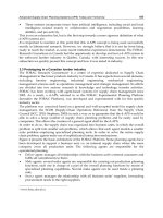
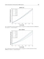
particles, they are usually designed for low inlet of changing the dimensions of an 8 inch diameter
velocities 5-10 feet per second (ft/sec). This is done to cyclones is shown in figure 6-11. The effects of
minimize erosion on the cyclone walls and to minimize changing gas inlet velocity, grain loading, particle
breakdown of coarser particles that would normally be specific gravity, gas viscosity, and particle size
separated, into particles too fine for collection. distribution on a 50 inch diameter cyclone are shown
e. Limited space. In cases where cyclones must be in figures 6-12 and 6-13. These figures illustrate the
erected in limited space, smaller diameter multi- dependence of cyclone collection efficiency on those
cyclones have an obvious space advantage over larger variables and the importance of maintaining proper gas
diameter units. Small cyclones also have the advantage inlet conditions.
of increased efficiency over a single unit handling the b. Field performance. The actual in-field perfor-
same gas capacity, although this advantage is some- mance of cyclone units will vary because of changes in
times lost by uneven gas distribution to each unit with operating conditions such as dust load and gas flow.
resultant fouling of some elements. Table 6-2 illustrates the optimum expected perform-
6-6. Cyclone performance application in combustion processes.
a. Collection efficiency and pressure drop. For any
given cyclone it is desirable to have as high a collection
efficiency and as low a pressure drop as possible.
Unfortunately, changes in design or operating variables
which tend to increase collection efficiency also tend to
increase pressure drop at a greater rate than the collec-
tion efficiency. Efficiency will increase with an increase
in particle size, particle density, gas inlet velocity,
cyclone body or cone length, and the ratio of body
diameter to gas outlet diameter. Decreased efficiency
is caused by an increase in gas viscosity, gas density,
cyclone diameter; gas outlet diameter; and inlet widths
or area. The effect on theoretical collection efficiency
ance of cyclone units for particulate removal
TM 5-815-1/AFR 19-6
6-13
6-7. Cyclone operation region must be maintained in order to eliminate a high
a. Erosion. Erosion in cyclones is caused by
impingement and rubbing of dust on the cyclone walls.
Erosion becomes increasingly worse with high dust
loading, high inlet velocities, larger particle size, and
more abrasive dust particles. Any defect in cyclone
design or operation which tends to concentrate dust
moving at high velocity will accelerate erosion. The
areas most subject to erosive wear are opposite the
inlet, along lateral or longitudinal weld seams on the
cyclone walls, near the cone bottom where gases
reverse their axial flow, and at mis-matched flange
seams on the inlet or dust outlet ducting. Surface irreg-
ularities at welded joints and the annealed softening of
the adjacent metal at the weld will induce rapid wear.
The use of welded seams should be kept to a minimum
and heat treated to maintain metal hardness. Continu-
ous and effective removal of dust in the dust outlet
circulating dust load and resultant erosion. The cyclone
area most subject to erosion is opposite the gas inlet
where large incoming dust particles are thrown against
the wall, and in the lower areas of the cone. Erosion in
this area may be minimized by use of abrasion resistant
metal. Often provisions are made from removable lin-
ings which are mounted flush with the inside surface of
the shell. Erosion resistant linings of troweled or cast
refractory are also used. Dust particles below the 5 to
10 micron range do not cause appreciable erosion
because they possess little mass and momentum. Ero-
sion is accelerated at inlet velocities above approx-
imately 75 ft/sec.
b. Fouling. Decreased collection efficiency,
increased erosion, and increased pressure drop result
from fouling in cyclones. Fouling generally occurs
either by plugging of the dust outlet or by buildup of
TM 5-815-1/AFR 19-6
6-14
materials on the cyclone wall. Dust outlets become sulfur oxides or hydrogen chloride are subject to acid
plugged by large pieces of extraneous material in the corrosion. Acids will form when operating at low gas
system, by overfilling of the dust bin, or by the break- temperatures, or when the dust hopper may be cool
off of materials caked on the cyclone walls. The enough to allow condensation of moisture. Corrosion
buildup of sticky materials on the cyclone walls is is usually first observed in the hopper or between
primarily a function of the dust properties. The finer or bolted sections of the cyclone inlet or outlet plenum
softer the dust, the greater is the tendency to cake on spaces where gasketing material is used and cool
the walls. Condensation of moisture on the walls will ambient air can infiltrate. Corrosion at joints can be
contribute to dust accumulations. The collector should minimized by using welded sections instead of bolted
therefore be insulated to keep the surface temperature sections. Ductwork and hoppers should be insulated
above the flue gas dew point. Wall buildup can and in cold climates the hoppers should be in a weather
generally be minimized by keeping the gas inlet protected enclosure. Heat tracing of the hoppers may
velocity above 50 ft/sec. be necessary.
c. Corrosion. Cyclones handling gases containing
TM 5-815-1/AFR 19-6
6-15
d. Dust hopper design. A properly designed dust recommended for ash containing unburned
hopper should be air tight and large enough to prevent combustibles or char for the same reason.
the dust level from reaching the cyclone dust outlets.
Dust hoppers are usually conical or pyramidal in shape 6-8. Selection of materials
and are designed to prevent dust buildup against the
walls. All designs should include a means of
continuous removal of dust from the hopper to a
storage bin, with an adequate alarm system to indicate
a malfunction. Bin level alarms are frequently used for
this purpose. On negative pressure systems, hoppers
and removal system must be air tight. If hot unburned
combustibles or char are present in the collected
particulate, introduction of fresh air can cause a hopper
fire. Pneumatic ash transport systems are not
a. Conditions. Cyclones can be constructed of a
variety of types of metals. The type of materials
specified is dependent upon the erosion characteristics
of the dust, the corrosion characteristics of the gases,
and the operating temperature of the cyclone.
Generally, cyclones are constructed of mild steel or
cast iron. (See para 7-5 for additional information on
materials selection for pollution control systems).
b. Erosion. Erosion is the single most important
criterion in specifying the materials for cyclone con-
TM 5-815-1/AFR 19-6
6-16
struction. Erosion life of a cyclone may be extended by 6-9. Advantages and disadvantages
using harder and thicker grades of steel. A stainless
steel of 400 Brinell rating or better is normally chosen
for cyclones subject to erosive conditions. When ero-
sion is extreme, it is necessary to provide for replacea-
ble liners in cyclone construction. Liners are made of
hard stainless steels or erosion resistant refractory. In
low temperature fly ash applications, cyclones of mild
steel or iron can be used because dust loadings are
generally too small to cause appreciable erosion. Cast
iron is most often used in multicyclones in boiler ser-
vice.
c. Temperature. Cyclones operated above 800
degrees Fahrenheit cannot be constructed of mild
steels because the metal will creep and form ridges or
buckled sections. Above 800 degrees Fahrenheit,
nickel-copper bearing steel such as Monel is used to
provide added strength. when temperatures are in
excess of 1000 degrees Fahrenheit, nickel-chromium
steel of the 400 series is used in conjunction with
refractory linings. Silica carbide refractories provide
excellent protection against erosion and high
temperature deformation of the cyclone metal parts.
a. Advantages. The advantages of selecting cyclones
over other particulate collection devices are:
— No moving parts,
— Easy to install and replace defective parts,
— Constructed of a wide variety of materials,
— Minimum space requirements,
— Designed to handle severe service conditions
of temperature, pressure, dust loading,
erosion, corrosion, and plugging,
— Can be designed to remove liquids from gas,
— Low capital costs,
— Low maintenance costs.
b. Disadvantages. The disadvantages of selecting
cyclones over other particulate collection devices are:
— Lower collection efficiency,
— Higher collection efficiencies (90-95 percent)
only at high pressure drops (6 inches, water
gauge),
— Collection efficiency sensitive to changes in
gas flow, dust load, and particle size
distribution,
— Medium to high operating costs.
TM 5-815-1/AFR 19-6
7-1
CHAPTER 7
HIGH AND LOW ENERGY SCRUBBER SYSTEMS
7-1. Scrubbers (2) Preformed spray scrubbers. A preformed
A scrubber utilizes a liquid to separate particulate or
gaseous contaminants from gas. Separation is achieved
through mass contact of the liquid and gas. Boiler
emissions to be controlled include fly ash and sulfur
oxides. Incinerator emissions to be controlled include
fly ash, sulfur oxides and hydrogen chloride.
7-2. Types of scrubbers
a. Low energy scrubbers. Low energy scrubbers are
more efficient at gaseous removal than at particulate
removal. A low energy scrubber utilizes a long liquid-
gas contact time to promote mass transfer of gas. Low
energy scrubbers depend on extended contact surface
or interface between the gas and liquid streams to
allow collection of particulate or gaseous emissions.
(1) Plate-type scrubbers. A plate-type scrubber
consists of a hollow vertical tower with one
or more plates (trays) mounted transversely
in the tower (figure 7-1). Gas comes in at the
bottom of the tower; and must pass through
perforations, valves, slots, or other openings
in each plate before exiting from the top.
Liquid is usually introduced at the top plate,
and flows successively across each plate as
it moves downward to the liquid exit at the
bottom. Gas passing through the openings in
each plate mixes with the liquid flowing over
the plate. The gas and liquid contact allows
the mass transfer or particle removal for
which the plate scrubber was designed.
Plate-type scrubbers have the ability to
remove gaseous pollutants to any desired
concentration provided a sufficient number
of plates are used. They can also be used for
particle collection with several sieve
(perforated) plates combining to form a
sieve-plate tower. In some designs, impinge-
ment baffles are placed a short distance
above each perforation on a sieve plate,
forming an impingement plate upon which
particles are collected. The impingement
baffles are below the level of liquid on the
perforated plates and for this reason are
continuously washed clean of collected
particles. Particle collection efficiency is
good for particles larger than one mircron in
diameter. Design pressure drop is about 1.5
inches of water for each plate.
spray scrubber (spray tower) is a device
which collects particles or gases on liquid
droplets and utilizes spray nozzles for liquid
droplet atomization (figure 7-2). The sprays
are directed into a chamber suitably shaped
to conduct the gas through the atomized
liquid droplets. Spray towers are designed
for low pressure drop and high liquid
consumption. They are the least expensive
method for achieving gas absorption because
of their simplicity of construction with few
internals. The operating power cost is low
because of the low gas pressure drop. Spray
towers are most applicable to the removal of
gases which have high liquid solubilities.
Particle collection efficiency is good for
particles larger than several microns in
diameter. Pressure drops range from 1 to 6
inches, water gauge.
(3) Centrifugal scrubbers. Centrifugal scrubbers
are cylindrical in shape, and impart a
spinning motion to the gas passing through
them. The spin may come from introducing
gases to the scrubber tangentially or by
directing the gas stream against stationary
swirl vanes (figure 7-2). More often, sprays
are directed through the rotating gas stream
to catch particles by impaction upon the
spray drops. Sprays can be directed outward
from a central spray manifold or inward
from the collector walls. Spray nozzles
mounted on the wall are more easily
serviced when made accessible from the out-
side of the scrubber. Centrifugal scrubbers
are used for both gas absorption and particle
collection and operate with a pressure drop
ranging from 3 to 8 inches, water gauge.
They are inefficient for the collection of
particles less than one or two microns in
diameter.
(4) Impingement and entrainment scrubbers.
Impingement and entrainment scrubbers
employ a shell which holds liquid (figure 7-
3). Gas introduced into a scrubber is
directed over the surface of the liquid and
atomizes some of the liquid into droplets.
These droplets act as the particle collection
and gas absorption surfaces. Impingement
and entrainment scrubbers are most
TM 5-815-1/AFR 19-6
7-2
frequently used for particle collection of keeps the packing elements clean. Moving
particles larger than several microns in bed scrubbers are used for particle collection
diameter. Pressure drops range from 4 to 20 and gas absorption when both processes
inches, water gauge. must be carried out simultaneously. Particle
(5) Moving bed scrubbers. Moving bed collection efficiency can be good down to
scrubbers provide a zone of mobile packing particle sizes of one micron. Gas absorption
consisting of plastic, glass, or marble spheres and particulate collection are both enhanced
where gas and liquid can mix intimately when several moving bed stages are used in
(figure 7-3). A cylindrical shell holds a series. Pressure drops range from 2.5 to 6
perforated plate on which the movable inches water gauge per stage.
packing is placed. Gas passes upward b. High energy scrubbers. High energy scrubbers
through the perforated plate and/or down utilize high gas velocities to promote removal of parti-
over the top of the moving bed. Gas cles down to sub-micron size. Gas absorption efficien-
velocities are sufficient to move the packing cies are not very good because of the co-current
material when the scrubber is operating movements of gas and liquid and resulting limited gas/
which aids in making the bed turbulent and liquid contact time.
TM 5-815-1/AFR 19-6
7-3
(1) Venturi scrubbers. The venturi scrubber uti- good for particles larger than a micron in
lizes a moving gas stream to atomize and diameter. Gas absorption efficiency is low
accelerate the liquid droplets (figure 7-4). A because of the co-current nature of the gas
convergent-divergent nozzle is used to and liquid flow. Liquid pumping power
achieve a gas velocity of 200 to 600 feet per requirements are high and capacity is low
second (ft/ sec) which enhances liquid making this type impractical for boiler or
atomization and particulate capture. incinerator emissions control.
Collection efficiency in a gas atomized (3) Dynamic (wetted fan) scrubber This
venturi scrubber increases with pressure scrubber combines a preformed spray,
drop. Pressure drops of 25 inches water packed bed or centrifugal scrubber with an
gauge or higher are utilized to collect sub- integral fan to move the gas stream through
micron particles. Scrubbers of the gas the scrubber. Liquid is also sprayed into the
atomized type have the advantage of adjust- fan inlet where the rotor shears the liquid
ment of pressure drop and collection into dispersed droplets. The turbulence in
efficiency by varying gas velocity. The gas the fan increases liquid/ gas contact. This
velocity is controlled by adjusting the area of type of scrubber is effective in collection of
the venturi throat. Several possible methods fine particulate. Construction of this
for doing this are illustrated in figure 7-5. scrubber is more complex due to the neces-
This can be used to control performance sity of the fan operating in a wet and possibly
under varying gas flow rates by maintaining corrosive gas stream. The design must
a constant pressure drop across the venturi prevent build-up of particulates on the fan
throat. Due to the absence of moving parts, rotor.
scrubbers of this type may be especially c. Dry scrubbers. Dry scrubbers are so named
suitable for the collection of sticky particles. because the collected gas contaminants are in a dry
Disadvantages include high pressure drop form.
for the collection of sub-micron particles and (1) Spray dryer. The spray dryer is used to
limited applicability for gas absorption. remove gaseous contaminants, particularly
(2) Ejector venturi. The ejector venturi scrubber sulfur oxides from the gas stream. An
utilizes a high pressure spray to collect parti- alkaline reagent slurry is mechanically
cles and move the gas. High relative velocity atomized in the gas stream. The sulfur
between drops and gas aids in particle oxides react with the slurry droplets and are
collection. Particle collection efficiency is absorbed into the droplets. At the same time,
TM 5-815-1/AFR 19-6
7-4
the heat in the gas stream evaporates the to as a dry scrubber, is more a filter using
water from the droplets leaving a dry sized gravel as the filter media. A bed of
powder. The gas stream is then passed gravel is contained in a vertical cylinder
through a fabric filter or electrostatic between two slotted screens. As the gas
precipitator where the dry product and any passes through the interstices of the gravel,
fly ash particulate is removed. The scrubber particulates impact on, and are collected on
chamber is an open vessel with no internals the gravel surface. Sub-micron size particles
other than the mechanical slurry atomizer are also collected on the surface because of
nozzles. The vessel is large enough to allow their Brownian movement. Dust-laden
complete drying of the spray before gravel is drawn off the bottom and the dust
impinging on the walls and to allow enough is separated from the gravel by a mechanical
residence time for the chemical reaction to vibrator or pneumatic separator. The cleaned
go to completion. A schematic of the system gravel is then conveyed up and dumped on
is shown in figure 7-6. Refer to chapters 8 top of the gravel bed. The cylindrical bed
and 9 for discussion of the fabric filter or slowly moves down and is constantly
electrostatic precipitator. recycled.
(2) Gravel bed. The gravel bed, while referred