Air Pollution Control Systems for Boiler and Incinerators Part 10 docx
Bạn đang xem bản rút gọn của tài liệu. Xem và tải ngay bản đầy đủ của tài liệu tại đây (117.88 KB, 10 trang )
TM 5-815-1/AFR 19-6
11-5
c. Copper oxide is used as the acceptor for SO
2
removal, forming copper sulfate. Subsequently both
the copper sulfate which was formed and the copper
oxide catalyze the reduction of NO to nitrogen and
water by reaction with ammonia. A regeneration step
produces an SO rich steam which can be used to man-
2
ufacture by-products such as sulfuric acid.
11-5. Step-by-step NO reduction method
x
a. Applicability. The application of NO reduction
x
techniques in stationary combustion boilers is not
extensive. (However, NO reduction techniques have
x
been extensively applied on automobiles.) These tech-
niques have been confined to large industrial and utility
boilers where they can be more easily implemented
where NO emissions standards apply, and where
x
equipment modifications are more economically justi-
fied. However some form of NO control is available
x
for all fuel-burning boilers without sacrificing unit
output or operating efficiency. Such controls may
become more widespread as emission regulations are
broadened to include all fuel-burning boilers.
b. Implementation. The ability to implement a par-
ticular combustion modification technique is dependent
upon furnace design, size, and the degree of equipment
operational control. In many cases, the cost of con-
version to implement a modification such as flue-gas
recirculation may not be economically justified. There-
fore, the practical and economic aspects of boiler
design and operational modifications must be
ascertained before implementing a specific reduction
technique.
(1) Temperature reduction through the use of
two stage combustion and flue-gas
recirculation is most applicable to high heat
release boilers with a multiplicity of burners
such as utility and large industrial boilers.
(2) Low excess air operation (LEA) coupled with
flue-gas recirculation offers the most viable
solution in smaller industrial and commercial
size boilers. These units are normally
designed for lower heat rates (furnace
temperature) and generally operate on high
levels of excess air (30 to 60%).
c. Compliance. When it has been ascertained that
NO emissions must be reduced in order to comply
x
with state and federal codes, a specific program should
be designed to achieve the results desired. The
program direction should include:
— an estimate of the NO reduction desired,
x
— selection of the technique or combination
thereof, which will achieve this reduction;
— an economic evaluation of implementing each
technique, including equipment costs, and
changes in operational costs;
— required design changes to equipment
— the effects of each technique upon boiler
performance and operational safety.
d. Procedure. A technical program for implementing
a NO reduction program should proceed with the aid
x
of equipment manufacturers and personnel who have
had experience in implementing each of the NO
x
reduction techniques that may be required in the
following manner:
(1) NO emission test. A NO emission test
x x
should be performed during normal boiler
load times to ascertain actual on-site NO
x
generation. This test should include recording
of normal boiler parameters such as: flame
temperature; excess air; boiler loads; flue-gas
temperatures; and firing rate. These
parameters can be referred to as normal
operating parameters during subsequent
changes in operation.
(2) Reduction capabilities. The desired reduction
in NO emissions, in order to comply with
x
standards, should be estimated based on mea-
sured NO emission data. Specific NO re-
x x
duction techniques can then be selected based
on desired reductions and reduction capa-
bilities outlined in preceding paragraph 11-3.
(3) Equipment optimization. Any realistic pro-
gram for NO reduction should begin with an
x
evaluation and overhaul of all combustion
related equipment. A general improvement of
boiler thermal efficiency and combustion effi-
ciency will reduce the normal level of NO
x
emissions. Of major importance are:
(a) the cleanliness of all heat transfer surfaces
(especially those exposed to radiative heat
absorption),
(b) maintaining proper fuel preparation (siz-
ing, temperature, viscosity),
(c) insuring control and proper operation of
combustion equipment (burners nozzles,
air registers, fans, preheaters, etc.),
(d) maintaining equal distribution of fuel and
air to all burners.
(4) Low excess air operation. Low excess air
operation is the most recommended modific-
ation for reducing NO emission. Possible
x
reductions are given in preceding table 11-2.
How-ever, a control system is needed to
accurately monitor and correct air and fuel
flow in response to steam demands. Of the
control systems available, a system incorpo-
rating fuel and air metering with stack gas O
2
correction will provide the most accurate
control. A system of this nature will generally
pay for itself in fuel savings over a 2 to 3-year
period, and is economically justified on
industrial boilers rated as low as 40,000 lb of
steam/hr.
(5) Flue-gas recirculation. Flue-gas recirculation
is the second most effective NO reduction
x
technique for boilers where two stage
combustion cannot be applied. Low excess
TM 5-815-1/AFR 19-6
11-6
air operation and flue-gas recirculation must design must accompany any application of
be implemented simultaneously from a design flue-gas recirculation which effectively lowers
point of view. LEA operation may require furnace temperature and thus, radiative heat
installation or retrofitting of air registers to transfer. Convective heat transfer is also
maintain proper combustion air speed and increased by increased gas flow due to the
mixing at reduced levels or air flow. Flue gas dilution of combustion air. It is advisable to
recirculation will require larger air registers to consult boiler manufacturers as to the
accommodate the increased volume of flow. applicability of flue-gas recirculation to their
Therefore, simultaneous application of LEA furnaces.
operation and flue-gas recirculation may e. Summary. The potential and applicability of each
minimize the need for redesign of burner air NO reduction technique is summarized in table 11-4.
registers. Knowledge of furnace thermal
x
TM 5-815-1/AFR 19-6
11-7
TM 5-815-1/AFR 19-6
12-1
CHAPTER 12
EMISSION CONTROL EQUIPMENT SELECTION FOR INCINERATORS
AND BOILERS
12-1. Principles of selection proximate properties and an analysis of the
a. Selection of emission control equipment is made
in three basic steps.
(1) Performance. The control equipment must be
capable of continuously controlling the emis-
sion of the pollutant below the permitted
quantities. The equipment type and design
should have a proven record of meeting the
required removal or collection efficiency and
the manufacturer should guarantee the
equipment for continuous performance.
(2) Construction. The materials of construction
should be compatible with the characteristics
and constituents in the flue gases. Materials
should be resistant to erosion and corrosion
and should be suitable for the operating tem-
peratures. The unit should have adequate
access manholes and service platforms and
stairs to inspect and maintain the equipment.
Units should be adequately insulated and
weather protected.
(3) Operation. Where more than one design or
type of device can provide the necessary
pollution control it then becomes necessary to
evaluate the various designs based on a life-
cycle cost-analysis, and the ease of operation.
b. Preliminary information which is needed to prop-
erly select pollution control equipment are as follows:
(1) Site-specific emissions limitations for the
stack serving the particular boiler or
incinerator must be determined for the
applicable source and ambient condition. This a. Gas properties influence the design and perfor-
information is to be derived from existing mance of the pollution control equipment. When work-
federal, state and local regulations. ing with a particular emission standard or code the gas
(2) Obtain detailed descriptions of the boiler or properties must be converted to the units used in the
incinerator including the combustion control codes, such as lbs per million BTU; gr/ACFM;
system(s) and all support auxiliaries including DSCFM at 32; DSCFM at 68; DSCFM corrected to 8
outline drawings available from the manufac- percent 0 .
turers; and the predicted uncontrolled, gas- b. Flow rate. The flow-rate of exhaust gases gener-
eous emissions established for the units. ated in the combustion process must be measured or
(3) For the particular fuel to be burned, calculated to determine the required volumetric size of
determine the method of firing and maximum the collection equipment. Flow-rate variations result in
continuous rated heat input per British velocity changes and thus influence collector efficiency
Thermal Units per hour (BTU’s/Hr) along and pressure drop. It is necessary therefore to obtain
with applicable combustion calculations for maximum, average, and minimum values for a cyclical
normal and upset operating conditions. This or modulating operation.
may require a fuel analysis. In the case of coal c. Temperature. Gas temperature affects gas volume
firing the analysis should include ultimate and (and simultaneously collector volume) and materials of
residual ash.
(4) Obtain required construction and operations
permit forms from applicable regulatory
agencies, complete, and submit where
required.
(5) Obtain the requirements and restraints for dis-
posing of the collected pollutant. Under some
circumstances such as preliminary studies it
becomes necessary to calculate the process
data and then use empirical data to estimate
the emission quantities.
c. The U.S. Environmental Protection Agency (EPA)
has published a Technical Manual 'AP-42" and
excerpts from the EPA publication have been
reproduced and included in Chapters 2 and 3 of this
manual to be used as a guide for predicting the emis-
sions that will be generated by various fuels and com-
bustions apparatus.
d. Present emissions control requirements and laws
are complicated and stringent, and emission control
equipment represents a significant portion of the com-
bustion equipment costs. Inadequately specified or
applied control devices could be a very costly error. It
is advisable wherever possible to utilize qualified engi-
neers experienced in boiler or incinerator plant designs
and operation of such tasks. It is beneficial for the
engineer to also have experience in securing necessary
permits.
12-2. Flue gas properties
2
TM 5-815-1/AFR 19-6
12-2
construction for the collector. Temperature may also
limit use of certain collectors. For instance, tem-
peratures above 550 degree Fahrenheit rule out the use
of fabric filters.
d. Pressure. Carrier gas pressure must be known or
calculated to determine the structural requirements for
the collector under operating and upset conditions.
e. Viscosity. Gas viscosity is a measure of molecular
activity in a gas stream. The greater the gas viscosity,
the greater the resistance to particle migration across
the stream normal to gas flow. Since gas viscosity
increases with gas temperature, it is an important factor
in the performance of dry particulate collection
devices. viscosity effects can be minimized if equip-
ment is properly specified.
f. Moisture content. Moisture content affects the
performance of collection equipment and the choice of
construction materials. It is important to know the dew
point of the exhaust gas, as temperatures below dew
point allows acid vapors to condense and attack struc-
tural surfaces. This is a particular concern with boiler
flue-gas which often contains a significant amount of
sulfuric acid vapor.
g. Chemical composition. Chemical composition
primarily affects the choice of construction materials
for a collector. Collectors must be suitably protected to
handle corrosive gases.
h. Toxicity. Handling of toxic gases requires special
treatment and equipment and must be reviewed on an
individual basis. This manual does not address incin-
eration of toxic or hazardous wastes.
12-3. Particulate properties
a. Particulate properties that must be determined for
control equipment selection and design are described
below. Appropriate test methods are listed in table 5-1.
b. Concentration (loading). Particulate loading is a
measurement of particulate concentration in flue gases
(see this manual, chapters 2 and 3) expressed in grains
per cubic foot. Particulate loading is used as a criteria
to design and select applicable collection equipment.
Fluctuations in loading (for example: soot blowing in
boilers) must be noted and maximum, minimum, and
average values should be recorded. High grain loadings
may require a series system of control devices to meet
particulate emissions and air quality standards. For
instance, a cyclone followed by an electrostatic pre-
cipitator or baghouse.
c. Particle size. The particle size analysis affects the
collection efficiency for each control device. Fine par-
ticulate collection requires high-efficiency equipment
such as venturi scrubbers, electrostatic precipitators, or
fabric filters.
d. Resistivity. Particulate resistivity is a limiting
factor in the design of electrostatic precipitators.
Resistivity must be determined if an electrostatic pre-
cipitator is to be selected to control particulate emis-
sions. As a general guideline, resistivity above 1010
ohm-cm normally rules out the use of electrostatic pre-
cipitation unless provisions are made for particulate
electrical conditioning.
e. Handling characteristics. Particle-handling
characteristics influence dust-handling systems (duct-
work, collector structure, hoppers, conveyors) and
materials of construction. Dust-handling characteristics
include flow properties, abrasiveness, hygroscopicity,
moisture content, agglomerating tendencies. These
properties, including specific gravity and bulk density
should be evaluated in the design of a dust-collecting
system.
f. Chemical composition. Chemical composition of
particulate affects materials of construction and design
of the collector and ash disposal equipment as does
carrier gas composition.
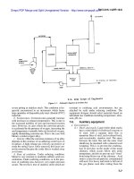
12-4. Application of emission control sys-
tems for boilers.
As a result of current, stringent, stack emission regula-
tions, applications of certain conventional emissions
control systems have evolved that provide satisfactory
performance when properly sized and specified. Refer-
enced are CFR40 part 60 for new source performance
standards (NSPS) only, as ambient regulations have
wide variation from site-to-site requiring investigation
for each location. Following is a brief description of the
most common combustion sources, fuels, and control
devices employed:
a. Natural gas fired power boiler. NSPS cover par-
ticulates; sulfur dioxide SO ; nitrogen dioxide NO ;
2 x
and opacity.
(1) External devices are not usually required.
Properly adjusted combustion controls,
burner(s), furnace designs, and gas monitor-
ing are sufficient to meet the performance
standards.
(2) Even though natural gas is a relatively clean
fuel, some emissions can occur from the
combustion reaction. For example, improper
operating conditions, including items such as
poor mixing and insufficient air, may cause
large amounts of smoke, carbon monoxide,
and hydrocarbons to be produced. Moreover,
because a sulfur-containing mercaptan is
added to natural gas for detection proposes,
small amounts of sulfur oxides will also be
produced in the combustion process.
(3) Nitrogen oxides are the major pollutants of
concern when burning natural gas. Nitrogen
dioxide emissions are a function of the tem-
perature in the combustion chamber and the
rate of cooling of the combustion products.
TM 5-815-1/AFR 19-6
12-3
Emission levels generally vary considerably
with the type and size of unit and are also a
function of loading.
(4) In some large boilers, several operating modi-
fications have been employed for NO
x
control. In staged combustion, for example,
including off-stoichiometric firing, also called
"biased firming," some burners are operated
fuel-rich, some fuel-lean, while others may
supply air only. In two-staged combustion,
the burners are operated fuel-rich (by
introducing only 80 to 95 percent
stoichiometric air) with combustion being
completed by air injected above the flame
zone through second-stage “NO -ports”. In
x
staged combustion, NO emissions are
x
reduced because the bulk of combustion
occurs under fuel-rich, reducing conditions.
b. Distillate oil fired power boilers. NSPS cover par-
ticulates; SO ; NO ; and opacity. Methods of modifying
2 x
or controlling emissions are discussed in the following.
(1) Particulate. The user should note that in most
cases external pollution control devices are
not required for boilers firing No.1 or No.2
fuel oils.
(2) SO . Most distillates will contain sulfur quan-
x
tities low enough so that no treatment will be
necessary. However, a fuel analysis must be
reviewed as some distillates can have as much
as one percent sulfur. When the sulfur content
produces SO emissions in excess of the
2
allowable a wet scrubbing system will be
required.
(3) NO . Control requires the proper combustion
x
controls, and burners and furnaces designed
to limit NO generation from high combustion
x
temperatures. Usually NO reductions are
x
accomplished by limiting excess air firing and
staged combustion. Large utility system units
sometimes also employ flue-gas recirculation
in addition to the other methods.
(4) Opacity. This may be controlled by proper
air-fuel ratios; good combustion controls;
limiting particulate emissions; and proper
engineering design of the burners and furnace
chamber.
c. Residual oil fired power boilers. NSPS cover par-
ticulates; SO ; NO ; and opacity. Methods of modifying
2 x
or controlling emissions are discussed in the following.
(1) Particulate control.
(a) When using low-sulfur oils, cyclonic
mechanical collectors are usually
adequate. On larger utility size units
electrostatic precipitators are employed to
limit particulate emissions.
(b) For emissions from combustion of high-
sulfur oils a wet scrubbing system can be
used for both SO removal and
2
particulate control.
(2) SO . Use wet scrubbing system with a low
2
pressure drop.
(3) NO . May be controlled by utilizing limited
x
excess-air firing; flue gas recirculation; staged
combustion; or combinations of these.
(4) Opacity. May be controlled by limiting or col-
lecting the particulates and by properly
adjusted and designed combustion controls
with good burner and furnace designs.
d. Pulverized coal-fired power boiler. NSPS cover
limitations for particulates; SO ; NO ; and opacity.
2 x
Methods of modifying or controlling emissions are dis-
cussed in the following.
(1) Particulates.
(a) Control by use of electrostatic
precipitator
(b) Control by use of fabric filters
(c) Control by use of venturi scrubber
(d) Control by combination of a mechanical
collector followed by either (a), (b), or
(c), above
(2) SO .
2.
(a) Use suitable wet scrubber (can double for
both SO and particulates)
2
(b) Use suitable dry scrubber followed by
fabric filters or electrostatic precipitator
(c) Selection of a wet or dry scrubbing
system is determined by evaluating the
economics (installation and operating
costs) and the disposal of the collected
pollutant.
(3) NO . Ensure that the burner and furnace are
x
designed for limited excess-air firing and
staged combustion. In some cases it may be
necessary to have a second stage air fan
designated as an NO control fan in order to
x
gain compliance.
(4) Opacity. This may be controlled by
particulate removal and properly adjusted
combustion controls. In some cases this could
be the more stringent requirement for
particulate removal.
e. Spreader and mass feed stoker coal fired boilers
with a traveling grate. NSPS cover limitations for par-
ticulates; SO ; NO ; and opacity. Methods of modifying
2 x
or controlling emissions are discussed in the following.
(1) Particulates.
(a) Control by use of electrostatic precipitator
(b) Control by use of suitable fabric filter
(c) Control by use of suitable wet scrubber
(d) Control by a combination of a mechanical
collector followed by either (a), (b), or
(c) above
(2) SO .
2
(a) Use suitable wet scrubber (can double for
both SO and particulate).
2
(b) Use suitable dry scrubber followed by
either a fabric filter or an electrostatic
precipitator
TM 5-815-1/AFR 19-6
12-4
(3) NO . Control by specifying furnace and com- when ponding is not viable. The dry ash
x
bustion air controls designed to maintain lim- should be cooled and conditioned with
ited flame temperatures under operating con- water before being transported for land
ditions. fill disposal.
(4) Opacity. Control by particulate removal and g. Coal fired fluidized bed boilers. NSPS cover lim-
properly adjusted combustion controls. This itation for particulates; SO ; NO ; and opacity. Meth-
can be the more stringent requirement for ods of modifying or controlling emissions are discussed
particulate removal. in the following.
f. Wood waste and bark fired boilers. NSPS cover (1) Particulates. Control by use of fabric filter or
limitation for particulates and opacity. Methods of an electrostatic precipitator. Most units will
modifying or controlling emissions are discussed in the not require a mechanical collector in series
following. with the baghouse or electrostatic
(1) Particulates. precipitator. However, if high dust loadings
(a) Control by use of a mechanical collector are anticipated an in-line mechanical collector
followed by either a scrubber or an elec- in series with the baghouse or electrostatic
trostatic precipitator. precipitator may be justified.
(b) Control by use of wet scrubber. (2) SO . Controlled by the metering (feeding) of
(c) Control by use of electrostatic lime stone into the fluidized fuel bed.
precipitator. (3) NO . The comparatively low furnace tem-
(d) Control by use of gravel bed filter. peratures experienced in fluidized bed boilers
(2) Opacity. Opacity is controlled by particulate limits the heat generated NO formation. No
collection and properly adjusted combustion special devices or controls are required for
controls. The "as-fired" condition of wood NO control on fluidized bed units.
waste fuel will impact the choice of (4) Opacity. Controlled by particulate removal
particulate control equipment. and properly adjusted and designed
(a) Hogged bark and wood chips with 45% combustion controls.
to 55% moisture usually require a (5) Ash handling and removal systems. Can be
mechanical collector followed by a dry or wet and may be automated cycles or
scrubber or an E SP. Material collected in continuous ash removal utilizing equipment
the mechanical collector is a combination and methods previously discussed.
of char, ash, and sand. The material is
classified to separate the char from the 12-5. Municipal solid waste-fired boilers
ash/sand mixture so the char can be (MSW) and boilers using refuse
reinjected into the furnace combustion derived fuels(RDF)
zone. The ash/sand mixture is discharged
by gravity or conveyor to a holding tank
which can be either wet or dry. All ash-
hopper discharge openings must be pro-
tected from air infiltration by rotary-seal
discharge valves or an air-lock damper
arrangement, to prevent ignition of hot
combustibles.
(b) Dry wood wastes that are chipped to less
than 1" x ½” size may not require the
mechanical collector and reinjection
equipment. Gas clean-up equipment of
choice may then be either the scrubber or
electrostatic precipitator. Ash discharge
hoppers need to be protected by seal
valves or air locks in all cases.
(c) Fabric filters are avoided because of the
potential for burning the fabric with hot
char carry over.
(d) Ash handling is usually accomplished
using a hydraulic conveying system
discharging to an ash settling pond.
(e) Screw conveyors or drag-chain conveyors
are acceptable alternatives for dry
handling of ash from wood-fired boilers
2 x
2
x
x
x
a. Municipal solid waste fired boilers fall in the same
emission regulation category as an incinerator. Com-
pliance is only required for particulate emission regula-
tions.
b. Boilers using refuse derived fuels must meet the
incinerator regulations and are also required to meet
emission standards for any other fuels fired in the
boiler. In most states the allowable emissions are
calculated on the ratio of fuels fired and which cover
control of particulate, SO , NO , and opacity.
2 x
(1) Particulats Use mechanical collectors as a
primary device followed by either a fabric
filter or an electrostatic precipitator. The ESP
is favored when there is co-firing with coal in
the MSW boiler. Without coal co-firing,
resistivity of the particulate can be extremely
high. Wet scrubbers should be avoided
because of possible odor pick up.
(2) SO . SO formation is a function of the sulfur
2 2
content in the refuse and fuel. In most cases
no SO removal devices are necessary.
2
However, when required a dry scrubber
system followed by either a baghouse or an
electrostatic precipitator is preferred.
TM 5-815-1/AFR 19-6
12-5
(3) NO . Furnace design and firing methods are (3) When particulates are the controlled
x
used to limit NO . Two-step combustion is pollutant, primary collection devices
x
employed. The primary zone is fired with lim- commonly used are: after-burners;
ited air to maintain a reducing atmosphere mechanical collectors; wetted baffles; and
and the secondary zone uses an oxidizing spray chambers.
atmosphere to provide a controlled low-tem- (4) The final collection fo small particulate mate-
perature flame with minimum excess air. rial is usually accomplished with one of the
(4) Opacity. Opacity is controlled by limiting par- following devices:
ticulate emissions and by properly designed — venturi or orifice-type scrubber -electrostatic
combustion controls. precipitator
12-6. Applications of emission control c. Incinerator vapor and odor control. Objection-
systems for incinerators able vapors and odors in incinerator exhaust streams
Refuse incinerators are type categorized as: municipal;
industrial; commercial; and sludge. NSPS cover par-
ticulate emissions only. However, incineration of many
solid, liquid, and gaseous wastes will produce noxious
gases that require special treatment.
a. Municipal incinerators. Optimum control of
incinerator particulate emissions begins with proper
furnace design and careful operation. A proper design
includes: a furnace/grate system appropriate to the
waste; an adequate combustion gas retention time and
velocity in the secondary combustion chamber; a suit-
able underfire and overfire air system; and establishing
the optimum underfire/overfire air ratios.
(1) for compliance with NSPS it is necessary to
utilize gas cleaning equipment and to
optimize operating conditions for the furnace.
(2) Particulates. May be controlled with mechan-
ical collectors; settling chambers; after
burners; and low efficiency scrubbers used as
precleaners. These must be followed by an
electrostatic precipitator or a high efficiency
venturi/orifice scrubber for final cleaning.
Fabric filters may be used if emissions gas
temperature is maintained below the
maximum temperature rating of fabric media
being used. This will usually require water
spray injection for evaporative cooling of the
gas stream.
(3) Odor control is frequently required and can
be accomplished with after-burners
strategically located in the furnace to oxidize
the odorous gases.
b. !Industrial and commercial incinerators. Design
of the incinerators and emissions control requirements
are greatly influenced by the composition of the solid
waste that is incinerated.
(1) Single chamber and conical (Teepee) type
incinerators will not meet current NSPS emis-
sion requirements.
(2) Multiple chamber incinerators with
controlled-combustion features, and
fluidized-bed incinerators including sludge
incinerators may be equipped with one or
more of the previously discussed or following
gas-cleaning systems to meet NSPS.
— fabric filter.
sometimes necessitate specialized control systems.
Odorous components present downstream of con-
ventional cleaning systems are usually organic in gas-
eous or fine particulate form. Several methods
available for their control are discussed below.
(1) Afterburners. Direct thermal incineration can
be utilized to oxidize odorous fumes. A fume
incineration system, or afterburner, basically
consists of a gas or oil-fired burner mounted
to a refractor-lined steel shell. Odorous
vapors and particulate matter are exposed to
a high temperature flame (1200 to 1400
degrees Fahrenheit) and are oxidized into
water vapor and carbon dioxide. The
principal advantages of direct thermal
incineration of odorous pollutants are
simplicity, consistent performance, easy
modification to accommodate changes in
standards, and ease of retrofit. The major dis-
advantage is the uncertainty and expense of
fuel supply usually natural gas.
(2) Vapor condenser. Vapor condensers are uti-
lized to control obnoxious odors, particularly
m processes where the exhaust gases contain
large quantities of moisture. Condensers can
be either the direct contact type, or shell and
tube surface condensers. The resulting con-
densate is rich in odorous material and can be
sewered of treated and disposed of by other
conventional methods. (See paragraph 7-4 for
further information on treatment and disposal
of waste materials.) Condensers are often
used in conjunction with an afterburner. In
such a system, exhaust gases are condensed
to ambient temperature before incineration,
reducing gas stream volume by as much as 95
percent and reducing moisture content.
Lowering gas volume and moisture content
can substantially reduce the cost and fuel
requirements of the afterburner assembly.
(3) Catalytic oxidation. Incineration of odorous
pollutants in the presence of a suitable
catalyst can lower the temperature required
for complete combustion and reduce the
overall reaction time. Advantages of catalytic
oxidation are:
TM 5-815-1/AFR 19-6
12-6
— Smaller units required because lower gas may, in certain cases, preclude the use of
temperatures reduce gas volume, otherwise satisfactory equipment.
— Less oxygen required in the effluent stream (5) Refuse disposal needs. Methods of removal
since catalyst promotes efficient use of oxy- and disposal of collected materials will vary
gen, with the material, plant process, quantity
— Lower NO emissions due to lower flame involved, and collector design (chap 6, 7, and
x
temperatures and reduced oxygen loads. 9). Collectors can be unloaded continuously,
(4) The principle disadvantages are: or in batches. Wet collectors can require
— High initial capital equipment costs additional water treatment equipment and if
— Periodic replacement of expensive catalysts the pollutation control device uses water
(5) Absorbers. Absorption systems for odor con- directly or indirectly, the supply and disposal
trol involve the use of selected liquid absor- of used water must be provided for.
bents to remove odorous molecules from
effluent gases. The gas to be absorbed should 12-8. Tradeoffs and special considerations
have a high solubility in the chosen absorbent
or should react with the absorbing liquid.
Various methods are used to affect intimate
contact of liquid absorbent and gaseous
pollutant.
12-7. Technical evaluation of control
equipment
a. Given the site-specific ambient air quality centration design may not satisfy high emissions at
requirements, and the NSPS emissions limitations, and start-up or shut-down. Cyclic operation could also lead
then comparing them with the uncontrolled emissions to problems in terms of equipment performance rela-
data for the combustor, it becomes possible to make a tive to high or low temperatures and volumes. Duct-
selection of various emissions controls systems to meet work providing good gas distribution arrangements for
the emission restraints. Required is a knowledge of the a specific volume could cause significant problems if
various emissions control devices and their application the gas volume were to increase or decrease.
to specific problems including their sizing and b. Reliability of equipment. Since particulate control
operation. equipment is relatively expensive, and due to the fact
b. Other factors which must be evaluated in selecting that it is usually an integral part of the power
control equipment include: site compatibility; dis- generation process, it is of utmost importance that the
position of the collected pollutant; installation and equipment provide reliable service. Wrong choices of
operation costs; maintainability; and the ability to fabric for fabric filters; wrong materials of construction
provide continuous protection during operation of the for wet scrubbers; the wrong choice of a multicyclone
combustion units. Tables 12-1 and 12-2 offer a com- to achieve high efficiency on fine particles; can all lead
parison of these characteristics to serve as an aid in the to collector outages, or complete failure. Collector
final determination of the best control system for a failures may be accompanied by a loss of production or
particular application. by expensive replacement with new devices. Evalua-
c. Specific operating characteristics that should be tion trade-offs should be made between costs for an
compared in evaluating suitable collection equipment auxiliary control unit and the cost of shutting down the
are listed below. Each control device section of this entire process due to collector failure.
manual should be consulted for specific descriptions of c. Space allowance. Special consideration by the
various control equipment. design engineer must be given to provide space in the
(1) Temperature and nature of gas and particles. planned plant layout for adding more pollution control
Collection equipment must be compatible equipment in the future. Future plant modifications will
with operating temperatures and chemical in most cases have to meet more stringent standards
composition of gas and particles. than the existing NSPS.
(2) Collector pressure loss. The power require- d. Gas cooling. When high temperature (greater than
ment for gas-moving fans can be a major cost 450 degrees Fahrenheit) exhaust gasses are being
in air pollution control. handled, a study should be made on the cost of install-
(3) Power requirement. Electrostatic pre- ing equipment to operate at the elevated temperature
cipitators, scrubbers, and fabric filters have versus the cost and effects of gas cooling.
additional electrical requirements beside fan e. Series operation of collectors. Dust collectors
power. may be used in series operation for the following
(4) Space requirement. Some control equipment reasons:
requires more space than others. This factor (1) A primary dust collector acts as a precleaner
a. Design considerations. In order to design equip-
ment to meet air pollution control requirements, the
top output or maximum ratings should be used in the
selection of control equipment. The additional cost for
extra capacity is negligible on the first cost basis, but a
later date addition could cost a substantial sum. It
should also be noted whether the dust-generating pro-
cess is continuous or cyclic, since an average dust con-
TM 5-815-1/AFR 19-6
12-7