ARNOLD, K. (1999). Design of Gas-Handling Systems and Facilities (2nd ed.) Episode 1 Part 9 pdf
Bạn đang xem bản rút gọn của tài liệu. Xem và tải ngay bản đầy đủ của tài liệu tại đây (1.81 MB, 25 trang )
186
Design
of
GAS-HANDLING
Systems
and
Facilities
Alternately,
a
separate scrubber vessel
can be
provided
so
that
the
tower
height
can be
decreased. This vessel should
be
designed
in
accordance
with
the
procedures
in
Volume
1 for
design
of
two-phase separators,
For
ME
A
systems with
a
large
gas flow
rate,
a
scrubber should
be
con-
sidered
for the
outlet sweet gas.
The
vapor pressure
of MEA is
such
that
the
separator
may be
helpful
in
reducing
MEA
losses
in the
overhead
sweet
gas.
DEA
systems
do not
require
this
scrubber because
the
vapor
pressure
of DEA is
very low.
Amine
Circulation
Rates
The
circulation rates
for
amine
systems
can be
determined
from
the
acid
gas flow
rates
by
selecting
a
solution concentration
and
an
acid
gas
loading.
The
following
equations
can be
used:
where
L
M
EA
=
MEA
circulation rate,
gpm
LDEA
—
DEA
circulation rate,
gpm
Q
g
= gas flow
rate, MMscfd
ME
=
total acid-gas fraction
in
inlet gas, moles acid gas/mole
inlet
gas
c =
amine weight fraction,
Ib
amine/lb
solution
p
=
solution density,
Ib/gal
at
60°F
A
L
=
acid-gas loading, mole acid-gas/mole amine
For
design,
the
following
solution
strengths
and
loadings
are
recom-
mended
to
provide
an
effective system without
an
excess
of
corrosion;
MEA:
c = 20 wt. %
A
L
=
0.33 mole acid gas/mole
MEA
DEA:
c
=
35 wt. %
A
L
= 0.5
mole acid gas/mole
DEA
Acid
Gas
Treating
187
For the
recommended
concentrations
the
densities
at
60°F
are:
20%
MEA=
8.41
Ib/gal
=
0.028 mole
MEA/gal
35 %
DBA
=
8.71
Ib/gal
=
0.029
mole
DEA/gal
Using
these design limits, Equations 7-24
and
7-25
can be
simplified
to:
The
circulation rate
determined
with these equations should
be
increased
by
10-15%
to
supply
an
excess
of
amine.
Flash
Drum
The rich
arnine
solution
from
the
absorber
is
flashed
to a
separator
to
remove
any
hydrocarbons.
A
small percentage
of
acid gases
will
also
flash
when
the
pressure
is
reduced.
The
dissolved hydrocarbons should
flash
to
the
vapor phase
and be
removed. However,
a
small amount
of
hydrocarbon
liquid
may
begin
to
collect
in
this separator. Therefore,
a
provision should
be
made
to
remove these liquid hydrocarbons.
Typically
the flash
tanks
are
designed
for 2 to 3
minutes
of
retention
time
for the
amine solution while operating
half
full.
Amine
Reboiler
The
reboiler provides
the
heat input
to an
amine stripper, which revers-
es the
chemical reactions
and
drives
off the
acid gases. Amine reboilers
may
be
either
a
kettle reboiler (see Chapter
3) or an
indirect
fired
heater
(see
Chapter5).
The
heat
duty
of
amine reboilers varies with
the
system design.
The
higher
the
reboiler
duty,
the
higher
the
overhead condenser duty,
the
higher
the
reflux
ratio,
and
thus
the
lower
the
number
of
trays required.
The
lower
the
reboiler
duty,
the
lower
the
reflux
ratio will
be and the
more trays
the
tower must have.
Typically
for a
stripper with
20
trays,
the
reboiler duties will
be as
follows:
ME
A
system—1,000
to
1,200
Btu/gal
lean solution
DBA
system—900
to
1,000 Btu/gal
lean
solution
188
Design
of
GAS-HANDLING
Systems
and
Facilities
For
design, reboiler temperatures
in a
stripper operating
at
10
psig
can be
assumed
to be
245°F
for 20% MEA and
250°F
for 35%
DBA.
Amirie
Stripper
Amine
strippers
use
heat
and
steam
to
reverse
the
chemical reactions
with
CO
2
and
H
2
S,
The
steam acts
as a
stripping
gas to
remove
the
CO
2
and
H
2
S
from the
liquid solution
and to
carry
these
gases
to the
overhead.
To
promote mixing
of the
solution
and the
steam,
the
stripper
is a
trayed
or
packed tower with packing normally used
for
small diameter
columns.
The
typical stripper consists
of a
tower operating
at
10-20
psig
with
20
trays,
a
reboiler,
and an
overhead condenser.
The
rich
amine
feed
is
intro-
duced
on the
third
or
fourth
tray
from
the
top.
The
lean amine
is
removed
at
the
bottom
of the
stripper
and
acid gases
are
removed
from
the
top,
Liquid
flow
rates
are
greatest near
the
bottom tray
of the
tower where
the
liquid
from
the
bottom tray
must
provide
the
lean-amine
flow
rate
from
the
tower plus enough water
to
provide
the
steam generated
by the
reboiler.
The
lean-amine circulation rate
is
known,
and
from
the
reboiler
duty,
pressure,
and
temperature,
the
amount
of
steam generated
and
thus
the
amount
of
water
can be
calculated.
The
vapor flow rate within
the
tower must
be
studied
at
both ends
of
the
stripper.
The
higher
of
these vapor rates should
be
used
to
size
the
tower
for
vapor.
At the
bottom
of the
tower
the
vapor rate equals
the
amount
of
steam generated
in the
reboiler. Near
the top of the
tower
the
vapor
rate equals
the
steam rate overhead plus
the
acid-gas
rate.
The
steam
overhead
can be
calculated
from
the
steam generated
in the
reboil-
er
by
subtracting
the
amount
of
steam condensed
by
raising
the
lean
amine
from
its
inlet temperature
to the
reboiler temperature
and the
amount
of
steam condensed
by
vaporizing
the
acid
gases.
For
most
field
gas
units
it is not
necessary
to
specify
a
stripper size.
Vendors
have standard design amine circulation packages
for a
given
amine circulation rate, acid-gas loading,
and
reboiler. These concepts
can
be
used
in a
preliminary check
of the
vendor's design. However,
for
detailed
design
and
specification
of
large units,
a
process
simulation
computer
model should
be
used.
Overhead Condenser
and
Reflux
Accumulator
Amine-stripper
overhead condensers
are
typically air-cooled,
fin-fan
exchangers. Their duty
can be
determined
from
the
concepts
in
Chapter
3
as
required
to
cool
the
overhead gases
and
condense
the
overhead steam
Acid
Gas
Treating
189
to
water.
The
inlet temperature
to the
cooler
can be
found
using
the
par-
tial pressure
of the
overhead steam
to
determine
the
temperature
from
steam
tables.
The
cooler
outlet temperature
is
typically
130 to
145°F
depending
on the
ambient temperature.
The
reflux
accumulator
is a
separator
used
to
separate
the
acid gases
from
the
condensed water.
The
water
is
accumulated
and
pumped back
to
the
top of the
stripper
as
reflux.
With
the
vapor
and
liquid rates known,
the
accumulator
can be
sized
using
the
procedures
in
Volume
1 for
two-
phase
separators.
Rich/lean
Amine
Exchanger
Rich/lean
amine
exchangers
are
usually
shell-and-tube
exchangers
with
the
corrosive rich amine
flowing
through
the
tubes.
The
purpose
of
these exchangers
is to
reduce
the
reboiler
duty
by
recovering some
of the
sensible heat
from
the
lean amine.
The
flow
rates
and
inlet temperatures
are
typically known. Therefore,
the
outlet temperatures
and
duty
can be
determined
by
assuming
an
approach temperature
for one
outlet.
The
closer
the
approach temperature
selected,
the
greater
the
duty
and
heat recovered,
but the
larger
and
more
costly
the
exchanger.
For
design,
an
approach temperature
of
about
30°F
provides
an
economic
design balancing
the
cost
of the
rich/lean
exchang-
er
and the
reboiler.
The
reboiler duties recommended above assume
a
30°F
approach.
Amine
Cooler
The
amine
cooler
is
typically
an
air-cooled,
fin-fan
cooler,
which
low-
ers the
lean amine temperature before
it
enters
the
absorber.
The
lean
amine
entering
the
absorber should
be
approximately
10°F
warmer than
the
sour
gas
entering
the
absorber. Lower amine temperatures
may
cause
the gas to
cool
in the
absorber
and
thus condense hydrocarbon
liquids.
Higher
temperatures
would increase
the
amine vapor pressure
and
thus
increase amine losses
to the
gas.
The
duty
for the
cooler
can be
calculat-
ed
from
the
lean-amine
flow
rate,
the
lean-amine
temperature leaving
the
rich/lean
exchanger
and the
sour-gas inlet temperature.
Amine
Solution
Purification
Due
to
side reactions
and/or
degradation,
a
variety
of
contaminants
will
begin
to
accumulate
in an
amine system.
The
method
of
removing
these
depends
on the
amine involved.
190
Design
of
GAS-HANDLING
Systems
and
Facilities
When
MEA is
used
in the
presence
of
COS and
CS
2
,
they react
to
form
heat-stable salts. Therefore,
MEA
systems usually include
a
reclaimer,
The
reclaimer
is a
kettle-type
reboiler
operating
on a
small side stream
of
lean
solution.
The
temperature
in the
reclaimer
is
maintained such
that
the
water
and MEA
boil
to the
overhead
and are
piped back
to the
stripper,
The
heat-stable salts remain
in the
reclaimer
until
the
reclaimer
is
full,
Then
the
reclaimer
is
shut-in
and
dumped
to a
waste disposal. Thus,
the
impurities
are
removed
but the MEA
bonded
to the
salts
is
also lost.
For DEA
systems
a
reclaimer
is not
required because
the
reactions
with
COS and
CS
2
are
reversed
in the
stripper.
The
small amount
of
degradation
products
from
COo
can be
removed
by a
carbon
filter
on a
side
stream
of
lean solution.
Materials
of
Construction
Amine
systems
are
extremely corrosive
due to the
acid-gas concentra-
tions
and the
high temperatures.
It is
important that
all
carbon steel
exposed
to the
amine
be
stress-relieved after
the
completion
of
welding
on
the
particular piece.
A
system fabricated
from
stress-relieved
carbon
steel
for DEA
solutions,
as
recommended,
will
not
suffer
excessive
cor-
rosion.
For MEA
systems, corrosion-resistant metals
(304
SS)
should
be
used
in the
following
areas:
1.
Absorber trays
or
packing
2.
Stripper trays
or
packing
3.
Rich/Lean
amine exchanger tubes
4. Any
part
of the
reboiler tube bundle that
may be
exposed
to the
vapor
phase
5.
Reclaimer tube bundle
6.
Pressure-reduction valve
and
pipe leading
to the
flash
tank
7.
Pipe from
the
rich/lean
exchange
to the
stripper inlet
EXAMPLE
PROBLEMS
Example
No.
7-1:
Iron-Sponge
Unit
Acid
Gas
Treating
191
Problem:
Design
an
Iron-Sponge
Unit
Solution:
I.
Minimum
diameter
for gas
velocity:
2.
Minimum diameter
for
deposition:
3.
Minimum diameter
to
prevent channeling:
Therefore,
any
diameter
from
16.8
in. to
37.6
in. is
acceptable.
4.
Choose
a
cycle time
for one
month:
Assume
Fe
=
9
Ib/Bu
and
rearrange:
192
Design
of
GAS-HANDLING
Systems
and
Facilities
ci
H
in.
_ft_
18
1.9.2
20
15,5
22
12.8
24
10.8
30
6.9
36
4.8
An
acceptable choice
is a
30-in.
OD
vessel.
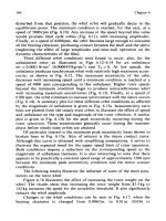
The
wall thickness
can
be
calculated
from
Chapter
12
and
a
value
of bed
height deter-
mined.
However, since
t
c
and e are
arbitrary,
a
10-ft
bed
seems
appropriate.
5.
Calculate
volume
of
iron sponge
to
purchase:
Example
No.
7-2:
Specify
Major
Parameters
for
DEA
Required:
1.
Show that
a DEA
unit
is an
acceptable process selection.
2.
Determine
DEA
circulation rate using
35 wt. % DEA and an
acid-
gas
loading
of
0.50
mole acid gas/mole DEA.
3.
Determine preliminary diameter
and
height
for DEA
contact tower.
4.
Calculate approximate reboiler
duty
with 250°F reboiler temperature.
Acid
Gas
Treating
193
Solution;
1.
Process selection
Total
acid
gas
inlet
=
4.03
+
0.0019
=
4.032%
Pacidin
=
1.015
x
(4.032/100)
=
40.9
psia
Total
acid
gas
outlet
=
2.0%
Pa«d.
out
=
1,015
x
(2.0/100)
=
20.3
psia
From Figure
7-12
for
removing
CO
2
and
H
2
S,
possible processes
are
amines,
Sulfinol,
or
carbonates.
The
most common selection
for
this application
is a DEA
unit.
2.
DEA
circulation
rate
Note:
In
order
to
meet
the
H
2
S
outlet,
virtually
all the
CO
2
must
be
removed,
as DEA is not
selective
for
H
2
S.
3.
Tower size
From Volume
1:
194
Design
of
GAS-HANDLING
Systems
and
Facilities
Use
72-in.
ID
tower w/24 trays,
4.
Determine reboiler duty:
Using
1,000
Btu/gal
lean
solution
q=l,000(508)(60
min/hr)
q
=
30.5
MMBtu/hr
CHAPTER
8
Gas
Dehydration
*
Gas
dehydration
is the
process
of
removing water vapor
from
a gas
stream
to
lower
the
temperature
at
which water will
condense
from
the
stream. This temperature
is
called
the
"dew
point"
of the
gas.
Most
gas
sales contracts specify
a
maximum value
for the
amount
of
water vapor
allowable
in the
gas.
Typical values
are 7
Ib/MMscf
in the
Southern
U.S.,
4
Ib/MMscf
in the
Northern
U.S.
and 2 to 4
Ib/MMscf
in
Canada. These
values
correspond
to dew
points
of
approximately
32°F
for 7
lb/
MMscf,
20°F
for 4 lb
MMscf,
and 0°F for 2
Ib/MMscf
in a
1,000
psi gas
line.
Dehydration
to dew
points below
the
temperature
to
which
the gas
will
be
subjected will prevent hydrate formation
and
corrosion
from
con-
densed water.
The
latter consideration
is
especially important
in gas
streams containing
CO
2
or
H
2
S
where
the
acid
gas
components
will
form
an
acid with
the
condensed water.
The
capacity
of a gas
stream
for
holding water vapor
is
reduced
as the
stream
is
compressed
or
cooled. Thus, water
can be
removed
from
the
gas
stream
by
compressing
or
cooling
the
stream. However,
the gas
stream
is
still saturated with water
so
that
further
reduction
in
tempera-
ture
or
increase
in
pressure
can
result
in
water condensation.
This chapter discusses
the
design
of
liquid glycol
and
solid
bed
dehy-
dration
systems that
are the
most common methods
of
dehydration used
*Reviewed
for the
1999
edition
by
Lindsey
S.
Stinson
of
Paragon
Engineering
Services,
Inc.
195
196
Design
of
GAS-HANDLING
Systems
and
Facilities
for
natural
gas.
In
producing operations
gas is
most
often
dehydrated
by
contact
with
triethylene
glycol. Solid
bed
adsorption units
are
used
wheie
very
low dew
points
are
required,
such
as on the
inlet stream
to a
crvo-
genic
gas
plant
where water contents
of
less
than
0.05
Ib/MMscf
may
bt
neiessat)
WATER
CONTENT DETERMINATION
The
first
step
in
evaluating
and/or
designing
a gas
dehydration system
is
to
determine
the
water content
of the
gas.
The
water content
of a gas is
dependent
upon
gas
composition, temperature,
and
pressure.
For
sweet
natural
gases
containing
over
70%
methane
and
small amounts
of
"heavy
ends,"
the
McKetta-Wehe pressure-temperature correlation,
as
shown
in
Figure
8-1,
may be
used.
As an
example, assume
it is
desired
to
deter-
mine
the
water content
for a
natural
gas
with
a
molecular
weight
of 26
that
is in
equilibrium with
a 3%
brine
at a
pressure
of
3,000
psia
and a
temperature
of
150°R
From Figure
8-1 at a
temperature
of
150°F
and
pressure
of
3,000
psia there
is 104
Ib
of
water
per
MMscf
of wet
gas.
The
correction
for
salinity
is
0.93
and for
molecular weight
is
0.98.
There-
fore,
the
total water content
is 104 x
0.93
x
0.98
=
94.8
Ib/MMscf.
A
correction
for
acid
gas
should
be
made when
the gas
stream contains
more
than
5%
CO
2
and/or
H
2
S.
Figures
8-2 and 8-3 may be
used
to
determine
the
water
content
of a gas
containing less than
40%
total
con-
centration
of
acid
gas.
As an
example, assume
the
example
gas
from
the
previous
paragraph contains
15%
H
2
S.
The
water content
of the
hydro-
carbon
gas is
94.8
Ib/MMscf.
From
Figure
8-3,
the
water
content
of
H
2
S
is
400
Ib/MMscf.
The
effective water content
of the
stream
is
equal
to
(0.85X94.8)+
(0.15)(400)
or 141
Ib/MMscf.
GLYCOL
DEHYDRATION
By
far the
most common process
for
dehydrating natural
gas is to
con-
tact
the gas
with
a
hygroscopic liquid such
as one of the
glycois. This
is
an
absorption process, where
the
water vapor
in the gas
stream becomes
dissolved
in a
relatively pure glycol liquid solvent stream. Glycol dehy-
dration
is
relatively inexpensive,
as the
water
can be
easily
"boiled"
out
of
the
glycol
by the
addition
of
heat. This step
is
called
"regeneration"
or
"reconcentration"
and
enables
the
glycol
to be
recovered
for
reuse
in
absorbing
additional water with minimal loss
of
glycol.
Gas
Dehydration
197
Water
Content
of
Hydrocarbon
Gas
Figure
8-1.
McKetta-Wehe
pressure-temperature correlation.
(From
Gas
Processors
Suppliers
Association,
Engineering
Data
Book,
10th
Edition.)
198
Design
of
GAS-HANDLING
Systems
and
Facilities
Figure 8*2.
Effective
water
content
of
CO
2
.
(From
Gas
Processors
Suppliers
Association,
engineering
Data
Book,
10th
Edition.)
Process
Description
Most
glycol
dehydration processes
are
continuous. That
is, gas and
glycol flow continuously through
a
vessel
(the
"contactor"
or
"absorber")
where they come
in
contact
and the
glycol absorbs
the
water.
The
glycol
flows
from
the
contactor
to a
"reboiler"
(sometimes
called
"reconcentrator"
or
"regenerator"
1
)
where
the
water
is
removed
or
"stripped"
from the
glycol
and is
then
pumped back
to the
contactor
to
complete
the
cycle.
Figure
8-4
shows
a
typical trayed contactor
in
which
the gas and
liquid
are in
counter-current
flow. The wet gas
enters
the
bottom
of the
contac-
tor
and
contacts
the
"richest"
glycol
(glycol containing water
in
solution)
Gas
Dehydration
199
Figure
8-3.
Effective
water
content
of
H
2
S.
(From
Gas
Processors
Suppliers
Association,
Engineering Data
Book,
I
Oth
Edition.)
just before
the
glycol leaves
the
column.
The gas
encounters
leaner
and
leaner glycol (that
is,
giycol containing
less
and
less
water
in
solution),
as
it rises
through
the
contactor.
At
each successive tray
the
leaner glycol
is
able
to
absorb additional amounts
of
water vapor
from
the
gas.
The
counter-current flow
in the
contactor makes
it
possible
for the gas to
transfer
a
significant amount
of
water
to the
glycol
and
still approach
equilibrium
with
the
leanest glycol concentration.
The
contactor works
in the
same manner
as a
condensate stabilizer
tower
described
in
Chapter
6. As the
glycol falls
from
tray
to
tray
it
becomes
richer and richer in
water.
As the gas rises it
becomes leaner
and
leaner
in
water vapor. Glycol contactors will typically have between
6
and
12
trays, depending upon
the
water
dew
point required.
To
obtain
a 7
Ib/MMscf
specification,
6 to 8
trays
are
common.
200
Design
of
GAS-HANDLING
Systems
and
Facilities
Figure
8-4.
Typical
glycol
contactor
in
which
gas and
liquid
are in
counter-current
flow.
As
with
a
condensate stabilizer, glycol contactors
may
have bubble
cap
trays
as
shown
in
Figure
8-4,
or
they
may
have valve trays, perforat-
ed
trays, regular packing
or
structured packing. Contactors that
are 12%
in. and
less
in
diameter usually
use
regular packing, while larger contac-
tors usually
use
bubble
cap
trays
to
provide adequate contact
at gas flow
rates much lower than design. Structured packing
is
becoming more
common
for
very large contactors.
It
is
possible
to
inject glycol
in a gas
line
and
have
it
absorb
the
water
vapor
in
co-current
flow.
Such
a
process
is not as
efficient
as
countercur-
rent
flow,
since
the
best that
can
occur
is
that
the gas
reaches near equi-
librium
with
the
rich glycol
as
opposed
to
reaching near equilibrium
with
Gas
Dehydration
201
the
lean
glycol
as
occurs
in
counter-current
flow.
Partial co-current
flow
can
be
used
to
reduce
the
height
of the
glycol contactor
by
eliminating
the
need
for
some
of the
bottom trays.
The
glycol
will
absorb heavy hydrocarbon liquids present
in the gas
stream.
Thus, before
the gas
enters
the
contactor
il
should pass
through
a
separate
inlet
gas
scrubber
to
remove
liquid
and
solid
impurities
that
may
carry
over
from
upstream vessels
or
condense
in
lines leading
from
ihe
vessels.
The
inlet scrubber
should
be
located
as
close
as
possible
to
the
contactor,
On
larger streams filter
separators
(Volume
1,
Chapter
4) are
used
as
inlet
scrubbers
to
further
reduce
glyco!
contamination
and
thus
increase
the
life
of the
glycol charge.
Due to
their cost,
filter
separators
are not
normally
used
on
streams less than approximately
50
MMscfd.
Often
on
these
smaller
units
a
section
in the
bottom
of the
contactor
is
used
as a
vertical
inlet
scrubber
as
shown
in
Figure
8-5.
Dry
gas
from
the top of the
gas/glycol
contactor
flows
through
an
external
gas/glycol heat exchanger. This cools
the
incoming
dry
glycol
to
increase
its
absorption capacity
and
decrease
its
tendency
to
flash
in the
contactor
and be
lost
to the dry
gas.
In
some
systems,
the gas
passes
over
a
glycol cooling coil
inside
the
contactor instead
of the
external
gas/gly-
col
heat exchanger.
The
glycol reconcentration system
is
shown
in
Figure
8-6.
The
rich
or
"wet"
glycol
from
the
base
of the
contactor passes through
a
reflux
con-
denser
to the
glycol/glycol
preheater
where
the rich
glycol
is
heated
by the
hot
lean
glycol
to
approximately 170°F
to
200°F.
After
heating,
the
glycol
flows
to a low
pressure separator operating
at 35 to 50
psig, where
the
entrained
gas and any
liquid hydrocarbons present
are
removed.
The
gly-
col/condensate
separator
is a
standard three-phase vessel designed
for at
least
15-30
minutes retention time
and may be
either horizontal
or
vertical.
It
is
important
to
heat
the
glycol before flowing
to
this
vessel
to
reduce
its
viscosity
and
encourage easier separation
of
condensate
and
gas.
The gas
from
the
glycol/condensate
separator
can be
used
for
fuel
gas,
In
many small
field
gas
packaged units this
gas is
routed directly
to
fire
lubes
in the
reboiler,
and
provides
the
heat
for
reconcentrating
the
glycol.
This
separator
is
sometimes referred
to as a
gas/glycol separator
or
"pump
gits"
separator.
The
wel
glycol from
the
separator
flows
through
a
sock
filter
to
remove solids
and a
charcoal
filter
to
absorb small amounts
of
hydrocar-
bons
that
may
build
up in the
circulating
glycol.
Sock filters
are
normally
designed
for the
removal
of
5-micron
solids.
On
units
larger than
10
gpm
202
Design
of
GAS-HAN
DUNG
Systems
and
Facilities
Figure
8-5.
The
bottom
of the
contactor
is
often used
as a
vertical
inlet
scrubber.
it
is
common
to
route only
a
sidestream
of 10 to 50% of
total
glycol
flow
through
the
charcoal filter.
The
filters help minimize foaming
and
sludge
build-up
in the
reconcentrator.
The
glycol then
flows
through
the
glycol/glycol
heat exchanger
to the
still
column mounted
on the
reconcentrator, which operates
at
essentially
atmospheric
pressure.
As the
glycol
falls
through
the
packing
in the
still
column,
it is
heated
by the
vapors being boiled
off the
liquids
in the
reboiler.
The
still
works
in the
same manner
as a
condensate stabilizer.
The
falling liquid gets hotter
and
hotter.
The gas flashing
from
this liquid
is
mostly water vapor with
a
small amount
of
glycol. Thus,
as the
liquid
falls
through
the
packing
it
becomes leaner
and
leaner
in
water. Before
the
vapors leave
the
still, they encounter
the
reflux condenser.
The
cold
rich glycol
from
the
contactor cools them, condensing
the
glycoi vapors
and
approximately
25 to 50% of the rising
water vapor.
The
result
is a
Gas
Dehydration
203
Figure
8-6.
Glycol
reconcentration
system.
reflux
liquid stream, which reduces
the
glycol
losses
to
atmosphere
to
almost zero.
The
water vapor exiting
the top of the
still contains
a
small
amount
of
volatile hydrocarbons
and is
normally vented
to
atmosphere
at
a
safe
location.
If
necessary,
the
water vapor
can be
condensed
in an
aeri-
al
cooler
and
routed
to the
produced water treating system
to
eliminate
any
potential atmospheric hydrocarbon emission.
Since there
is a
large difference between
the
boiling
point
of
triethyl-
ene
glycol
(546°F)
and
water
(212°F),
the
still column
can be
relatively
short
(10
to
12
ft of
packing).
The
glycol liquid
in the
reboiler
is
heated
to
340°F
to
400°F
to
provide
the
heat necessary
for the
still
column
to
operate.
Higher temperatures would vaporize more water,
but may
degrade
the
glycol.
If
a
very lean glycol
is
required,
it may be
necessary
to use
stripping
gas.
A
small amount
of wet
natural
gas can be
taken
from
the
fuel
stream
or
contactor inlet stream
and
injected into
the
reboiler.
The
stripping
gas
can
be
taken
from
the
fuel
stream
or the
contactor inlet stream
and
inject-
ed
into
the
reboiler.
The
"leaness"
of the gas
depends
on the
purity
of the
wet
glycol
and the
number
of
stages
below
the
reconcentrator.
The
strip-
ping
gas is
saturated with water
at the
inlet temperature
and
pressure con-
ditions,
but
adsorbs water
at the
reboiler conditions
of
atmospheric pres-
204
Design
of
GAS-HANDLING
Systems
and
Facilities
sure
and
high temperatures.
The gas
will
adsorb
the
waler
from
the
gly-
col by
lowering
the
partial pressure
of the
water vapor
in the
reboiler.
Stripping
gas
exits
in the
still column with
the
water vapor.
If
necessary.
I
he gas can be
recovered
by
condensing
the
water
and
routing
the
gas
to a
vapor
recovery compressor.
The
lean glycol
flows
from
the
reboiler
to a
surge tank which
could
be
constructed
as an
integral part
of the
reboiler
as in
Figure
8-6.
The
surge
tank
must
be
large enough
to
allow
for
thermal expansion
of the
glycol
and to
allow
for
reasonable time between additions
of
glycol.
A
well
designed
and
operated unit
will
have glycol losses
to the dry gas
from
the
contactor
and the
water vapor
from
the
still
of
between
0.01
and
0,05
gal/MMscf
of gas
processed.
The
lean glycol
from
the
atmospheric surge tank
is
then
pumped
back
to
the
contactor
to
complete
the
cycle.
Depending upon
the
pump design,
the
lean glycol
must
be
cooled
by the
heat exchangers
to
less
than
200
U
F
to
25()
C
F
before reaching
the
pumps. There
are
many variations
to the
basic
glycol
process
described above.
For
higher
"wet"
gas
flow
rates
greater
than
500
MMscfd,
the
"cold
finger"
condenser
process
as
shown
in
Figure
8-7 is
often
attractive.
A
cold finger condenser
tube
bundle
with
cold
rich
gas
from
the
contactor
is
inserted either into
the
vapor
space
at
the
reboiler
or
into
a
separate separator. This creates
a
"cold
finger" in
the
vapor space.
The
hydrocarbon liquid
and
vapor phases along
with
the
glycol/water
phase
are
separated
in a
three-phase separator.
The
lean gly-
col
from the
bottom
of the
condenser
is
cooled, pumped, cooled
again,
and fed to the
contactor.
Choice
of
Glycol
The
commonly available
glycols
and
their uses
are:
1.
Ethylene
glycol—High
vapor equilibrium with
gas so
tend
to
lose
to
gas
phase
in
contactor.
Use as
hydrate inhibitor where
it can be
recovered from
gas by
separation
at
temperatures below
50°
F.
2.
Diethylene
glycol—High
vapor pressure
leads
to
high losses
in
con-
tactor.
Low
decomposition temperature requires
low
reconcentrator
temperature
(315°F
to
340°F)
and
thus cannot
get
pure enough
for
most applications.
3.
Triethylene
glycol—Most
common. Reconcentrate
at
340°F
to
4()0°F
for
high purity.
At
contactor temperatures
in
excess
of
120°F
tends
to
have high vapor
losses
to
gas.
Dew
point depressions
up to
150°F
are
possible
with
stripping gas.
Gas
Dehydration
205
Figure
8*7.
Cold
finger
condenser
process.
4.
Tetraethylene
glycol—More
expensive than
triethylene
but
less
losses
at
high
gas
contact
temperatures. Reconcentrate
at
400°F
to
430°F.
Almost
all
field
gas
dehydration units
use
triethylene glycol
for the
reasons indicated. Normally when field
personnel
refer
to
"glycol"
they
mean
triethylene glycol
and
we
will
use
that
convention
in the
remainder
of
this
chapter.
Design
Considerations
Inlet
Gas
Temperature
At
constant pressure,
the
water content
of the
inlet
gas
increases
as the
inlet
gas
temperature increases.
For
example,
at
1,000 psia
and
80°F
gas
holds about
34
Ib/MMscf,
while
at
1,000 psia
and
120°F
it
will hold
about
104
Ib/MMscf.
At the
higher temperature,
the
glycol will have
to
206
Design
of
GAS-HANDLING
Systems
and
Facilities
remove
over three times
as
much
water
to
meet
a
pipeline
specification
of
7
lb/MMscf.
An
increase
in
gas
temperature
may
result
in an
increase
in the
required
diameter
of the
contact tower.
As was
shown
in
separator si/ing
(Volume
1,
Chapter
4), an
increase
in
temperature increases
the
actual
gas
velocity, which
in
turn increases
the
diameter
of the
vessel.
inlet
gas
temperatures above
120°F
result
in
high
triethylene
glycol
losses.
At
higher
gas
temperatures
tetraethylene
glycol
can be
used,
but
it
is
more common
to
cool
the gas
below 120°F before entering
the
contac-
tor.
The
more
the gas is
cooled, while staying above
the
hydrate
forma-
tion
temperature,
the
smaller
the
glycol
unit
required.
The
minimum inlet
gas
temperature
is
normally above
the
hydrate for-
mation
temperature
and
should always
be
above
50°F.
Below
50°F
gly-
col
becomes
too
viscous. Below 60°F
to
70°F glycol
can
form
a
stable
emulsion
with liquid hydrocarbons
in the gas and
cause
foaming
in
the
contactor.
There
is an
economic trade-off between
the
heat exchanger system
used
to
cool
the gas and the
size
of the
glycol unit.
A
larger
cooler
pro-
vides
for a
smaller glycol unit,
and
vice versa. Typically, triethylene gly-
col.
units
are
designed
to
operate with
inlet
gas
temperatures between
80°F
and
110°F.
Contactor Pressure
Contactor pressures have
little
effect
on the
glycol absorption
process
as
long
as the
pressures
remain
below
3,000
psig.
At a
constant tempera-
ture
the
water content
of the
inlet
gas
decreases
with increasing pressure,
thus
less water must
be
removed
if the gas is
dehydrated
at a
higher pres-
sure.
In
addition,
a
smaller contactor
can be
used
at
high pressure
as
the
actual
velocity
of the gas is
lower, which decreases
the
required diameter
of
the
contactor.
At
lower pressure less wall thickness
is
required
to
contain
the
pres-
sure
in a
given
diameter
contactor,
therefore,
an
economic
trade-off
exists
between
operating presssure
and
contactor cost.
Typically,
dehy-
dration
pressures
of 500 to
1,200
psi are
most
economical.
Number
of
Contactor
Trays
The
glycol
and the gas do not
reach equilibrium
on
each tray.
A
tray
efficiency
of 25% is
commonly used
for
design. That
is, if one
theoretical
Gas
Dehydration
207
equilibrium
tray
is
needed,
four
actual trays
are
specified.
In
bubble
cap
towers, tray spacing
is
normally
24 in.
The
more trays
the
greater
the
dew-point
depression
for a
constant
gly-
col
circulation
rate
and
lean glycol concentration.
By
specifying more
trays,
fuel
savings
can be
realized because
the
heat duty
of the
reboiler
is
directly
related
to the
glycol circulation rate. Figure
8-8
shows
how the
number
of
trays
can
have
a
much greater
effect
on
dew-point
depression
than
the
circulation rate.
The
additional investment
for a
taller contactor
is
often easily
justified
by
the
resultant
fuel
savings. Most contactors designed
for 1
Ib/MMscf
gas
are
sized
for 6 to 8
trays.
Lean
Giycol
Temperatures
The
temperature
of the
lean
glycol
entering
the
contactor
has an
effect
on
the
gas
dew-point
depression
and
should
be
held
low to
minimize
required circulation
rate.
High
glycol
losses
to the gas
exiting
the
contac-
Figure
8-8.
The
number
of
trays
can
have
a
greater
effect
on
dew-point
depression
than
the
circulation
rate.
208
Design
of
GAS-HANDLING
Systems
and
Facilities
tor may
occur when
the
lean glycol temperature gets
too
hot.
On the
other hand,
the
lean glycol temperature should
be
kept slightly above
the
contactor
gas
temperature
to
prevent hydrocarbon condensation
in the
contactor
and
subsequent foaming
of the
glycol. Most designs call
for a
lean
glycol temperature 10°F hotter than
the gas
exiting
the
contactor.
Glycol
Concentration
The
higher
the
concentration
of the
lean glycol
the
greater
the
dew-
point
depression
for a
given glycol circulation rate
and
number
of
trays,
Figure
8-9
shows
the
equilibrium water
dew
point
at
different
temper-
atures
for
gases
in
contact with various concentrations
of
glycoJ.
At
100°F
contact temperature there
is an
equilibrium water
dew
point
of
25°F
for 98%
glycol
and
10°F
for 99%
glycol. Actual
dew
points
of gas
leaving
the
contactor will
be
10°F
to
20°F higher than equilibrium.
Figure
8-10
shows that increasing
the
lean glycol concentration
can
have
a
much greater
effect
on
dew-point depression than increasing
the
circulation
rate.
To
obtain
a
70°F dew-point depression
a
circulation
rate
Figure
8-9.
Equilibrium
water
dew
points
at
different
temperatures
for
gases.
Gas
Dehydration
209
Figure
840.
increasing
gr/eof
concentration
has a
greater
effect
on
dew-point
depression
than
increasing
the
circulation
rate.
of
6.2
gaVlb
at
99.95%,
8.2
gal/lb
at
99.5%
or in
excess
of
12
gal/lb
at
99% is
required.
The
lean
glycol
concentration
is
determined
by the
temperature
of the
reboiler.
the gas
stripping rate,
and the
pressure
of the
reboiler. Glycol
concentrations
between
98 and
99%
are
common
for
most
field
gas
units.
Glycol
Reboiler
Temperature
The
reboiler temperature controls
the
concentration
of the
water
in the
lean
glycol.
The
higher
the
temperature
the
higher
the
concentration,
as
shown
in
Figure
8-11.
Reboiler
temperatures
for
triethylene
glycol
are
lim-
ited
to
400°F,
which limits
the
maximum lean glycol concentration
without
stripping
gas.
It is
good practice
to
limit reboiler temperatures
to
between
370°F
and
390°F
to
minimize degradation
of the
glycol. This
effectively
limits
the
lean glycol concentration
to
between 98.5%
and
98.9%.
210
Design
of
GAS-HANDLING
Systems
and
Facilities
Figure
8-11.
The
higher
the
temperature
the
greater
the
lean
glycol
concentration,
When higher lean glycol concentrations
are
required, stripping
gas can
be
added
to the
reboiler,
or the
reboiler
and
still column
can be
operated
at
a
vacuum,
Reboiler
Pressure
Pressures above atmospheric
in the
reboiler
can
significantly reduce
lean
glycol concentration
and
dehydration
efficiency.
The
still column
should
be
adequately vented
and the
packing replaced periodically
to
prevent
excess back pressure
on the
reboiler.
At
pressures below atmospheric
the
boiling temperature
of the
rich
glycol/water
mixture
decreases,
and a
greater lean glycol concentration
is
possible
at the
same reboiler temperature. Reboilers
are
rarely operated
at
a
vacuum
in field gas
installations, because
of the
added complexity
and
the
fact
that
any air
leaks will result
in
glycol
degradation.
In
addi-
tion,
it is
normally less expensive
to use
stripping
gas.
However,
if
lean
glycol concentrations
in the
range
of
99.5%
are
required, consider using
a
reboiler pressure
of 500 mm
Hg
absolute (approximately
10
psia)
as