ARNOLD, K. (1999). Design of Gas-Handling Systems and Facilities (2nd ed.) Episode 1 Part 10 pdf
Bạn đang xem bản rút gọn của tài liệu. Xem và tải ngay bản đầy đủ của tài liệu tại đây (1.5 MB, 25 trang )
Gas
Dehydration
211
well
as
using stripping
gas.
Sometimes
the
addition
of a
vacuum
will
help
extend
the
range
of an
existing glycol system.
Figure
8-11
can be
used
to
estimate
the
effect
of
vacuum
on
lean
gly-
col.
concentration,
Stripping
Gas
The
lean glycol concentration leaving
the
reboiler
can be
lowered
by
contacting
the
glycol
with
stripping
gas.
Often,
wet gas
that
is
saturated
with
water vapor
at
ambient temperature
and 25 to 100
psig
is
used.
At
25
psig
and
100°F
this
gas is
saturated with
1,500
Ib/MMscf
of
water
vapor.
At
atmospheric pressure
and the
temperatures
in the
reboiler
the
gas
can
absorb over
100,000
Ib/MMscf.
In
most situations
the
additional
fuel
gas
required
to
heat
the
reboiler
to
increase lean glycol concentration
is
less than
the
stripping
gas
required
for the
same
effect.
Thus,
it is
normally desirable
to use
strip-
ping
gas
only
to
increase lean glycol concentration above
98.5
to
98.9%,
which
can be
reached with normal reboiler temperatures
and
normal back
pressure
on the
still column.
If the
glycol circulation
rate
must
be
increased above design
on an
existing unit
and the
reboiler
cannot reach
desired
temperature,
it is
often
possible
to use
stripping
gas to
achieve
the
desired lean glycol concentration.
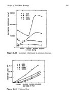
Figure
8-12
shows
the
effects
on the
glycol purity
of
stripping
gas
flow
rate
for
various
reboiler
temperatures, assuming
the gas is
injected
directly
into
the
reboiler.
Greater
purities
are
possible
if
stripping
gas
contacts
the
lean glycol
in a
column containing
one or
more
stages
of
packing
before entering
the
reboiler.
Glycol
Circulation Rate
When
the
number
of
absorber trays
and
lean glycol concentration
are
fixed,
the
dew-point depression
of a
saturated
gas is a
function
of the
gly-
col
circulation rate.
The
more glycol that comes
in
contact with
the
gas,
the
more water vapor
is
stripped
out of the
gas.
Whereas
the
glycol
con-
centration mainly
affects
the dew
point
of the dry
gas,
the
glycol rate
controls
the
total amount
of
water that
can be
removed.
The
minimum
circulation
rate
to
assure good
glycol-gas
contact
is
about
two
gallons
of
glycol
for
each pound
of
water
to be
removed. Seven gallons
of
glycol
per
pound
of
water removed
is
about
the
maximum rate. Most
standard
212
Design
of
GAS-HANDLING
Systems
and
Facilities
Figure
8-12.
Effect
of
stripping
gas on
glyco!
concentration.
dehydrators
are
designed
for
approximately three gallons
of
glycol
per
pound
of
water removed.
An
excessive circulation rate
may
overload
the
reboiler
and
prevent
good glycol regeneration.
The
heat required
by the
reboiler
is
directly
proportional
to the
circulation rate. Thus,
an
increase
in
circulation rate
may
decrease
reboiler
temperature, decreasing lean glycol concentration,
and
actually decrease
the
amount
of
water that
is
removed
by the
glycol
from
the
gas.
Only
if the
reboiler temperature remains constant will
an
increase
in
circulation rate lower
the dew
point
of the
gas.
Stripping
Still
Temperature
A
higher temperature
in the top of the
still column
can
increase glycol
losses
due to
excessive vaporization.
The
boiling point
of
water
is
212°F
and
the
boiling point
of TEG is
546°R
The
recommended temperature
in
the
top of the
still
column
is
approximately
225°F.
When
the
temperature
exceeds
250°F
the
glycol vaporization
losses
may
become
substantial.
The
still
top
temperature
can be
lowered
by
increasing
the
amount
of
gly-
col
flowing through
the
reflux
coil.
If
the
temperature
in the top of the
still column gets
too
low,
too
much
water
can be
condensed
and
increase
the
reboiler heat load.
Too
much
Gas
Dehydration
213
cool
glycoi circulation
in the
reflux
coil
can
sometimes lower
the
still
top
temperature below
220°F.
Thus, most reflux
coils
have
a
bypass
to
allow
manual
or
automatic control
of the
stripping still temperature.
Stripping
gas
will
have
the
effect
of
requiring reduced
top
still temper-
ature
to
produce
the
same
reflux
rate.
System
Sizing
Glycoi system sizing involves specifying
the
correct contactor diame-
ter
and
number
of
trays, which
establishes
its
overall
height;
selecting
a
glycol
circulation rate
and
lean glycoi concentration;
and
calculating
the
reboiler heat duty.
As
previously explained,
the
number
of
trays, glycoi
circulation
rate
and
lean glycol concentration
are all
interrelated.
For
example,
the
greater
the
number
of
trays
the
lower
the
circulation rate
or
lean
glycol concentration required. Figures
8-13,
8-16,
and
8-17
can be
used
to
relate
these three parameters.
Figure
8-13.
Glycoi concentration
vs.
glycoi circulation when
n = 1
theoretical tray.
214
Design
of
GAS-HANDLING
Systems
and
Facilities
Figure
8-14.
Structured (matrix)
packing,
(from
Koch
Industries.)
Contactor
Sizing
Bubble
cap
contactors
are the
most
common.
The
minimum diameter
can be
determined using
the
equation derived
for gas
separation
in
verti-
cal
separators (Volume
1,
Chapter
4).
This
is:
Gas
Dehydration
215
Figure
8-15.
Various
types
of
packing.
(Courtesy:
McGraw-Hill
Book
Company.}
216
Design
of
GAS-HANDLING
Systems
and
Facilities
Figure
8-16.
Glycol
concentration
vs.
glycol circulation when
n
=
1.5
theoretical
trays.
where
d
=
column inside
diameter,
in.
d
m
=
drop size, micron
T =
contactor operating temperature,
°R
Q
g
=
design
gas
rate, MMscfd
P =
contactor operating presssure, psia
C
D
=
drag
coefficent
p
g
=
gas
density,
lb/ft
3
p
g
= 2.7
SP/TZ
(Volume
1,
Chapter
3)
p!
=
density
of
glycol,
lb/ft
3
Z =
compressibility factor
(Volume
1,
Chapter
3)
S =
specific gravity
of gas
relative
to air
Reasonable
choices
of
contactor diameter
are
obtained when
the
con-
tactor
is
sized
to
separate
120-150
micron droplets
of
glycol
in the
gas.
The
density
of
glycol
can be
estimated
as 70
lb/ft
3
.
The
diameter
of
packed towers
may
differ
depending upon parameters
developed
by the
packing manufacturers
and
random packing. Conven-
tional
packing
will
require approximately
the
same diameter
as
bubble
Gas
Dehydration
217
Figure
8-17.
Glycol concentration
vs.
glycol circulation when
n = 2
theoretical trays.
cap
towers. Structured packing
can
handle higher
gas flow
rates
than
bubble
cap
trays
in the
same diameter contactor.
(See
Table
8-1.)
Conventional
and
random packing
will
require approximately
the
same
diameter
as
bubble caps. Structured packing
can
handle higher
gas
flow
rates than bubble caps
in the
same diameter contactor while requiring half
the
height.
The
height
per
equivalent
theoretical
tray normally ranges
from
8 ft for low
dewpoints
to 4 ft for
moderate dewpoints. Adequate mist
eliminator
and
glycol distribution
is
needed
for
high
gas flow
rates.
Reboiler
Heat Duty
The
reboiler heat
duty
can be
calculated using
the
techniques
in
Chap-
ter
2, by
sizing
the
reflux
coil
and
heat exchangers
and
calculating
the
temperature
at
which
the wet
glycol enters
the
still.
The
reboiler duty
is
then
the sum of the
sensible
heat required
to
raise
the wet
glycol
to
reboil-
er
temperature,
the
heat required
to
vaporize
the
water
in the
glycol,
the
heat
required
for the
reflux
(which
is
estimated
at 25 to 50% of the
heat
required
to
vaporize
the
water
in the
glycol)
and
losses
to
atmosphere.
218
Design
of
GAS-HANDLING
Systems
and
Facilities
Table
8-1
Example
Contactor Sizes
for
Dehydrating
50
MMscfd
at
1,000
psig
and
100°F
Tower
Tower Diameter
Internals
(inch)
A.
Tray
Bubble
Cap
B.
Structural Packing (Figures 6-9,
B
1-300
B
1-100
Flexipac#l
Flexipac
#2
C.
Random Packing (Figure 8-15)
2"
Pall Ring
48
8-14)
36
30
42
30
48
Troy/Pocking
Height
ffeet)
16
8
8
6
8
16
In
sizing
the
various heat exchangers
it is
common
to
assume
a
10°F
loss
of rich
glycol temperature
in the
reflux
coil,
a
desired temperature
of
175°F
to
200°F
for the rich
glycol
after
the
preheater
and a rich
glycol
temperature
after
the
glycol/glycol
heat exchanger
of
275°F
to
300°F
It is
necessary
to
make sure that
the
lean glycol temperature
to the
pumps
does
not
exceed
200°F
for
glycol powered pumps
and
250°F
for
plunger
pumps.
The
temperature
of
lean glycol
after
the
glycol/gas
exhanger
should
be
approximately
10°F
above
the
temperature
of the gas in the
contactor.
The
water vapor boiled from
the
rich glycol plus
the
reflux
water vapor must
be
cooled
from
approximately 320°F
to
220°F
by the
reflux
coil.
Exchanger heat transfer factors,
"U,"
can be
approximated
as 10 to
12
Btu/hr-ft
2
-°F
for
glycol/glycol exchangers,
45
Btu/hr-ft
2
-°F
for the
gas/
glycol exchanger,
and 100
Btu/hr-ft
2
-°F
for the
reflux
coil.
The
specific
heat
of
triethylene
glycol
is
given
in
Figure
8-15.
Table
8-2 can be
used
for an
initial approximation
of
reboiler duties.
If
the
reboiler
is
heated with
a
fire
tube,
the fire
tube
should
be
sized
for a
maximum
flux
rate
of
8,000
Btu/hr-ft
2
.
Glycol
Powered
Pumps
The
process
flow
schematic
in
Figure
8-6
shows electric motor driven
glycol
pumps.
On
smaller systems
it is
common
to use
glycol powered
pumps.
These pumps
use the
energy contained
in the
rich (wet) glycol
to
Gas
Dehydration
219
Figure
8-18.
Specific
heat
of
triethylene
glycol.
(Courtesy
of
Union
Carbide,
Gas
Treating Chemicals.)
Table
8-2
Approximate
Reboiler Heat Duty
Design
Gallons
of
Glycol
Circulated
/Ib
H
2
O
Removed
2.0
2.5
3.0
3.5
4.0
4.5
5.0
5.5
6.0
Reboiler
Heat
Duty
Btu/Gal
of
Glycol
Circulated
1066
943
862
805
762
729
701
680
659
Size
at
150%
of
above
to
allow
for
start-up, increased
circulation,
fouling.
pump
the
lean (dry) glycol
to the
contactor.
The
action
of
this type pump
is
shown
in
Figures
8-19
and
8-20. With
the
main piston moving
to the
left
(Figure
8-19),
dry
glycol
is
drawn into
the
left
cylinder
and
dis-
charged
from
the one at the
right.
Wet
glycol
is
drawn into
the
right
cylinder
and
discharged
from
the
left
cylinder.
As the
piston completes
220
Design
of
GAS-HANDLING
Systems
and
Facilities
Figure
8-19.
Glycol-powered
pump—piston
moving
to
left.
(Source:
Kimroy,
Inc.)
its
movement
to the
left,
it
moves
the
"D"
slide
to the
position
shown
in
Figure
8-19.
This reverses
the
pilot
slide position, which reverses
the
action
of the
piston.
Even
though
the wet
glycol drops
in
pressure
from
contactor pressure
to
condensate/separator
pressure,
it has
enough energy
to
pump
the dry
glycol
from
atmospheric pressure
to
contactor pressure. This
is
because
it
contains
more water
and gas in
solution,
but
also because
gas
from
the
contactor
flows out
with
the wet
glycol. There
is no
level control
valve
on
the
contactor when using
a
glycol powered pump.
Sufficient
contactor
gas is
automatically drawn
into
the wet
glycol
line
to
power
the
pump
at
the
rate
set
by
the
speed control valves. This
gas,
as
well
as the
approxi-
mately
1
scf/gal
gas in
solution
in the
glycol,
is
separated
in the
conden-
Gas
Dehydration
221
Figure
8-20.
Glycol-powered
pump—piston
moving
to
right.
(Source:
Kimray,
Inc.)
sate separator giving
it an
alternative designation
as
"pump
gas
separa-
tor."
The
free
gas
consumption
of the
glyeol
pump
is
given
in
Table
8-3.
The
pump
gas can be
used
to
fuel
the
reboiler.
The
amount
of
pump
gas
is
normally close
to
balancing
the
reboiler
fuel
gas
requirements.
The
pump
gas can
also
be
routed
to the
facility
fuel
gas
system
or to a
low-
pressure
system
for
compression
and
sales.
If it is not
recovered
in one of
these
ways
and is
just vented locally,
the
cost
of
using this type
of
pump
can be
very high.
Glyeol powered pumps
are
inexpensive
and
easy
to
repair
in the field.
They have many moving parts
and
because
of
their slamming reciprocat-
ing
motion
require constant
attention.
One
spare pump
should
always
be
installed.
222
Design
of
GAS-HANDLING
Systems
and
Facilities
Table
8-3
Gas
Consumption
by
Glycol Powered Pump
Contactor
Operating
Pressure
psig
300
400
500
600
700
800
900
1000
1100
1200
1300
1400
1500
Pump
Gas
Consumption
sc
f/gal
1.7
2.3
2.8
3.4
3.9
4.5
5.0
5.6
6.1
6.7
7.2
7.9
8.3
EXAMPLE
8-1:
GLYCOL
DEHYDRATION
Problem:
1.
Calculate contactor diameter.
2.
Determine glycol circulation rate
and
estimate reboiler
duty.
3.
Calculate duties
for
gas/glycol
exchanger
and
glycol/glycol
ex-
changers.
Gas
Dehydration
223
Calculate
Contactor
Diameter
Use
72-in.
ID
contactor.
Determine
Glycol
Circulation
Rate
and
Reboiler
Duty
Wj
=
63
Ib/MMscf
W
0
= 7
Ib/MMscf
AW
= 63 - 7 = 56
Ib/MMscf
AW/Wj
=
56/63
=
.889
Assume
8
actual trays
or 2
theoretical trays. From Figure
8-17
the
gly-
col
circulation rate
is 2.8 gal
TEG/lb
H
2
0.
Size
for 3.0
gal/lb.
224
Design
of
GAS-HANDLING
Systems
and
Facilities
Estimate
reboiler duty:
Use
a 750
MBtu/hr
reboiler
to
allow
for
startup heat loads.
Calculate
Duties
of
Heat Exchangers
Rich
glycol composition
Rich
glycol
flow
rate
(W
rich
)
Rich glycol heat doty
(g^cb)
*
GtycoJ/glycol
exchanger
226
Design
of
GAS-HANDLING
Systems
and
Facilities
Rich
glycol
heat
duty
Lean
glycol
flow
rate
(W]
ean
)
Calculation
of
T
4
Gas
Dehydration
227
*
Glycol/glycol
preheater—calculate
lean
side
Temperature
*
Gas/glycol
exchanger
duty
228
Design
of
GAS-HANDLING
Systems
and
Facilities
It
is
possible
to
recover more heat
from
the
lean glycol
and
reduce
the
lean glycol temperature
to the
pumps
to
180°F
to
200°F
by
making
the
glycol/glycol
exchanger larger,
but
this
is not
required
in
this case. This
would
also increase
the
temperature
of the rich
glycol
flowing on the
still
to
more than
300°F
and
would decrease
the
reboiler heat
duty.
SOLID
BED
DEHYDRATION
Solid
bed
dehydration systems work
on the
principle
of
adsorption.
Adsorption involves
a
form
of
adhesion
between
the
surface
of the
solid
desiccant
and the
water vapor
in the
gas.
The
water forms
an
extremely
thin
film
that
is
held
to the
desiccant surface
by
forces
of
attraction,
but
there
is no
chemical reaction.
The
desiccant
is a
solid, granulated drying
or
dehydrating
medium
with
an
extremely large
effective
surface area
per
unit
weight
because
of a
multitude
of
microscopic pores
and
capillary
Gas
Dehydration
229
openings.
A
typical
desiccant
might
have
as
much
as 4
million
square
feet
of
surface area
per
pound.
The
initial cost
for a
solid
bed
dehydration unit generally exceeds
that
of
a
glycol
unit.
However,
the dry bed has the
advantage
of
producing
very
low dew
points, which
are
required
for
cryogenic
gas
plants (see
Chapter
9),
and is
adaptable
to
very large changes
in flow
rates.
A dry
bed
can
handle high contact temperatures. Disadvantages
are
that
it is a
batch
process, there
is a
relatively
high
pressure drop through
the
system,
and
the
desiccants
are
sensitive
to
poisoning
with
liquids
or
other
impuri-
ties
in the
gas.
Process
Description
Multiple
desiccant beds
are
used
in
cyclic operation
to dry the gas on a
continuous basis.
The
number
and
arrangement
of the
desiccant beds
may
vary
from
two
towers, adsorbing alternately,
to
many towers. Three
separate
functions
or
cycles must alternately
be
performed
in
each
deny-
drator.
They
are an
adsorbing
or gas
drying cycle,
a
heating
or
regenera-
tion
cycle,
and a
cooling cycle.
Figure
8-21
is a flow
diagram
for a
typical two-tower solid desiccant
dehydration
unit.
The
essential components
of any
solid desiccant dehy-
dration
system are:
1,
Inlet
gas
separator.
2,
Two or
more
adsorption towers (contactors)
filled
with
a
solid
des-
iccant,
3,
A
high-temperature
heater
to
provide
hot
regeneration
gas to
reacti-
vate
the
desiccant
in the
towers.
4,
A
regeneration
gas
cooler
to
condense water
from
the hot
regenera-
tion
gas.
5,
A
regeneration
gas
separator
to
remove
the
condensed water
from
the
regeneration gas.
6,
Piping, manifolds, switching valves
and
controls
to
direct
and
con-
trol
the
flow
of
gases
according
to the
process
requirements.
In
the
drying cycle,
the wet
inlet
gas
first
passes through
an
inlet sepa-
rator where
free
liquids, entrained mist,
and
solid particles
are
removed,
This
is a
very
important
part
of the
system because
free
liquids
can
dam-
age or
destroy
the
desiccant
bed and
solids
may
plug
it. If the
adsorption
230
Design
of
GAS-HANDLING
Systems
and
Facilities
Figure
8-21.
Simplified
flow
diagram
of a
solid
bed
dehydrator,
unit
is
downstream
from
an
amine
unit,
glycol
unit
or
compressors,
a
fil-
ter
separator
is
preferred.
In
the
adsorption cycle,
the wet
inlet
gas flows
downward through
the
tower.
The
adsorbable
components
are
adsorbed
at
rates dependent
on
their chemical nature,
the
size
of
their molecules,
and the
size
of the
pores.
The
water molecules
are
adsorbed
first
in the top
layers
of the
des-
iccant
bed.
Dry
hydrocarbon gases
are
adsorbed throughout
the
bed.
As
the
upper layers
of
desiccant become saturated with water,
the
water
in
the
wet gas
stream begins displacing
the
previously adsorbed hydrocar-
bons
in the
lower desiccant layers. Liquid hydrocarbons will
also
be
absorbed
and
will
fill
pore spaces
that
would otherwise
be
available
for
water
molecules.
For
each component
in the
inlet
gas
stream, there will
be a
section
of
bed
depth,
from
top to
bottom, where
the
desiccant
is
saturated with
that
component
and
where
the
desiccant below
is
just starting
to
adsorb
that
component.
The
depth
of bed
from
saturation
to
initial adsorption
is
known
as the
mass transfer zone. This
is
simply
a
zone
or
section
of the
bed
where
a
component
is
transferring
its
mass
from
the gas
stream
to
the
surface
of the
desiccant.
As
the
flow
of gas
continues,
the
mass transfer zones move downward
through
the bed and
water displaces
the
previously adsorbed gases
until
Gas
Dehydration
231
finally
the
entire
bed is
saturated with water vapor.
If the
entire
bed
becomes completely saturated
with
water vapor,
the
outlet
gas is
just
as
wet
as the
inlet
gas.
Obviously,
the
towers must
be
switched
from
the
adsorption
cycle
to the
regeneration cycle (heating
and
cooling) before
the
desiccant
bed is
completely saturated
with
water.
At
any
given time,
at
least
one of the
towers
will
be
adsorbing while
the
other towers will
be in the
process
of
being heated
or
cooled
to
regen-
erate
the
desiccant. When
a
tower
is
switched
to the
regeneration cycle
some
wet gas
(that
is, the
inlet
gas
downstream
of the
inlet
gas
separator)
is
heated
to
temperatures
of
450°F
to
600°F
in the
high-temperature
heater
and
routed
to the
tower
to
remove
the
previously
adsorbed
water.
As
the
temperature within
the
tower
is
increased,
the
water captured
within
the
pores
of the
desiccant
turns
to
steam
and is
absorbed
by the
natural
gas.
This
gas
leaves
the top of the
tower
and is
cooled
by the
regeneration
gas
cooler. When
the gas is
cooled
the
saturation
level
of
water
vapor
is
lowered significantly
and
water
is
condensed.
The
water
is
separated
in the
regeneration
gas
separator
and the
cool, saturated regen-
eration
gas is
recycled
to be
dehydrated. This
can be
done
by
operating
the
dehydration tower
at a
lower pressure
than
the
tower being regenerat-
ed or by
recompressing
the
regeneration gas.
Once
the bed has
been
"dried"
in
this manner,
it is
necessary
to
flow
cool
gas
through
the
tower
to
return
it to
normal operating temperatures
(about
100°F
to
120°F)
before placing
it
back
in
service
to
dehydrate gas.
The
cooling
gas
could either
be wet gas or gas
that
has
already been
dehydrated.
If wet gas is
used,
it
must
be
dehydrated after being used
as
cooling
gas.
A, hot
tower will
not
sufficiently
dehydrate
the
gas.
The
switching
of the
beds
is
controlled
by a
time
controller
that
per-
forms
switching
operations
at
specified times
in the
cycle.
The
length
of
the
different
phases
can
vary considerably.
Longer
cycle
times will
require larger
beds,
but
will increase
the bed
life.
A
typical
two-bed
cycle
might
have
an
eight-hour adsorption period with
six
hours
of
heating
and
two
hours
of
cooling
for
regeneration. Adsorption units
with
three beds
typically
have
one bed
being regenerated,
one
fresh
bed
adsorbing,
and
one bed in the
middle
of the
drying cycle.
Internal
or
external insulation
for the
adsorbers
may be
used.
The
main
purpose
of
internal
insulation
is to
reduce
the
total regeneration
gas
requirements
and
costs. Internal insulation eliminates
the
need
to
heat
and
cool
the
steel walls
of the
adsorber vessel.
Normally,
a
castable
re
factory
lining
is
used
for
internal
insulation.
The
refractory must
be
applied
and
properly cured
to
prevent liner cracks. Liner cracks
will
per-
232
Design
of
GAS-HANDLING
Systems
and
Facilities
mit
some
of the wet gas to
bypass
the
desiccant
bed.
Only
a
small
amount
of
wet,
bypassed
gas is
needed
to
cause
freezeups in
cryogenic
plants.
Ledges installed every
few
feet along
the
vessel
wall
can
help
eliminate
this problem.
Design
Considerations
Tempe
ratu
re
Adsorption
plant operation
is
very sensitive
to the
temperature
of the
incoming
gas.
Generally,
the
adsorption
efficiency
decreases
as the
tem-
perature
increases.
The
temperature
of the
regeneration
gas
that
commingles with
the
incoming
wet gas
ahead
of the
dehydrators
is
also important.
If the
tem-
perature
of
these
two gas
streams
differs
more than
15°F
to
20°F,
liquid
water
and
hydrocarbons will condense
as the
hotter
gas
stream cools.
The
condensed liquids
can
shorten
the
solid desiccant
life.
The
temperature
of the hot gas
entering
and
leaving
a
desiccant tower
during
the
heating cycle
affects
both
the
plant
efficiency
and the
desic-
cant life.
To
assure good removal
of the
water
and
other
contaminants
from
the
bed,
a
high regeneration
gas
temperature
is
needed.
The
maxi-
mum
hot gas
temperature
depends
on the
type
of
contaminants
and the
"holding power"
or
affinity
of the
dessicant
for the
contaminants,
A
tem-
perature
of
450°F
to
60G°F
is
normally
used.
The
desiccant
bed
temperature attained during
the
cooling cycle
is
important.
If wet gas is
used
to
cool
the
desiccant,
the
cooling cycle
should
be
terminated when
the
desiccant
bed
reaches
a
temperature
of
approximately
215°F.
Additional cooling
may
cause water
to be
adsorbed
from
the wet gas
stream
and
presaturate
or
preload
the
desiccant
bed
before
the
next adsorption cycle begins.
If dry gas is
used
for
cooling,
the
desiccant
bed
should
be
cooled within 10°F~20°F
of the
incoming
gas
temperature
during
the
adsorption cycle, thereby maximizing
the
adsorp-
tion capacity
of the
bed.
The
temperature
of the
regeneration
gas in the
regeneration
gas
scrub-
ber
should
be low
enough
to
condense
and
remove
the
water
and
hydro-
carbons
from
the
regeneration
gas
without causing hydrate problems.
Gas
Dehydration
233
Pressure
Generally,
the
adsorption capacity
of a dry bed
unit decreases
as the
pressure
is
lowered.
If the
dehydrators
are
operated well below
the
design
pressure,
the
desiccant
will have
to
work harder
to
remove
the
water
and
to
maintain
the
desired
effluent
dew
point.
With
the
same volume
of
incoming
gas,
the
increased
gas
velocity, occurring
at the
lower pressures,
could
also
affect
the
effluent
moisture
content
and
damage
the
desiccant,
Cycle Time
Most
adsorbers operate
on a
fixed
drying cycle time
and,
frequently,
the
cycle time
is set for
the
worst conditions. However,
the
adsorbent
capacity
is
not a
fixed value;
it
declines
with
usage.
For the
first
few
months
of
operation,
a new
desiccant
has a
very high capacity
for
water
removal.
If a
moisture analyzer
is
used
on the
effluent
gas,
a
much longer
initial
drying cycle
can
be
achieved.
As the
desiccant ages,
the
cycle time
will
be
automatically
shortened. This will save regeneration
fuel
costs
and
improve
the
desiccant
life.
Gas
Velocities
Generally,
as the gas
velocity during
the
drying cycle decreases,
the
ability
of the
desiccant
to
dehydrate
the gas
increases.
At
lower
actual
velocities, drier
effluent
gases
will
be
obtained. Consequently,
it
would
seem
desirable
to
operate
at
minimum velocities
to
fully
use the
desiccant.
However,
low
velocities require towers with large cross-sectional
areas
to
handle
a
given
gas flow, and
allow
the wet gas to
channel
through
the
desiccant
bed and not be
properly dehydrated.
In
selecting
the
design velocity therefore,
a
compromise
must
be
made between
the
tower diameter
and the
maximum
use of the
desiccant. Figure
8-22
shows
a
maximum design velocity. Smaller velocities
may be
required
due
to
pressure drop considerations.
The
minimum vessel internal diameter
for a
specified superficial
velocity
is
given
by:
234
Design
of
GAS-HANDLING
Systems
and
Facilities
Figure
8-22.
Maximum design velocity
for
solid
bed
adsorbers.
where
d =
vessel
internal
diameter,
in.
Bed
Height
to
Diameter
Ratio
In
its
simplest form,
an
adsorber
is
normally
a
cylindrical tower
filled
with
a
solid
desiccant.
The
depth
of the
desiccant
may
vary
from
a few
feet
to 30 ft or
more.
The
vessel diameter
may be
from
a few
inches
to 10
or
15
ft. A bed
height
to
diameter
(L/D)
ratio
of
higher than
2.5 is
desir-
able. Ratios
as low as 1:1 are
sometimes used; however, poor
gas
dehy-
dration,
caused
by
non-uniform
flow,
channeling
and an
inadequate
con-
tact
time between
the wet gas and the
desiccant sometimes result.
Gas
Dehydration
235
Pressure Drop
Towers
are
sized
for a
design pressure drop
of
about
5 psi
through
the
desiccant.
The
pressure drop
can be
estimated
by:
where
AP =
pressure drop,
psi
L =
length
of
bed,
ft
jj,
= gas
viscosity,
cp
p
= gas
density,
lb/ft
3
V
m
= gas
superficial velocity,
ft/min
B
and
C are
constants given
by:
Particle
Type
^-in.
bead
%-in.
extradate
Mfi-in.
bead
!4-in,
extradate
B
0.0560
0.0722
0.152
0.238
C
0.0000889
0.000124
0.000136
0.000210
Pressure drops
of
greater than approximately
8 psi are not
recommended.
Moisture
Content
of
Inlet
Gas
An
important variable that determines
the
size
of a
given desiccant
bed
is
the
relative saturation
of the
inlet
gas.
This variable
is the
driving force
that
affects
the
transfer
of
water
to the
adsorbent.
If
saturated
gas
(100%
relative humidity)
is
being
dried,
higher
useful
capacities
can be
expect-
ed for
most
desiccants
than when drying partially saturated gases.
How-
ever,
in
most
field
gas
dehydration installations
the
inlet
gas is
saturated
with
water vapor
and
this
is not a
variable
that
must
be
considered.
Desiccant
Selection
No
desiccant
is
perfect
or
best
for all
applications.
In
some applica-
tions
the
desiccant choice
is
determined primarily
by
economics. Some-
times
the
process conditions control
the
desiccant choice. Many times
the