ARNOLD, K. (1999). Design of Gas-Handling Systems and Facilities (2nd ed.) Episode 2 Part 7 docx
Bạn đang xem bản rút gọn của tài liệu. Xem và tải ngay bản đầy đủ của tài liệu tại đây (1.21 MB, 25 trang )
CHAPTIR
14
Safety
Systems*
This chapter discusses overall
safety
analysis techniques
for
evaluating
production facilities, describes
the
concepts used
to
determine where
safe-
ty
shutdown sensors
are
required,
and
provides background
and
insight
into
the
concept
of a
Safety
and
Environmental Management Program.
To
develop
a
safe
design,
it is
necessary
to first
design
and
specify
all
equipment
and
systems
in
accordance with applicable
codes
and
stan-
dards. Once
the
system
is
designed,
a
process safety shutdown system
is
specified
to
assure that potential hazards that
can be
detected
by
measur-
ing
process upsets
are
detected,
and
that appropriate safety actions (nor-
mally
an
automatic shutdown)
are
initiated.
A
hazards analysis
is
then
normally undertaken
to
identify
and
mitigate potential hazards that
could
lead
to fire,
explosion, pollution,
or
injury
to
personnel
and
that cannot
be
detected
as
process
upsets. Finally,
a
system
of
safety management
is
implemented
to
assure
the
system
is
operated
and
maintained
in a
safe
manner
by
personnel
who
have received adequate training.
Safety
analysis concepts
are
discussed
in
this chapter
by
first
describ-
ing
a
generalized hazard tree
for a
production facility. From this analysis,
decisions
can be
made regarding devices that could
be
installed
to
moni-
tor
process upset conditions
and to
keep them
from
creating hazards.
^Reviewed
for the
1999 edition
by
Benjamin
T.
Banken
of
Paragon Engineering
Services, Inc.
386
Safety
Systems
387
This
analysis forms
the
basis
of a
widely used industry consensus
stan-
dard,
American Petroleum Institute, Recommended Practice 14C, Analy-
sis, Design, Installation,
and
Testing
of
Basic
Surface
Systems
for
Off-
shore
Production
Platforms
(RP14C), which contains
a
procedure
for
determining
required process
safety
devices
and
shutdowns.
The
proce-
dures
described here
can be
used
to
develop checklists
for
devices
not
covered
by
RP14C
or to
modify
the
consensus checklists presented
in
RP14C
in
areas
of the
world where
RP14C
is not
mandated.
While
RP14C provides guidance
on the
need
for
process
safety
devices,
it is
desirable
to
perform
a
complete hazards analysis
of the
facility
to
identify
hazards that
are not
necessarily detected
or
contained
by
process
safety devices
and
that could lead
to
loss
of
containment
of
hydrocarbons
or
otherwise lead
to
fire, explosion,
pollution,
or
injury
to
personnel.
The
industry consensus standard, American Petroleum Insti-
tute
Recommended Practice 14J, Design
and
Hazards
Analysis
for
Off-
shore
Facilities (RP14J), provides guidance
as to the use of
various
haz-
ards analysis techniques.
The final
portion
of
this chapter
describes
the
management
of
safety
using
Safety
and
Environmental Management Programs
(SEMP)
as
defined
in API
RP75, Recommended Practices
for
Development
of a
Safety
and
Environmental Management Program
for the
Outer Continen-
tal
Shelf
(OCS)
Operations
and
Facilities,
and
using
a
Safety
Case
approach
as is
commonly done
in the
North Sea.
HAZARD
TREE
The
purpose
of a
hazard tree
is to
identify
potential hazards,
define
the
conditions
necessary
for
each hazard,
and
identify
the
source
for
each
condition. Thus,
a
chain
of
events
can be
established that forms
a
neces-
sary
series
of
required steps that results
in the
identified hazard. This
is
called
a
"hazard
tree."
If any of the
events leading
to the
hazard
can be
eliminated
with
absolute certainty,
the
hazard itself
can be
avoided.
A
hazard tree
is
constructed
by
first
identifying potential hazards.
Starting
with
the
hazard itself,
it is
possible
to
determine
the
conditions
necessary
for
this hazard
to
exist.
For
these conditions
to
exist,
a
source
that
creates that condition must exist
and so
forth.
Using this reasoning,
a
hierarchy
of
events
can be
drawn, which becomes
the
hazard tree.
In a
hazard analysis
an
attempt
is
made, starting
at the
lowest
level
in the
tree,
to
see if it is
possible
to
break
the
chain leading
to the
hazard
by
elimi-
388
Design
of
GAS-HANDLING
Systems
and
Facilities
nating
one of the
conditions. Since
no
condition
can be
eliminated
with
absolute
certainty,
an
attempt
is
made
to
minimize
the
occurrence
of
each
of
the
steps
in
each chain leading
to the
hazard
so
that
the
overall
proba-
bility
of the
hazard's occurrence
is
within acceptable limits.
This
process
is
perhaps best illustrated
by a
simple
example.
Figure
14-1
shows
a
hazard
tree
developed
for the
"hazard"
of
injury
while
walking
down
a
corridor
in an
office.
The
conditions leading
to
injury
are
identified
as
collision with others, tripping,
hit by
falling object,
and
total
building
failure.
The
sources leading
to
each condition
are
listed under
the
respective condition. Some
of the
sources
can be
further
resolved
into
activities
that could result
in the
source.
For
example,
if no
soil boring
was
taken this could lead
to
"inadequate
design,"
which would lead
to
''building
failure," which could lead
to
""injury."
It is
obvious that
it is
impossible
to be
absolutely certain that
the
hazard
tree
can be
broken.
It is,
however, possible
to set
standards
for
ceiling
design,
lighting, door construction, etc., that
will
result
in
acceptable
fre-
quencies
of
collision, tripping, etc.,
given
the
severity
of the
expected
injury
from the
condition. That
is, we
could conclude that
the
probability
of
building failure should
be
lower than
the
probability
of
tripping because
of
the
severity
of
injury
that
may be
associated
with
building failure.
Figure
14-1.
Hazard
tree
for
injury
suffered
white
walking
in a
hallway.
Safety
Systems
389
It
should
be
obvious from this discussion that
the
technique
of
creating
a
hazard tree
is
somewhat subjective. Different evaluators will
likely
classify
conditions
and
sources
differently
and may
carry
the
analysis
to
further
levels
of
sources. However,
the
conclusions reached concerning
building
design, maintenance, layout
of
traffic
patterns, lighting,
etc.,
should
be the
same.
The
purpose
of
developing
the
hazard
tree
is to
focus
attention
and
help
the
evaluator
identify
all
aspects that must
be
consid-
ered
in
reviewing
overall
levels
of
safety.
It
is
possible
to
construct
a
hazard tree
for a
generalized production
facility,
just
as it is
possible
to
construct
a
hazard tree
for a
generalized
hallway.
That
is,
Figure
14-1
is
valid
for a
hallway
in
Paragon Engineer-
ing
Services'
offices
in
Houston,
in
Buckingham
Palace
in
London,
or in
a
residence
in
Jakarta.
Similarly,
a
generalized hazard tree constructed
for a
production facility could
be
equally valid
for an
onshore
facility
or
an
offshore facility,
no
matter what
the
specific
geographic
location.
Figure
14-2
is a
hazard tree
for a
generalized production
facility.
The
hazards
are
identified
as
"oil pollution," "fire/explosion,"
and
"injury."
Beginning
with
injury,
we can see
that
the
hazards
of
fire/explosion
and
oil
pollution become conditions
for
injury
since they
can
lead
to
injury
as
well
as
being hazards
in
their
own
right.
The
tree
was
constructed
by
beginning
with
the
lowest level hazard,
oil
pollution.
Oil
pollution occurs
as
a
result
of an oil
spill
but
only
if
there
is
inadequate containment. That
is,
if
there
is
adequate
containment, there cannot
be oil
pollution.
Onshore, dikes
are
constructed around tank farms
for
this reason. Off-
shore, however,
and in
large onshore facilities
it is not
always possible
to
build
containment large enough
for
every contingency.
The
requirement
for
drip pans
and
sumps stems
from
the
need
to
reduce
the
probability
of
oil
pollution that could result
from
small
oil
spills.
One
source
of an oil
spill could
be the
filling
of a
vessel that
has an
outlet
to
atmosphere until
it
overflows. Whenever
inflow
exceeds
out-
flow,
the
tank
can
eventually overflow. Another source
is a
rupture
or
sudden
inability
of a
piece
of
equipment
to
contain pressure. Events lead-
ing
to
rupture
are
listed
in
Figure 14-2. Note that some
of
these
events
can
be
anticipated
by
sensing changes
in
process
conditions that lead
to
the
rapture.
Other events cannot
be
anticipated
from
process
conditions.
Other sources
for oil
spills
are
listed.
For
example,
if a
valve
is
opened
and
the
operator inadvertently forgets
to
close
it, oil may
spill
out of the
system.
If
there
is not a big
enough dike around
the
system,
oil
pollution
will
result.
It is
also possible
for oil to
spill
out the
vent/flare
system.
All
pressure vessels
are
connected
to a
relief valve,
and the
relief valve dis-
Figure
14-2.
Hazard
free
for
production
facility.
(Source:
API
RP14.)
*
Indicates sources
that
can be
anticipated
by
sensing
changes
in
process
conditions
Figure 14-2. Continued
392
Design
of
GAS-HANDLING
Systems
and
Facilities
charges
out a
vent
or
flare
system.
If the
relief scrubber
is not
adequately
sized,
or if it
does
not
have
a big
enough
dump
rate,
oil
will
go out the
vent
system.
Fire
and
explosion
are
much more serious events than pollution.
For
one
thing,
fire
and
explosion
can
create catastrophes that
will
lead
to
pol-
lution
anyway,
but for
another thing, they
can
injure
people.
We
clearly
want
to
have more levels
of
safety
(that
is, a
lower probability
of
occur-
rence)
in the
chain leading
to fire or
explosion than
is
necessary
in the
chain
leading
to
pollution. That
is,
whatever
the
acceptable
risk for oil
pollution,
a
lower
risk is
required
for fire or
explosion.
For
fire
or
explosion
to
occur,
fuel,
an
ignition source, oxygen,
and
time
to mix
them
all
together
are
needed.
If any of
these elements
can
be
eliminated with 100% assurance,
the
chain leading
to fire or
explosion
will
be
broken.
For
example,
if
oxygen
can be
kept
out of the
facility,
then
there
can be no
fire
or
explosion. Eliminating oxygen
can be
done
inside
the
equipment
by
designing
a gas
blanket
and
ensuring positive
pressure.
For
practical purposes
it
cannot
be
done outside
the
equipment,
as
a
human interface
with
the
equipment
is
desired.
Fuel cannot
be
completely eliminated, though
the
inventory
of
com-
bustible
fuels
can be
kept
to a
minimum.
Oil and gas
will
be
present
in
any
production facility,
and
either
an oil
spill
or
escaping
gas can
provide
the
fuel
needed. Escaping
gas can
result
from
rapture,
opening
a
closed
system,
or gas
that
is
normally vented.
The
amount
of
fuel
present
can be
minimized
by
preventing
oil
spills
and gas
leaks.
Ignition
sources
are
numerous,
but it is
possible
to
minimize them.
Lightning
and
static electricity
are
common ignition sources
in
production
facility,
especially tank vents.
It is not
possible
to
anticipate
the
ignition
by
sensing changes
in
process conditions,
but gas
blankets,
pressure vacu-
um
valves,
and flame
arresters
can be
installed
to
ensure that
flame
will
not
flash
back into
the
tank
and
create
an
explosion. Electrical shorts
and
sparks
are
also sources
of
ignition. These
are
kept
isolated
from
any
fuel
by
a
whole
series
of
rules
and
regulations
for the
design
of
electrical sys-
tems.
In the
United States,
the
National Electrical Code
and the API
Rec-
ommended
Practices
for
Electrical Systems (Chapter
17) are
used
to
mini-
mize
the
danger
of
these
ignition
sources.
Human-induced ignition
sources include welding
and
cutting operations, smoking,
and
hammering
(which
causes static electricity). Flash back
is
also
a
source
of
ignition.
In
some vessels
a flame
exists
inside
a fire
tube.
If a
fuel
source
develops
around
the air
intake
for the fire
tube,
the flame can
propagate outside
the
fire
tube
and out
into
the
open.
The flame
would then become
a
source
of
Safety
Systems
393
ignition
for any
more
fuel
present
and
could lead
to a
fire
or
explosion,
This
is why flame
arrestors
are
required
on
natural draft
fire
tubes.
Hot
surfaces
are
another common source
of
ignition. Engine exhaust,
turbine
exhaust,
and
engine manifold
on
engine-driven compressors
may
be
sufficiently
hot to
ignite
oil or
gas.
A hot
engine manifold
can
become
a
source
of
ignition
for an oil
leak.
An
engine exhaust
can
become
a
source
of
ignition
for a gas
escape.
Exhaust
sparks from engines
and
burners
can be a
source
of
ignition.
Any
open flame
on the
facility
can
also
be a
source
of
ignition.
Fire tubes, especially
in
heater treaters, where they
can be
immersed
in
crude
oil,
can
become
a
source
of
ignition
if the
tube develops
a
leak,
allowing
crude
oil to
come
in
direct contact with
the flame.
Fire tubes
can
also
be a
source
of
ignition
if the
burner controls
fail
and the
tube
overheats
or if the
pilot
is out and the
burner turns
on
when there
is a
combustible mixture
in the
tubes.
Because
these ignition
sources
cannot
be
anticipated
by
sensing
changes
in
process conditions
and
since oxygen
is
always present,
a
haz-
ards analysis must concentrate
on
reducing
the
risk
of oil
spill
and gas
leak when
any of
these
ignition sources
is
present.
Or the
hazards analy-
sis
must concentrate
on
reducing
the
probability that
the
ignition source
will
exist
at the
same location
as an oil
spill
or gas
leak.
Injury
is
always possible
by
fire, explosion,
or the
other conditions
listed
in
Figure
14-2.
A
fire
can
lead directly
to
injury,
but
normally there
needs
to be
several contributory events before
the
fire
becomes
large
enough
to
lead
to
injury.
For
example,
if a
fire
develops
and
there
is
suf-
ficient
warning, there should
be
sufficient
time
to
escape before
injury
results,
if the
fuel
is
shut
off and
there
is
enough
fire-fighting equipment
to
fight
the fire
before
it
becomes large,
the
probability
of
injury
is
small.
When
an
explosion occurs, however,
it can
directly cause
injury.
A
substantial
cloud
of gas can
accumulate before
the
combustible limit
reaches
an
ignition
source.
The
force
of the
explosion
as the
cloud
ignites
can
be
substantial.
There
are
other ways
to
injure
people,
such
as
physical impact
due to
falling,
tripping, slipping
on a
slick surface,
or
being
hit by an
object
or
by
direct physical impact from
a rapture.
Asphyxiation
can
occur, espe-
cially
when dealing with toxic chemicals.
Electric
shock
and
burns
can
also lead
to
injury.
Burns
can
occur
by
touching
hot
surfaces. They
can
also occur
from
radiation.
The
probability
of
injury
from
any of
these conditions
is
increased
by
an
inability
to
escape.
All the
conditions tend
to be
more likely
to
lead
to
394
Design
of
GAS-HANDLING
Systems
and
Facilities
injury
the
longer people
are
exposed
to the
situation. Therefore, escape
routes,
lighting, appropriate
selection
of
survival
capsules
or
boats,
fire
barriers,
etc.,
all
lead
to a
reduction
in
injury.
DEVELOPING
A
SAFI
PROCESS
In
going through this hazard tree
it can be
seen that many
of the
sources
and
conditions leading
to the
three major hazards have nothing
to
do
with
the way in
which
the
process
is
designed. Many sources cannot
be
anticipated
by
sensing
a
condition
in the
process.
For
example,
it is
not
possible
to put a
sensor
on a
separator that keeps someone
who is
approaching
the
separator
to
perform maintenance
from
falling. Another
way
of
stating this
is
that many
of the
sources
and
conditions identified
on
the
hazard tree require design considerations that
do not
appear
on
mechanical
flow
diagrams.
The
need
for
proper
design
of
walkways,
escape paths, electrical systems,
fire-fighting
systems, insulation
on
pip-
ing,
etc.,
is
evident
on the
hazard
tree,
in
terms
of
developing
a
process
safety
system, only those items that
are
starred
in the
hazard tree
can be
detected
and
therefore defended
against.
This point must
be
emphasized because
it
follows that
a
production
facility
that
is
designed with
a
process shut-in system
as
described
in
API
RP14C
is not
necessarily
"safe."
It has an
appropriate level
of
devices
and
redundancy
to
reduce
the
sources
and
conditions that
can be
antici-
pated
by
sensing changes
in
process conditions. However, much more
is
required
from
the
design
of the
facility
if the
overall probability
of any
one
chain leading
to a
hazard
is to be
acceptable. That
is, API
RP14C
is
merely
a
document that
has to do
with
safety analysis
of the
process
components
in the
production facility.
It
does
not
address
all the
other
concerns that
are
necessary
for a
"safe"
design.
The
starred items
in the
hazard tree
are
changes
in
process conditions
that
could develop into sources
and
lead
to
hazards. These items
are
iden-
tified
in
Table
14-1
in the
order
of
their severity.
Overpressure
can
lead directly
to all
three hazards.
It can
lead directly
and
immediately
to
injury,
to fire or
explosion
if
there
is an
ignition
source,
and to
pollution
if
there
is not
enough containment. Therefore,
we
must have
a
very high level
of
assurance
that
overpressure
is
going
to
have
a
very
low
frequency
of
occurrence.
Fire
tubes
can
lead
to fire or
explosion
if
there
is a
leak
of
crude
oil
into
the
tubes
or
failure
of the
burner
controls.
An
explosion could
be
sudden
and
lead directly
to
injury.
Therefore,
a
high
level
of
safety
is
required.
Safety
Systems
395
Table
14-1
Sources
Associated
with
Process
System Changes
Contributing
Source
Source
Hazard
of
Condition
Overpressure
Injury
None
Fire/Explosion
Ignition
Source
Pollution Inadequate
Containage
Leak
Fire/Explosion
Ignition Source
Oil
Pollution
Inadequate Containage
Fire
Tubes
Fire/Explosion
Fuel
Inflow
Exceeds
Outflow
Oil
Pollution Inadequate Containage
Excessive
Temperature
Fire/Explosion
Ignition Source
Oil
Pollution
Inadequate Containage
Excessive temperature
can
lead
to
premature failure
of an
item
of
equipment
at
pressures below
its
design maximum working
pressure.
Such
a
failure
can
create
a
leak, potentially leading
to
fire
or
explosion
if
gas is
leaked
or to oil
pollution
if oil is
leaked. This type
of
failure should
be
gradual,
with
warning
as it
develops,
and
thus
does
not
require
as
high
a
degree
of
protection
as
those previously mentioned.
Leaks
cannot lead directly
to
personal
injury.
They
can
lead
to
fire
or
explosion
if
there
is an
ignition source
and to oil
pollution
if
there
is
inadequate
containment. Both
the
immediacy
of the
hazard developing
and
the
magnitude
of the
hazard
will
be
smaller
with
leaks than
with
overpressure.
Thus, although
it is
necessary
to
protect against leaks,
this
protection
will
not
require
the
same level
of
safety
that
is
required
to
pro-
tect
against overpressure.
Inflow
exceeding outflow
can
lead
to
oil
pollution
if
there
is
inade-
quate
containment.
It can
lead
to
fire
or
explosion
and
thus
to
injury
by
way
of
creating
an oil
spill. This type
of
accident
is
more time-dependent
and
lower
in
magnitude
of
damage,
and
thus
an
even
lower
level
of
safe-
ty
will
be
acceptable.
The
hazard tree also helps
identify
protection devices
to
include
in
equipment design that
may
minimize
the
possibility
that
a
source
will
develop into
a
condition. Examples would
be flame
arresters
and
stack
arresters
on
fire tubes
to
prevent
flash
back
and
exhaust sparks,
gas
detectors
to
sense
the
presence
of a
fuel
in a
confined
space,
and
fire
396
Design
of
GAS-HANDLING
Systems
and
Facilities
detectors
and
manual shutdown stations
to
provide
adequate
warning
and
to
keep
a
small fire
from
developing into
a
large fire.
PRIMARY
DEFENSE
Before
proceeding
to a
discussion
of the
safety
devices required
for
the
process,
it is
important
to
point
out
that
the
primary defense against
hazards
in a
process system design
is the use of
proper material
of
suffi-
cient
strength
and
thickness
to
withstand normal operating
pressures.
This
is
done
by
designing
the
equipment
and
piping
in
accordance with
accepted
industry
design
codes.
If
this
is not
done,
no
sensors will
be
suf-
ficient
to
protect
from
overpressure, leak, etc.
For
example,
a
pressure
vessel
is
specified
for
1,480
psi
maximum
working pressure,
and its
relief
valve
will
be set at
1,480 psi.
If it is not
properly designed
and
inspected,
it may
rupture before reaching 1,480
psi
pressure.
The
primary
defense
to
keep this
from
happening
is to use the
proper codes
and
design
procedures
and to
ensure that
the
manufacture
of the
equipment
and
its
fabrication
into
systems
are
adequately inspected.
In the
United
States, pressure vessels
are
constructed
in
accordance with
the
ASME
Boiler
and
Pressure Vessel Code discussed
in
Chapter
12, and
piping sys-
tems
are
constructed
in
accordance
with
one of the
ANSI Piping Codes
discussed
in
Volume
1.
It
is
also important
to
assure that corrosion, erosion,
or
other damage
has not
affected
the
system
to the
point that
it can no
longer
safely
con
tain
the
design pressure. Maintaining mechanical integrity once
the
sys-
tem
has
been placed
in
service
is
discussed later
in
this chapter.
FAILURE
MODE
EFFECT
ANALYSIS—FMEA
One of the
procedures used
to
determine which sensors
are
needed
to
sense process conditions
and
protect
the
process
is
called
a
Failure Mode
Effect
Analysis—FMEA.
Every device
in the
process
is
checked
for its
var-
ious
modes
of
failure.
A
search
is
then made
to
assure that there
is a
redun-
dancy
that keeps
an
identified source
or
condition
from
developing
for
each
potential failure mode.
The
degree
of
required redundancy depends
on the
severity
of the
source
as
previously
described.
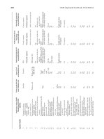
Table 14-2 lists failure modes
for
various devices commonly used
in
production facilities.
In
applying FMEA,
a
mechanical
flow
diagram must
first
be
developed.
As
an
example,
consider
the
check valve
on a
liquid dump line.
It can
fail
Safety
Systems
397
Table
14-2
Failure
Modes
of
Various
Devices
Sensors
FTS
OP
Check
Valves
FTC
Lin
Lex
Signal/Indicator
Fail
to See
Operate Prematurely
Fail
to
Close (Check)
Leak
Internally
Leak
Externally
Orifice
Plates
(Flow
Restrktor)
FTR
BL
Pumps
FTP
POP
LEX
Controllers
FTCL
FTCT
FTCF
OP
FFCLL
FTCHL
FTRP
FTCP
FTAA
Valves
PO
PC
FTO
FTC
Lin
Lex
Fail
to
Restrict
Block
Fail
to
Pump
Pump
to
Overpressurization
Leak Externally
Fail
to
Control Level
Fail
to
Control Temperature
Fail
to
Control Flow
Operate Prematurely
Fail
to
Control
Low
Level
Fail
to
Control High Level
Fail
to
Reduce Pressure
Fail
to
Control Pressure
Fail
to
Activate Alarms
Fail Open
Fail Close
Fail
to
Open
Fail
to
Close
Leak
Internally
Leak Externally
FTI
Switch
FS
PC
FO
Engine
FTD
FXP
Transformer
FTP
General
OF
NP
NS
FP
MOR
NA
Rupture
Disc
RP
FTO
LEX
Meter
FTOP
LEX
BL
Timer
FTAP
FTSP
Fail
to
Indicate
Fail
to
Switch
Fail
Close
Fail Open
Fail
to
Deliver
Deliver
Excess Power
Fail
to
Function
Overflow
Not
Processed
No
Signal
Fail
to
Power
Manual
Override
Not
Applicable
Rupture
Prematurely
Fail
to
Open
Leak
Externally
Fail
to
Operate
Properly
Leak
Externally
Block
Fail
to
Activate
Pump
Fail
to
Stop Pump
one
of
three
ways—it
can
fail
to
close,
it can
leak internally,
or it can
leak
externally.
The
FMEA
will investigate
the
effects that could occur
if
this
particular check valve fails
to
close.
Assuming this happens, some redun-
dancy
that keeps
a
source
from
developing must
be
located
in the
system.
Next,
the
process
would
be
evaluated
for the
second failure mode, that
is,
what
occurs
if the
check valve leaks internally. Next,
the
process would
be
398
Design
of
GAS-HANDLING
Systems
and
Facilities
evaluated
for the
third failure mode
of
this check valve. Check valves
are
easy.
A
controller
has
nine failure modes,
and a
valve
has
six.
In
order
to
perform
a
complete, formal FMEA
of a
production
facility,
each failure mode
of
each device must
be
evaluated,
A
percentage
failure
rate
and
cost
of
failure
for
each mode
for
each device must
be
calculated.
If
the
risk
discounted cost
of
failure
is
calculated
to be
acceptable, then there
are the
proper numbers
of
redundancies.
If
that cost
is not
acceptable,
then
other
redundancies must
be
added until
an
acceptable cost
is
attained,
It
is
obvious that such
an
approach would
be
lengthy
and
would require
many
pages
of
documentation that would
be
difficult
to
check.
It is
also
obvious that such
an
approach
is
still subjective
in
that
the
evaluator
must
make decisions
as to the
consequences
of
each failure,
the
expected
fail-
ure
rate,
and the
acceptable level
of
risk
for the
supposed failure.
This approach
has
been performed
on
several offshore production
facilities
with inconsistent results. That
is,
items that were identified
by
one set of
evaluators
as
required
for
protection
in one
design were
not
required
by
another
set of
evaluators
in a
completely similar
design.
In
addition, potential failure
of
some safety devices
on one
facility caused
evaluators
to
require additional safety devices
as
back-up, while
the
same
group
in
evaluating
a
similar installation that
did not
have
the
initial safe-
ty
devices
at all did not
identify
the
absence
of the
primary safety device
as
a
hazard
or
require back-up safety devices.
It
should
be
clear that
a
complete FMEA approach
is not
practical
for
the
evaluation
of
production facility safety systems. This
is
because
(1)
the
cost
of
failure
is not as
great
as for
nuclear power plants
or
rockets,
for
which this technology
has
proven useful;
(2)
production
facility
design projects cannot support
the
engineering cost
and
lead time associ-
ated with such analysis;
(3)
regulatory bodies
are not
staffed
to be
able
to
critically analyze
the
output
of an
FMEA
for
errors
in
subjective judg-
ment;
and
most importantly,
(4)
there
are
similarities
to the
design
of all
production facilities that have allowed industry
to
develop
a
modified
FMEA
approach that
can
satisfy
all
these
objections,
MODIFIED
FMEA
APPROACH
The
modified FMEA approach evaluates each
piece
of
equipment (not
each device)
as an
independent unit, assuming worst
case
conditions
of
input
and
output. Separators,
flowlines,
heaters,
compressors,
etc.,
func-
tion
in the
same manner
no
matter
the
specific design
of the
facility. That
Safety
Systems
399
is,
they have level, pressure
and
temperature controls
and
valves. These
are
subject
to
failure modes that impact
the
piece
of
equipment
in the
same manner. Thus,
if an
FMEA
analysis
is
performed
on the
item
of
equipment
standing alone,
the
FMEA
will
be
valid
for
that component
in
any
process
configuration.
Furthermore, once every process component
has
been analyzed sepa-
rately
for
worst case, stand-alone conditions, there
is no
additional
safety
risk created
by
joining
the
components into
a
system. That
is, if
every
process component
is
fully
protected based
on its
FMEA analysis,
a
sys-
tem
made
up of
several
of
these components will also
be
fully
protected.
It
is
even possible that
the
system configuration
is
such that protection
furnished
by
devices
on one
process component
can
protect others. That
is,
devices that
may be
required
to
provide adequate protection
for a
component standing alone
may be
redundant once
all
components
are
assembled
in a
system. This procedure
is
outlined below:
1.
For
each
piece
of
equipment (process component), develop
an
FMEA
by
assuming
in
turn
that each
process
upset that could
become
a
potential source occurs. That
is,
assume
a
control
failure,
leak,
or
other event leading
to a
process upset.
2.
Provide
a
sensor
that detects
the
upset
and
shuts-in
the
process
before
an
identified source
of
condition develops.
For
example,
if the
pressure
controller
fails
and the
pressure increases, provide
a
high-
pressure
sensor
to
shut-in
the
process.
If
there
is a
leak
and the
pres-
sure
decreases,
provide
a
low-pressure sensor
to
shut-in
the
process.
3.
Apply FMEA techniques
to
provide
an
independent back-up
to the
sensor
as a
second level
of
defense before
an
identified hazard
is
created.
The
degree
of
reliability
of the
back-up device will
be
dependent upon
the
severity
of the
problem.
For
example, since
overpressure
is a
condition that
can
lead
to
severe hazards,
the
back-
up
device should
be
extremely reliable. Typically,
a
high pressure
sensor would
be
backed
up by a
relief valve.
In
this case
a
relief
valve
is
actually more reliable than
the
high pressure sensor,
but it
has
other detriments associated
with
it.
Oil
leakage,
on the
other
hand,
is not as
severe.
In
this
case,
a
drip
pan to
protect against
oil
pollution
may be
adequate back-up.
4.
Assume that
two
levels
of
protection
are
adequate. Experience
in
applying
FMEA analysis
to
production equipment indicates that
in
many
cases
only
one
level
of
protection would
be
required, given
the
degree
of
reliability
of
shutdown systems
and the
consequences
400
Design
of
GAS-HANDLING
Systems
and
Facilities
of
failure.
However,
it is
more costly
in
engineering time
to
docu-
ment
that only
one
level
is
required
for a
specific installation than
it
is to
install
and
maintain
two
levels. Therefore,
two
levels
are
always
specified.
5.
Assemble
the
components into
the
process system
and
apply
FMEA
techniques
to
determine
if
protection devices
on
some components
provide
redundant protection
to
other components.
For
example,
if
there
are two
separators
in
series,
and
they
are
both designed
for the
same pressure,
the
devices protecting
one
from
overpressure will
also protect
the
other. Therefore, there
may be no
need
for two
sets
of
high
pressure sensors.
The
application
of
this procedure
is
best seen
by
performing
an
FMEA
on
a
simple two-phase separator. Table 14-3 lists those process upsets
that
can be
sensed before
an
undesirable event leading
to a
source
of
con-
dition
occurs.
For
overpressure, primary protection
is
provided
by a
high
pressure sensor that shuts
in the
inlet (PSH).
If
this device
fails,
sec-
ondary
protection
is
provided
by a
relief valve
(PSV).
A
large leak
of gas is
detected
by a
low-pressure
sensor
(PSL) that
shuts
in the
inlet,
and a
check valve (FSV) keeps
gas
from
downstream
components
from
flowing backward
to the
leak. Similarly,
a
large
oil
leak
is
detected
by a
low-level sensor (LSL)
and a
check valve. Back-up
protection
is
provided
by a
sump tank
and its
high-level sensor (LSH)
for
an
oil
leak. That
is,
before
an oil
spill becomes pollution there
must
be a
Table
14-3
FMEA
of a
Separator
Undesirable
Event
Overpressure
Large
Gas
Leak
Large
Oil
Leak
Small
Gas
Leak
Small
Oil
Leak
Inflow
Exceeds
Outflow
High
Temperature
Primary
PSH
PSL and FSV
LSL and FSV
ASH, Minimize
Ignition
Source
Sump Tank (LSH)
LSH
TSH
Secondary
PSV
ASH, Minimize Ignition
Sources
Sump tank (LSH)
Fire
Detection
Manual Observation
Vent
Scrubber (LSH)
Leak
Detection
Devices
Safety
Systems
401
failure
of a
second sensor. Back-up protection
for a gas
leak
then
becomes
the
fire
detection
and
protection equipment
if the
small
leak
were
to
cause
a
fire.
There
is no
automatic back-up
to the
sump tank
LSH
for
a
small
oil
leak. Manual intervention, before containment
is
exceeded
and
oil
pollution results, becomes
the
back-up.
The
primary protection
for
high temperature, which could lower
the
maximum
allowable working pressure below
the
PSV
setting,
is a
high-
temperature
sensor (TSH), which shuts
in the
inlet
or the
source
of
heat,
Back-up
protection
is
provided
by
leak detection devices.
Inflow
exceeding outflow
is
sensed
by a
high-level
sensor
(LSH).
Back-up
protection
is
furnished
by the PSH (to
keep
the
relief
valve
from
operating)
or an LSH in a
downstream vent scrubber
if the
vessel
gas
outlet
goes
to
atmosphere. That
is, a
vent scrubber must
be
installed
downstream
of any
vessel that discharges directly
to
atmosphere.
Once
the
FMEA
is
completed,
the
specific system
is
analyzed
to
deter-
mine
if all the
devices
are
indeed needed.
For
example,
if it is not
possi-
ble
for the
process
to
overpressure
the
vessel, these devices
are not
required,
ff
it is
impossible
to
heat
the
vessel
to a
high enough
level
to
effect
its
maximum working pressure,
the TSH can be
eliminated.
API
RECOMMENDED
PRACTICE
14C
The
modified FMEA approach
has
been used
by the API to
develop
RP14C.
In
this document
ten
different
process components have been
analyzed
and a
Safety Analysis Table (SAT)
has
been developed
for
each
component.
A
sample
SAT for a
pressure vessel
is
shown
in
Table
14-4.
The
fact
that
Tables
14-3
and
14-4
are not
identical
is due to
both
the
subjective natures
of a
Hazard Analysis
and
FMEA,
and to the
fact that
RP14C
is a
consensus standard. However, although
the
rationale
differs
somewhat,
the
devices required
are
identical. (The
"gas
make-up system"
in
Table
14-4
is not
really required
by
RP14C,
as we
shall see.)
The RP 14C
also provides standard reasons allowing
the
elimination
of
certain devices when
the
process component
is
considered
as
part
of
an
overall
system. Figure
14-3
shows
the
Safety Analysis Checklist
(SAC)
for a
pressure vessel. Each safety device
is
identified
by the SAT
(with
the
exception
of
"gas
make-up system")
is
listed.
It
must either
be
installed
or it can be
eliminated
if one of the
reasons listed
is
valid.
(text
continued
on
page 405)
402
Design
of
GAS-HANDLING
Systems
and
Facilities
Table
14-4
Safety
Analysis
Table
(SAT)
Pressure
Vessels
Undesirable
Event
Overpressure
Underpressure
(vacuum)
Liquid
Overflow
Gas
Bio
why
Leak
Excess temperature
Cause
Blocked
or
restricted
outlet
Inflow
exceeds
outflow
Gas
blowby (upstream
component)
Pressure control system
failure
Thermal expansion
Excess heat input
Withdrawals exceed
inflow
Thermal contraction
Open outlet
Pressure control system failure
Inflow
exceeds
outflow
Liquid slug flow
Blocked
or
restricted
liquid
outlet
Level
control system failure
Liquid
withdrawals exceed
inflow
Open
liquid outlet
Level control system failure
Deterioration
Erosion
Corrosion
Impact damage
Vibration
Temperature control system
failure
High inlet temperature
Delectable
Condition
At
Component
High
pressure
Low
pressure
High liquid level
Low
liquid level
Low
pressure
Low
liquid level
High
temperature
Source:
API RP
J4C,
6th
Edition, March 1998.
SAFETY
ANALYSIS CHECKLIST (SAC)-PRESSURE
VESSELS
I
I
i
| a.
High Pressure Sensor
(PSH)
j
l.PSH
installed.
|
j
2.
Input
is from a
pump
or
compressor that cannot develop pres-
!
|
sure greater than
the
maximum allowable working pressure
of
1
the
vessel.
3.
Input source
is not a
wellhead
flow
line(s), production header,
| or
pipeline,
and
each input source
is
protected
by a PSH
that
|
protects
the
vessel.
]
4.
Adequately sized piping without block
or
regulating valves
1
connects
gas
outlet
to
downstream equipment protected
by a
j
PSH
that also protects
the
upstream vessel.
5.
Vessel
is
final
scrubber
in a flare,
relief,
or
vent
system
and is |
designed
to
withstand maximum built-up back-pressure.
6.
Vessel operates
at
atmospheric pressure
and has an
adequate
I
vent
system.
j
1
b. Low
Pressure Sensor (PSL)
{
l.PSL
installed.
j
I 1
i
2.
Minimum
operating pressure
is
atmospheric pressure when
in J
service.
i
|
3.
Each input source
is
protected
by a
PSL,
and
there
are no
pressure
control devices
or
restrictions between
the
PSL(s)
and the
vessel.
4.
Vessel
is
scrubber
or
small trap,
is not a
process
component,
and
adequate protection
is
provided
by
downstream
PSL or
design
function
(e.g., vessel
is gas
scrubber
for
pneumatic safe-
j
ty
system
or
final scrubber
for
flare,
relief,
or
vent system).
5.
Adequately sized piping without block
or
regulating valves
connects
gas
outlet
to
downstream equipment protected
by a i
j
PSL
that also protects
the
upstream vessel.
j
I
c.
Pressure Safety Valve (PSV)
1.
PSV
installed.
2.
Each input source
is
protected
by a PSV set no
higher than
the
maximum
allowable working pressure
of the
vessel,
and a PSV
is
installed
on the
vessel
for fire
exposure
and
thermal expansion.
3.
Each input source
is
protected
by a PSV set no
higher than
the
vessel's maximum allowable working pressure,
and at
least
one
of
these
PSVs
cannot
be
isolated
from
the
vessel.
Figure
14*3.
Safety
analysis
checklist
for
pressure
vessels.
(Source:
API
RP
J4C,
6th
Edition,
March
1998.}
404
Design
of
GAS-HANDLING
Systems
and
Facilities
4.
PSVs
on
downstream equipment
can
satisfy
relief equipment
of !
the
vessel
and
cannot
be
isolated
from
the
vessel.
5.
Vessel
is
final
scrubber
in a
flare, relief,
or
vent system,
is
designed
to
withstand maximum built-up back-pressure,
and
has
no
internal
or
external obstructions, such
as
mist extractors,
back-pressure
valves,
or flame
arresters.
6.
Vessel
is
final
scrubber
in a
flare, relief,
or
vent system,
is
designed
to
withstand maximum built-up back-pressure,
and is
equipped with
a
rupture disk
or
safety
head
(PSE)
to
bypass
any
internal
or
external obstructions, such
as
mist extractors,
back-pressure valves,
or flame
arresters.
j
d.
High Level Sensor (LSH)
l.LSH
installed.
2.
Equipment downstream
of gas
outlet
is not a
flare
or
vent
sys-
tem
and can
safely handle maximum liquid carry-over.
3.
Vessel
function
does
not
require handling separated
fluid
phases.
4.
Vessel
is a
small trap
from
which
liquids
are
manually drained.
e. Low
Level
Sensor
(LSL)
j
1.
LSL
installed
to
protect each liquid outlet.
j
2.
Liquid level
is not
automatically maintained
in the
vessel,
and
the
vessel
does
not
have
an
immersed heating element subject
to
excess temperature.
3.
Equipment downstream
of
liquid outlet(s)
can
safely handle
maximum
gas
rates that
can be
discharged through
the
liquid
outlet(s),
and
vessel does
not
have
an
immersed heating
ele-
ment
subject
to
excess temperature. Restrictions
in the
dis-
charge line(s)
may be
used
to
limit
the gas
flow
rate.
f.
Check
Valve
(FSV)
1.
FSV
installed
on
each outlet.
2.
The
maximum volume
of
hydrocarbons that could
backftow
|
from
downstream equipment
is
significant.
i
3. A
control device
in the
line will effectively minimize backflow.
g.
High Temperature Sensor (TSH)
High
temperature sensors
are
applicable only
to
vessels having
a
heat source.
1.
TSH
installed.
2.
(Deleted
in
Second Edition.)
3.
Heat source
is
incapable
of
causing
excess
temperature.
Figure
14-3.
Continued.
Safety
Systems
405
(text
continued
from
page
401)
The SAC
list provides
a
handy shorthand
for
communicating which
devices
are
required
and the
reasons
why
some
may not be
used.
For
example,
for any
pressure vessel there
is
either
a PSH
required,
or a
rationale numbered, A.4.a,2, A.4.a.3, A.4.a.4, A.4.a.5
or
A.4.a.6 must
be
listed.
It
becomes
a
simple matter
to
audit
the
design
by
checking that
each
device
is
either present
or an
appropriate rationale listed.
The SAT and SAC for
each process component
are
updated periodical-
ly
by API and the
most recent edition should
be
used
in any
design.
Please note that
for
fired
and
exhaust heated components
it may be
nec-
essary
to
include
the
devices required
for a
process tank
or
vessel
as
well
as
those required
for the
heating components.
For
components
not
covered
by RP
14C,
SAT and SAC
tables
can
be
developed
using
the
modified FMEA analysis procedure.
MANUAL
EMERGENCY
SHUTDOWN
The
safety
system should include features
to
minimize damage
by
stop-
ping
the
release
of flammable
substances, de-energizing ignition sources,
and
shutting down appropriate equipment processes. This
is
accomplished
by
locating emergency shutdown
(BSD)
stations
at
strategic locations
to
enable personnel
to
shut down
the
production
facility.
These
ESD
stations
should
be
well marked
and
located conveniently
(50-100
feet)
from
pro-
tected equipment, with back-up stations located some
greater
distance
(250-500
feet)
away.
A
good choice
for
location
is
along
all
exit routes.
At
least
two
widely separated locations should
be
selected.
The ESD can
either shut down
the
entire facility,
or it can be
designed
for
two
levels
of
shutdown.
The
first
level shuts down equipment such
as
compressors, lean
oil
pumps,
and
direct
fired
heaters,
and
either shuts
in
the
process
or
diverts
flow
around
the
process
by
closing
inlet/outlet
block valves
and
opening bypass valves.
The
second
level
shuts down
the
remaining utilities
and
support
facilities,
including generators
and
electrical
feeds.
ANNUNCIATION
SYSTEMS
These systems give early warning
of
impending trouble
to
allow
per-
sonnel
to
take corrective action prior
to a
shut-in,
and
provide
informa-
406
Design
of
GAS-HANDLING
Systems
and
Facilities
tion
about
the
initial
cause
of a
shut-in. They
are a
vital party
of any
large
shutdown
system design.
On
smaller systems, process alarms
may be
minimal
as
there
may not be
sufficient
time
for
personnel
to
react
to the
alarm
before
an
automatic shutdown
is
initiated.
Annunciator
panels should
be in a
central location with alarm annunci-
ators
and
shutdown annunciators grouped separately.
The first
alarm
and
the
first
shut-down normally sound
a
horn
and are
annunciated. This
is
called "first-out indication." Subsequent shutdown
or
alarm signals
received
by the
panel
are
either
not
annunciated
or are
annunciated
in a
different
manner
so
that
the
operator
can
determine
the
initiating cause
of
the
process upset.
Alarm
signals
may
come
from
the
output signal used
to
control
an
operational valve. Shutdown signals should come
from
a
completely
sep-
arate
instrument
not
dependent upon
a
normally used output signal
for
operation.
FUNCTION
MATRIX
AND
FUNCTION
CHARTS
One
method used
to
summarize
the
required
devices
and
show
the
function
performed
by
each device
is
with
a
function
matrix. Figure 14-4
is
a
completed function matrix chart
for the
simple
process
flow
diagram
shown
in
Figure 14-5.
The
function matrix
is
from
RP 14C and is
called
a
SAFE chart. Each component
is
listed
in the
left
hand column with
an
identification number
and
description. Under "Device
I.D.,"
each
of the
devices listed
in the SAC is
listed.
If the
device
is not
present,
the
appro-
priate
SAC
reference number
is
listed.
If the SAC
rationale requires that
another device
be
present
on
another component, that device
is
listed
under
"Alternate
Device,"
if
applicable.
Listed across
the top of the
matrix
are the
various shutdown valves
in
the
facility.
A
mark
in
each
box
indicates
the
function performed
by
each
device
to
assure that
it
protects
the
process component.
By
comparing
the
functions
performed
by
each
device
to the
mechanical
flowsheet, it is
possible
for an
auditor
to
quickly ensure that
the
process
component
is
indeed
isolated.
A
function
matrix
can
also form
the
basis
for the
design
of the
logic
necessary
to
carry
out the
functions that
are to be
performed when
a
sig-
(text
continued
on
page
410)
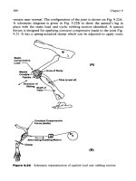
Figure
14-4.
Safety
analysis
function
evaluation
(SAFE)
chart
for
process
flow in
Figure 14.5.
{figure
continued
on
pugf)
Figure
14*4, Continued.
Figure
14*5.
Simple
process
flow
diagram.
410
Design
of
GAS-HANDLING
Systems
and
Facilities
(text
continued
from
page 406)
nal
is
received
from
each device. More frequently,
the
function
matrix
is
used
to
develop
a
"function chart" such
as
that shown
in
Figure 14-6,
and
the
function
chart
is
used
for
designing
the
logic.
It is
possible
to
develop
a
function
chart directly
from
the
facility
flow
diagram. However, some
designers
and
regulatory agencies
feel
that
it is
better
to
develop
a
func-
tion
matrix
first to
ensure that
all
devices required
from the
FMEA
are
considered
and to
clearly show
the end
devices causing
the
shutdown
or
alarm
to
occur.
In
a
function chart each sensing
device
is
listed
on the
left
side
and a
path
is
then drawn showing
the
route
of the
signal from
the
sensing
device
to the
device that performs
the
shutdown
or
alarm
function.
SYMBOLS
Table 14-5 shows symbols used
in RP 14C to
represent
the
various
sensors
and
shutdown devices. Although these symbols
are
used
exten-
sively
in
U.S.
production
facilities, they
are not
used
in
other industries.
They
are
widely used overseas
and are
understood
by all who are
involved
in
production facility design.
In
other countries
and
other
indus-
tries,
the ISA
symbol system
is
more common.
Table 14-6 shows
the
system used
in RP 14C for
identifying equip-
ment items.
The RP
14C
system enables
a
relief valve
on a
specific sepa-
rator
to be
identified
as:
PSV,
MBD-1000
If
there
are
two, they would
be
designated:
PSV,
MBD-1000A
and
PSV,
MBD-1000B
Many
operators
use a
simpler system, using
"V" for
pressure
vessel,
"T"
for
tank,
"P"
for
pump,
"C"
for
compressor,
and
"E"
for
heat
exchanger,
in
which case
the
relief valve
would
be
designated:
PSV,
VI000
or
PSV,
V1000A
and
PSV, V1000B
(text
continued
on
page 418)