ARNOLD, K. (1999). Design of Gas-Handling Systems and Facilities (2nd ed.) Episode 2 Part 10 pptx
Bạn đang xem bản rút gọn của tài liệu. Xem và tải ngay bản đầy đủ của tài liệu tại đây (1.28 MB, 25 trang )
Valves,
Fittings,
and
Piping
Details
461
(text
continued
from
page 453)
Insulation
for
personnel
safety
is
required only when accidental
con-
tact
of the hot
surfaces could
be
made
by
personnel within normal work
or
walk areas. Isolation
may be in the form of
guards
or
barriers
and,
in
special
cases,
warning signs.
Hot
surfaces
associated
with
natural
gas
compressors
and
pumps
han-
dling
volatile
flammable fluids
should
be
insulated since
the
equipment
itself
is a
source
of
hydrocarbon liquids
or
gases. Generators,
electric
motors,
and
engine-driven equipment such
as
fire
water pumps, wireline
units,
welding machines, hydraulic equipment,
and the
like
do not
them-
selves cause
the
area
to
become
classified
from
an
electrical
standpoint,
However, they may be in
a
classified area due to other equipment and
thus
require insulation
or
barriers. Turbo-chargers, exhaust
manifolds,
compressor heads, expansion bottles
and the
like (including associated
piping), which cannot
be
insulated without causing mechanical failure,
are not
normally insulated.
In
these cases, warning signs, barriers,
gas
detectors,
or
other methods
for the
protection
of
personnel
and
minimiz-
ing
exposure
to
hydrocarbon liquids
and
gases
are
acceptable.
MISCELLANEOUS
PIPING
DESIGN
DETAILS
Target
fees
Where
90°
turns
in
piping
are
required, standard long radius ells
(ell
centerline radius equals
1.5
times pipe nominal diameter)
are
usually
used.
In
sandy service,
the
sand
has a
tendency
to
erode
the
metal
on the
outside
of the
bend. Target tees, such
as
shown
in
Figure
15-25,
are
often
specified
for
such service.
The
sand builds
up
against
the
bull plug
and
provides
a
cushion
of
sand that
is
constantly being eroded
and
subject
to
deposition
by the
sand
in the flow
stream.
Chokes
The
flow
of fluid
leaving
a
choke
is in the
form
of a
high-velocity
jet.
For
this reason
it is
desirable
to
have
a
straight
ran of
pipe
of at
least
ten
pipe diameters downstream
of any
choke prior
to a
change
in
direction,
so
that
the jet
does
not
impinge
on the
side
of the
pipe.
462
Design
of
GAS-HANDLING
Systems
and
Facilities
Often
on
high-pressure
wells
two
chokes
are
installed
in the flow-
line—one
a
positive choke
and the
other
an
adjustable choke.
The
adjustable
choke
is
used
to
control
the flow
rate.
If it
were
to cut
out,
the
positive
choke then acts
to
restrict
the flow out of the
well
and
keep
the
well
from
damaging itself. Where there
are two
chokes,
it is
good piping
practice
to
separate
the
chokes
by 10
pipe diameters
to
keep
the jet of
flow
formed
by the
first
choke
from
cutting
out the
second choke.
In
practice this separation
is not
often done because
of the
expense
of
sepa-
rating
two
chokes
by a
spool
of
pipe
rated
for
well shut-in pressure.
It is
much
less expensive
to
bolt
the flanges of
the
two
chokes together.
No
data
has
been collected
to
prove whether
the
separation
of
chokes
is
justi-
fied
from
maintenance
and
safety considerations.
Whenever
a
choke
is
installed,
it is
good
piping practice
to
install
block
valves
within
a
reasonable distance upstream
and
downstream
so
that
the
choke bean
or
disc
can be
changed without having
to
bleed down
a
long length
of
pipeline.
A
vent
valve
for
bleeding pressure
off the
seg-
ment
of the
line containing
the
choke
is
also needed. This
is
particularly
true
in
instances where
a
positive choke
is
installed
at the
wellhead
and
an
adjustable choke
is
installed hundreds
of
feet
away
in a
line heater.
If
block
valves
are not
installed downstream
of the
positive choke
and
upstream
of the
adjustable choke,
it
would
be
necessary
to
bleed
the
entire
flowline
to
atmosphere
to
perform maintenance
on
either choke,
Flange
Protectors
The
full
faces
of flanges
never really
touch
due to the
gaskets
or
rings
that
cause
the
seal.
The
space between
the two flange
faces
is a
very
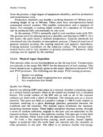
Figure
15-25.
Target tee.
Valves,
Fittings,
and
Piping
Details
463
good spot
for
corrosion
to
develop,
as
shown
in
Figure
15-26.
Flange
protectors made
of
closed-cell
soft
rubber
are
sometimes used
to
exclude
liquids
from
penetrating this
area.
Stainless-steel bands
and
grease
fit-
tings
are
also used.
Closed-cell
flange
protectors
are
much
less
expensive than stainless
bands. However,
if not
installed properly
they
can
actually accelerate cor-
rosion
if a
path
is
created
through
the
material
to
allow moisture
to
enter,
Flange protectors should
not be
used
in
H
2
S
service. They
may
trap
small
leaks
of
sour
gas and
keep them
from
being dispersed
in the
atmosphere.
Figure
15-26.
Flange
protector
types.
464
Design
of
GAS-HANDLING
Systems
and
Facilities
Vessel
Drains
If
vessel
drain
valves
are
used often,
there
is a
tendency
for
these
valves
to cut
out.
As the
valve
is
opened
and
shut, there
is an
instanta-
neous flow
of a
solid
slurry
across
the
valve that
creates
an
erosive
action. Figure 15-27 shows
a
tandem valve arrangement
to
minimize this
potential problem.
To
drain
the
vessel,
the
throttling valve
is
shut
and one
or
more drain valves
are
opened. These valves open with
no flow
going
through
them. Then
the
throttling
valve
is
opened.
To
stop draining,
the
throttling valve
is
closed,
flow
goes
to
zero,
and the
drain valves
are
shut.
The
throttling valve will eventually
cut
out,
but it can be
easily repaired
without
having
to
drain
the
vessel
Vessel
drain systems
can be
very dangerous
and
deserve
careful
atten-
tion.
There
is a
tendency
to
connect high-pressure
vessels
with low-pres-
sure vessels through
the
drain system.
If a
drain
is
inadvertently
left
open, pressure
can
communicate through
the
drain system
from
the
high-
pressure vessel
to the
low-pressure vessel.
If
this
is the
case,
the low
pressure vessel relief valve must
be
sized
for
this potential
gas
blowby
condition.
The
liquid drained from
a
vessel
may flash a
considerable quantity
of
natural
gas
when
it flows
into
an
atmospheric drain header.
The gas
will
find
a way out of the
piping system
and
will seek
the
closest
exit
to
atmosphere that
it can find.
Thus,
a
sump collecting vessel drains
must
be
vented
to a
safe
location.
Figure
15*27.
Drain
valves
for a
separator.
Valves,
Fittings,
and
Piping
Details
465
Open
Drains
Open,
gravity drains should
not be
combined
with
pressure vessel
drain systems.
The gas flashing
from
vessel liquids
may
exit
an
open
drain
system
at any
point
and
create
a
hazard.
On
open drain piping leaving buildings,
a
liquid
seal
should
be
installed
as
further
protection
to
assure that gases flashing
from
liquids
from
other locations
in the
drain
system
will
not
exit
the
system
in the
building.
The
elevation
of
gravity drain systems must
be
carefully checked
to
assure
that liquids will
flow to the
collection point without exiting
the
piping
at an
intermediate
low
point.
Piping
Vent
and
Drain
Valves
At
high points
in
piping, vent valves
are
required
to
remove
air for
hydrotesting
and for
purging
the
system.
At low
points, drain valves
are
required
to
drain liquids
out of the
system
to
perform maintenance. Nor-
mally,
vent
and
drain valves
are
H-in.
or
%-in.
ball valves.
Control
Stations
Whenever
it is
necessary
to
control
the
process
level, pressure, temper-
ature,
etc.,
a
control station
is
installed.
A
control station
may be as
sim-
ple
as a
single
control
valve
or it may
contain several control valves,
block valves, bypass valves, check valves,
and
drain
or
vent valves.
Where there
is a
control valve, block valves
are
often
provided
so the
control valve
can be
maintained without having
to
drain
or
bleed
the
pressure
from
the
vessel. Typically,
the
safety-systems analysis would
also
call
for a
check valve
at
this point
to
prevent
backflow.
Drain
or
vent
valves
are
often
installed
to
drain liquid
or
bleed
pressure
out of the
sys-
tem
so
that
the
control valve
can be
maintained.
In
smaller installations
drain
and
vent valves
may not be
provided
and the
line
is
depressured
by
backing
off
slightly
on flange
bolts
(always leaving
the
bolts
engaged
until
all
pressure
is
released)
or
slowly unscrewing
a
coupling.
This
is not
a
good practice although
it is
often
used
for
small-diameter, low-pressure
installations.
Bypass
valves
are
sometimes installed
to
allow
the
control valve
to be
repaired without shutting
in
production.
On
large, important streams
the
bypass
could
be
another control valve station. Manual bypass valves
are
466
Design
of
GAS-HANDLING
Systems
and
Facilities
more common.
The
bypass valve could
be a
globe valve
if it is
anticipat-
ed
that flow will
be
throttled through
the
valve manually during
the
bypass operation,
or it
could
be an
on/off valve
if the
flow
is to be
cycled.
Because
globe
valves
do not
provide
positive
shutoff,
often
globe-bypass valves have
a
ball
or
other
on/off
vaive
piped
in
series
with
the
globe valve.
The
piping around
any
facility,
other than
the
straight
pipe
connecting
the
equipment,
is
made
up
primarily
of a
series
of
control stations. Flow
from
one
vessel
goes
through
a
control station
and
into
a
piece
of
pipe
that
goes
to
another
vessel.
In
addition
to
considering
the use of
block
valves,
check valves,
etc.,
all
control stations should
be
designed
so
that
the
control valve
can be
removed
and any
bypass valve
is
located above
or
on a
level
with
the
main control valve.
If the
bypass
is
below
the
con-
trol
vaive,
it
provides
a
dead space
for
water accumulation
and
corrosion.
CHAPTER
16
Prime
Movers
*
Both reciprocating engines
and
turbines
are
used
as
prime movers
in
production facilities
to
directly drive pumps, compressors, generators,
cranes,
etc.
Reciprocating
engines
for oil
field
applications
range
in
horsepower
from
100 to
3,500,
while
gas
turbines range
from
1,500
to in
excess
of
75,000.
Prime movers
are
typically
fueled
by
natural
gas or
diesel.
Dual
fuel
turbine units exist that
can run on
natural
gas and can
automatically
switch
to
diesel.
So-called
"dual fuel" reciprocating engines
run on a
mixture
of
diesel
and
natural
gas.
When natural
gas is not
available, they
can
automatically switch
to
100%
diesel.
Most prime movers
associated
with
producing facilities
are
typically natural
gas
fueled
due to the
ready
availability
of
fuel.
Diesel
fueled
machines
are
typically used
to
provide
stand-by
power
or
power
for
intermittent
or
emergency users such
as
cranes, stand-by generators, firewater pumps,
etc.
Due
to the
extremely wide variety
of
engines
and
turbines available,
this
discussion
is
limited
to
those normally used
in
production facilities.
The
purpose
of
this chapter
is to
provide facility engineers with
an
under-
standing
of
basic engine operating principles
and
practices
as
necessary
for
selection
and
application.
The
reader
is
referred
to any of the
many
texts available
on
engine
and
turbine design
for
more in-depth
discussion
of
design details.
^Reviewed
for the
1999
edition
by
Santiago
Pacheco
of
Paragon
Engineering
Services, Inc.
467
468
Design
of
GAS-HANDLING
Systems
and
Facilities
RECIPROCATING
ENGINES
Reciprocating engines
are
available
in two
basic
types—two-stroke
or
four-stroke
cycle. Regardless
of the
engine type,
the
following
four
func-
tions
must
be
performed
in the
power
cylinder
of a
reciprocating engine:
1.
Intake—Air
and
fuel
are
admitted
to the
cylinder,
2.
Compression—The
fuel
and air
mixture
is
compressed
and
ignited.
3.
Power—Combustion
of the
fuel
results
in the
release
of
energy. This
energy release results
in
increase
in
temperature
and
pressure
in the
cylinder.
The
expansion
of
this mixture against
the
piston converts
a
portion
of the
energy released
to
mechanical energy.
4.
Exhaust—The
combustion
products
are
voided
from
the
cylinder
and
the
cycle
is
complete.
In
this
manner
the
chemical energy
of the
fuel
is
released. Some
of the
energy
is
lost
in
heating
the
cylinder
and
exhaust
gases.
The
remainder
is
converted
to
mechanical
energy
as the
expanding
gases
move
the
piston
on
the
power stroke. Some
of the
mechanical energy
is
used
to
overcome
internal
friction
or to
sustain
the
process
by
providing
air for
combustion,
circulating
cooling water
to
remove heat
from
the
cylinder,
and
circulat-
ing
lube
oil to
minimize friction.
The
remainder
of the
energy
is
available
to
provide external work.
The
amount
of
external work that
can be
devel-
oped
by the
engine
is
termed
its
"brake horsepower"
or
bhp.
The
amount
of
work required
to
sustain
the
engine
is
termed
its
"friction
horsepower"
or
fhp.
The
work developed
by the
power cylinders
is
termed
the
"indi-
cated
horsepower"
or
ihp.
The
indicated
horsepower
is the sum of
both
the
friction
horsepower
and the
brake horsepower.
ihp = bhp + fhp
Four-Stroke
Cycle
Engine
The
four-stroke cycle engine requires
four
engine strokes
or 720
degrees
of
crankshaft rotation
to
complete
the
basic functions
of
intake,
compression.,
power,
and
exhaust.
All flow
into
and
away
from
the
cylin-
ders
is
controlled
by
valves directly operated
by a
camshaft that
is
driven
at
1
A
engine speed. Figures
16-1
and
16-2 illustrate
a
cross
section
and an
idealized
P-V
diagram
for a
four-cycle spark-ignited engine, respectively.
Prime
Movers
469
Figure
16-1.
Cross
section
of
4-cycle,
spark-ignited engine.
Intake
Stroke
(Point
1 to
Point
2)
With
the
intake valve open,
the
piston movement
to the
right creates
a
low
pressure region
in the
cylinder, which causes
air and
fuel
to
flow
through
the
intake valve
to fill the
cylinder.
Compression
Stroke
(Point
2 to
TDC)
The
intake valve
is now
closed
as the
piston moves
from
the
bottom
dead center (BDC)
to top
dead
center (TDC), compressing
the
fuel/air
mixture.
At
Point
3,
just prior
to
TDC,
a
spark
ignites
the
fuel/air mixture
and
the
resulting combustion causes
the
pressure
and
temperature
to
begin
a
very rapid rise within
the
cylinder.
Power
Stroke
(TDC
to
Point
4)
Burning
continues
as the
piston reverses
at TDC and
pressure rises
through
the first
portion
of the
"power"
or
"expansion"
stroke.
It is the
increase
in
pressure
due to
burning
the
fuel
that
forces the
piston
to the
right
to
produce
useful
mechanical power.
The
piston moves
to the right
until
BDC is
reached.
470
Design
of
GAS-HANDLING
Systems
and
Facilities
VOLUME
%
of
Piston
Displacement
Figure
16-2.
Idealized
P-V
diagram
for a
4-cycie,
spark-ignited
engine.
Exhaust
Stroke
(Point
4 to
Point
1)
With
the
exhaust valve open,
the
upward stroke
from
BDC to TDC
creates
a
positive pressure within
the
cylinder, which forces combustion
products
from
the
cylinder
on the
"exhaust" stroke.
Two-Stroke
Cycle Engine
Two-stroke cycle engines require
two
engine strokes
or 360
degrees
of
crankshaft
rotation
to
complete
the
basic functions
of
intake, compres-
sion,
power,
and
exhaust.
Figures
16-3
and
16-4
illustrate
a
cross section
and
a
P~V
diagram
for a
two-cycle engine, respectively.
In
this common
type
of
engine,
the
piston
in its
traverse covers
and
uncovers passages
or
Prime
Movers
471
Figure
16-3.
In
this
cross
section
of a
two-cycle
engine,
only
a
trained
eye can
identify
the
engine
porting
that
distinguishes
it
from
a
four-cycle
engine.
(Courtesy
of
Electro-Motive
Division,
General
Motors Corp.,
and
Stewart
and
Stevenson
Services,
Inc.)
ports
in the
lower cylinder wall that control
the
inflow
of air and the
out-
flow
of
exhaust gases. This type
of
engine
is
called
a
piston-ported
engine. Inasmuch
as
both intake
and
exhaust ports
are
opened
at
every
piston
traverse, there
are no
periods
of
negative pressure
to
induce
air nor
of
high positive pressure
to
completely expel exhaust
gases.
While
a
two-
cycle engine
has the
ability
to
produce power with each down motion
of
the
piston,
it
is at the
expense
of
some external means
of
compressing
enough
air to fill the
cylinder
and to
expel
the
combustion products
from
the
previous
cycle
("scavenge"
the
cylinder)
as
well.
472
Design
of
GAS-HANDLING
Systems
and
Facilities
Figure
16-4.
Idealized
P-V
diagram
for a
2-cycle
engine.
The
Compression Stroke
As
the
piston begins
its
leftward
stroke
from
bottom dead center
(BDC),
both inlet
and
exhaust ports
are
uncovered
and air
from
some
external source
is
flowing
through
the
cylinder. Directional control
is
provided
through port
and/or
piston design
to
ensure
the
most complete
cylinder scavenging possible.
At
Point
2, the air
intake
is
closed,
but
compression does
not
begin
until
the
exhaust port
is
covered also. Shortly
after
the
exhaust port
is
closed
and
compression
of the
trapped
air
begins,
fuel
is
injected
at
Point
3
into
the
cylinder through
a
high pressure
fuel
valve.
At
Point
4,
just
prior
to
completion
of the
compression stroke,
a
spark ignites
the
fuel/air
mixture
and the
pressure rises rapidly through
the
remainder
of the
com-
pression stroke
and the
beginning
of the
"power"
stroke,
Prime
Movers
473
Power
Stroke
During
the
power stroke,
the
piston
is
forced
to the right,
producing
power.
At
Point
5, the
exhaust port opens
and
terminates
the
power
pro-
ducing
portion
of the
cycle
as
exhaust gases escape
to the
atmosphere.
As
the
intake port
is
uncovered, Point
6, air
begins
to flow
through
the
cylin-
der and out of the
exhaust port "scavenging"
the
remaining exhaust gases
and
filling the
cylinder with
fresh
air to
begin
the
cycle again.
On
piston
ported
engines
both
ports
are
open during
the
part
of the
cycle
when
the
intake port
is
open.
Due to
this
fact,
the
large industrial two-stroke cycle
engines
use
fuel
injection valves
in
lieu
of
carburetion
to
maintain
fuel
economy.
Otherwise,
unburned
fuel
would
be
passed through
the
cylin-
der
directly
to the
exhaust manifold.
The
area contained within
the P-V
diagram represents
the
total
mechanical work performed
by the
piston. Some
of
this
work
is
required
to
sustain
the
cycle
and
must
be
subtracted from
the
work calculated
from
the
P-V
diagram
to
determine
the
total external work available
from
the
piston,
Comparison
of
Two-Cycle
and
Four-Cycle
Engines
Both
two-
and
four-stroke
cycle
engines
are
used
in
commercial appli-
cations.
For the
purpose
of
this discussion, however, comments will
be
limited
to
applications normally encountered
in the oil and gas
industry.
Some
of the
advantages
and
disadvantages associated with each
engine
type
are as follows:
Two-Stroke Cycle
Engines
Advantages
1.
Relatively smaller size
for
comparable horsepower machines.
2.
Reduced weight over similar horsepower four-stroke engines.
3.
Fewer mechanical parts.
4.
Reduced maintenance.
5.
Generally simplified maintenance procedures.
6.
Reduced overall installation cost
due to
size
and
weight.
Disadvantages
1.
Scavenging system required
to
allow self-starting.
2.
Prone
to
detonation
at
high ambient temperatures.
474
Design
of
GAS-HANDLING
Systems
and
Facilities
3.
Lower exhaust temperature reduces
available
waste
heat,
4.
Power cylinders require
frequent
balancing.
5.
Very
sensitive
to
lube
oil to
prevent excessive port carboning,
Four-Stroke
Cycle
Engines
Advantages
1.
Substantial exhaust heat available
for
waste heat recovery.
2.
Reduced detonation tendency
at
high ambient temperatures.
3.
Requires
infrequent
power cylinder balancing.
Disadvanl^ges
1.
Higher comparable package weight
and
space requirements.
2.
More complex maintenance.
3.
More expensive
facility
costs.
Both
engine types
are
available
in
horsepower ranges
to
satisfy
most
any
application. Two-stroke engines
are
generally
of
slow
speed
(300-600
rpm)
design with horsepower exceeding 2000 bhp.
The
four-
stroke engines
are
available over
all
speed ranges. Four-stroke engines
tend
to be
used
for
lower horsepower applications although some
are
available
in
sizes exceeding
3000
bhp.
Engine
Speed
The
selection
of a
machine must also include
the
desired speed
at
which
it
will
operate.
The
normally accepted classifications are:
Slow
speed—300-600
rpm
Intermediate
speed—600-900
rpm
High
speed—
> 900 rpm
In
general, slower speed units will
be
larger, heavier,
and
more costly
than
higher speed units. Slower speed units have
the
advantages
of
high-
er
reliability, greater
fuel
efficiency,
and
lower maintenance costs than
higher
speed machines.
The
overall economics
of
initial capital cost, reli-
ability,
fuel
cost,
maintenance costs, etc., must
be
considered
to
deter-
mine
the
most appropriate version
for a
particular installation.
Prime
Movers
475
Naturally
Aspirated
vs.
Supercharged
Engines
Air
is
supplied
to the
power cylinders
by
either natural
air flow
associ-
ated
with
the
engine
or by
some external
means.
Engines that
use no
external means
of air
supply
are
termed
to be
naturally
aspirated.
Those
with
some external
air
supply
are
generally termed "supercharged."
The
horsepower developed
by an
engine
is
dependent
on its
supply
of
air.
The
more
air
mass contained
in a
cylinder
at
ignition
the
more
fuel
that
can be
burned
and the
more horsepower that will
be
developed
by the
cylinder.
Four-stroke cycle machines
are
available
in
either
naturally
aspirated
or
supercharged versions. Superchargers available include engine-driven
blowers
or
"turbochargers."
Except
for
some
small
engines,
the
tur-
bocharger
is the
most common method
of
supercharging these engines.
Turbochargers
use the
expansion
of
exhaust
gas to
pump combustion
air
to an
engine. Exhaust
gas is
directed through
a set of
nozzles
to
drive
a
turbine wheel. Directly connected
to the
exhaust turbine
is an air
com-
pressor turbine that delivers combustion
air to the
power cylinders. Thus,
back-pressure
is put on the
engine exhaust, reducing power slightly,
but
the net
effect
of the
increase
in air
mass
flow
available
for
combustion
is
to
increase horsepower.
Care must
be
exercised when
turbocharging
an
engine.
As
more
air is
forced
into
the
cylinders,
the
cylinder pressures associated
with
combus-
tion
will
increase. Controls must
be
provided
to
limit these pressures
to
prevent
engine damage. Excessive pressures will result
in gas
igniting
prior
to the
spark activating,
and/or
overstress
of the
engine. Substantial
engine damage
can
result
from
either.
Although
turbocharging
an
engine increases
the
bhp
for a
nominal
additional
capital cost,
it has the
disadvantage
of
increasing
maintenance
costs
and
decreasing engine reliability.
Two-stroke
cycle machines
must
be
equipped with
a
scavenge
air
sys-
tem
that
may
include
a
separate scavenge
air
cylinder, gear-driven blower,
or
turbochargers.
It
should
be
noted, however, that
a
method must
be
pro-
vided
to
supply
a
turbocharged
two-stroke cycle
engine
with
air to
start.
Carburettor)
and
Fuel
Infection
Reciprocating engines
are
classified
as
either spark ignited
or
com-
pression
ignited.
Fuel
is
supplied
to
spark ignited
engines
by
either
a
car-
buretor
or
fuel
injection. Fuel
is
supplied
to
compression ignited
(diesel)
engines
by
fuel
injection.
476
Design
of
GAS-HANDLING
Systems
and
Facilities
Carhuretion
Fuel must
be
supplied
to an
engine
in a
manner determined
by
operat-
ing
conditions.
As
engine load changes, changes
in
fuel
flow are
required
to
maintain correct
fuel
mixtures.
The flow of the air is
regulated
by a
throttling device
as
shown
in
Figure
16-5.
The
throttle device
is
con-
trolled
by an
engine speed control device
or by a
"governor," which
con-
trols engine speed
to a
pre-set value.
The
pressure
differential
created
by
air
flow
through
the
venturi
is
used
to
regulate
fuel
flow to the
range
of
0,06
to
0.07
Ib
of
fuel
per
Ib
of
air.
Fuel
Injection
This
is
another method
of
supplying
an
engine with
the
correct
quanti-
ty
of
fuel.
Three types
of
fuel
injection
are
used:
Figure
16-5.
Cutaway view
of
carburetor.
Prime
Movers
477
1.
Inlet port injection
is
used
with
liquid
fuel,
spark ignition engines
only.
Fuel
is
injected into
the
inlet port
and
mixed with
the
inlet air.
The
injection
process
may be
either timed
or
continuous.
2.
Early cylinder injection
is
used only with spark ignition
engines.
Fuel
is
admitted into
the
cylinder during
the
intake
or
compression
stroke.
This
is the
injection
method used
on the
large two-stroke
cycle engines
to
prevent loss
of
fuel
during
the
scavenging process.
3.
Late cylinder injection
is
typically used
for
diesel
engines. Fuel
is
admitted
to the
cylinder
as the
piston
is
nearing
top
center.
Very
high
injection pressures
are
required
for
proper
fuel
atomization
and
combustion
control. Pressures
can
exceed
20,000
psi for
this type
of
injection.
Engine
Shutdown
System
Most engines
are
operated
in an
unattended manner. Shutdown safety
devices must
be
provided
to
prevent engine damage
in
case
of a
malfunc-
tion.
Some
of the
more common engine shutdowns are:
1.
Low
lube
oil
pressure
2.
Engine overspeed
3.
Engine high
temperature—jacket
water
4.
Engine high
temperature—lube
oil
5.
Low
jacket water pressure
6.
High vibration
7.
Low
lube
oil flow—lube oil to the
stroke power cylinder
8.
High bearing temperature
9.
Low
fuel
gas
pressure
This
is not to be
taken
as a
complete
shutdown
list.
Installation
and
oper-
ating
requirements
may
dictate
other
safety
precautions.
This
list
does
not
include
any
safety
devices that would
be
associated
with
the
driven
equipment.
GAS
TURBINE
ENGINES
Gas
turbines
differ
from
conventional internal-combustion engines
in
the
manner
in
which
the
expanded gases
are
employed.
The
principle
of
operation
is to
direct
a
stream
of hot
gases against
the
blading
of a
tur-
bine
rotor.
As
shown
in
Figures
16-6
and
16-7,
the gas
turbine consists
of
478
Design
of
GAS-HANDLING
Systems
and
Facilities
Figure
16-6.
Schematic
of
single-shaft
gas
turbine.
Figure
16-7.
Cutaway
view
of
typical
turbine.
Prime
Movers
4J9
three basic sections:
the air
compressor section
in
which
air is
com-
pressed
in a
compressor,
the
combustor
section
in
which
fuel
is
mixed
with
the
compressed
air and
burned,
and
the
turbine section where
work
is
extracted
from
the hot
gases.
The
expansion
of the
gases against
the
blades
of the
turbine provide power
to
drive
an
external load
such
as a
pump
or
compressor,
as
well
as
power
to
drive
the air
compressor.
The
result
is a
smooth running, steady
flow
machine.
A
significant difference between
gas
turbines
and
reciprocating
engines
is
that
gas
turbines
use
much more air.
For
example,
an
1100-hp
gas
turbine (Solar Saturn) handles approximately
12
lb
m
/sec
or
almost
22
tons
of air per
hour.
A
comparable reciprocating engine will
use
only
about
1
A
that amount. Piston engines
use
almost
all the air for
combustion
(a
small amount
may be
used
for
cylinder scavenging), while turbines
use
only about
25% of the air flow for
combustion.
The
remainder,
or
about
75%,
is
used
for
cooling
and to
obtain
the
mass
flow
required
to
operate
the
turbine.
Fundamentals
The
basic
gas
turbine engine
is
described
by the
idealized Brayton
air
cycle
as
shown
in
Figure 16-8.
In
this cycle,
air
enters
the air
compressor
(also called
the
"gas producer")
at
Point
1
under normal atmospheric
pressure
and
temperature,
PI
and
Tl.
It is
then isentropically compressed
to
Point
2
where
the
pressure
and
temperature
are now P2 and T2.
From
Point
2 the air flows
into
the
combustion chamber where
fuel
is
injected
and
burned
at
constant pressure, raising
the
temperature
to T3 and
expanding
the
volume
to V3.
From
the
combustion chamber
the
heated
gases enter
the
power turbine where they perform work
by
turning
the
output
power shaft.
These
gases expand
to
near atmospheric pressure
and
are
exhausted
at
greater than atmospheric temperature
at
Point
4.
Ideally,
it
would
be
possible
to
have
the
same
fluid
going through this circuit
all
the
time,
and the
step
from
Point
4 to
Point
1
would
be a
cooling process.
Actually,
this step
is
accomplished
by
exhausting
to
atmosphere
and
tak-
ing
in a new
charge
of
air.
In
this cycle, approximately
30% of the
fuel
consumed
is
available
as
power output.
In
addition, approximately
30% is
used
to
drive
the air
compressors,
30% is
contained
in the hot
exhaust gases,
and
10% is
lost
to
radiation
and the
lube
oil
system.
Simple cycle industrial
gas
turbines burn more
fuel
than comparable
reciprocating
machines. There are, however, several methods available
to
480
Design
of
GAS-HANDUNG
Systems
and
Facilities
Figure
16-8.
This
Brayton
cycle describes
the
basic
operation
of a gas
turbine.
Figure
16-9.
The
regeneration
cycle
of a gas
turbine
uses
recovered exhaust
heat
to
preheat
the
compressed
air
prior
to
combustion.
Prime Movers
481
either reduce direct
fuel
consumption
or use the
available
exhaust heat
to
reduce overall
facility
fuel
requirements. Three common methods
avail-
able
are
regeneration, waste heat recovery,
and
combined cycle opera-
tion.
Regeneration
or
recouperation uses
a
heat exchanger
in
which exhaust
heat
is
recovered
to
preheat
the
compressed inlet
air
prior
to the
combus-
tion
chamber
as
shown
in
Figure
16-9.
The
increased
combustion
air
temperature
reduces
the
fuel
requirement
to
maintain power turbine inlet
temperatures.
This
heat recovery
can
increase
the
turbine's thermal
efficiency
to
approximately
35 to
40%.
The
available horsepower output
of the
unit
will drop
slightly
because
of
increased
pressure
losses
due to the
regener-
ator. Initial costs
and
additional maintenance expense
of a
regenerative
cycle usually outweigh
its
advantages
for
most producing installations.
However, where
fuel
prices
are
high
and
there
are no
waste heat users,
the
use
of the
regenerative cycle should
be
considered.
Another method
of
increasing
the
overall cycle
efficiency
is to use the
waste heat energy
in the
exhaust
air to
heat
process
fluids
as
depicted
in
Figure
16-10.
This
is a
direct
savings
in
fuel
gas
that would otherwise
be
consumed
in
direct-fired heaters. Overall thermal
efficiencies
can be as
high
as 50 to 60% in
this type
of
installation.
The
energy
in the
turbine exhaust stream
can
also
be
used
to
generate
steam
as
shown
in
Figure
16-11.
This
is
called
a
combined cycle since
mechanical energy
is
available both
from
the
power turbine output
and
from
the
output
of the
steam turbine.
The
energy used
to
drive
the
steam
turbine contributes
to the
overall thermal
efficiency
as the
steam
is
gener-
ated
without
the
expense
of any
additional
fuel
consumption.
A
combined
cycle
system
can
increase overall thermal
efficiency
to the 40%
range,
Figure
16-10.
This
schematic
illustrates
how
waste
heat
can be
recovered
and
used
to
heat
process
fluids.
482
Design
of
GAS-HANDLING
Systems
and
Facilities
Figure
16*11.
The
combined
cycle
of
waste heat recovery
can be
used
to
generate
steam,
Effect
of
Ambient
Conditions
Available
horsepower
from
a gas
turbine
is a
function
of air
compres-
sor
pressure ratio, combustor temperature,
air
compressor
and
turbine
efficiencies,
ambient temperature,
and
barometric pressure. High ambient
temperatures
and/or
low
barometric pressure will reduce available horse-
power while
low
ambient temperatures
and/or
high barometric pressure
will
increase
available
horsepower.
All
industrial turbines will have high-
temperature
protection,
but in
areas subject
to
very
low
ambient tempera-
tures
horsepower
limiting
may be
required.
Figure
16-12
shows
the
effect
of
ambient temperature
on the
horse-
power output
of a
typical two-shaft
gas
turbine
engine.
At
high tempera-
tures
the
horsepower
is
limited
by the
maximum allowable power turbine
inlet
temperature.
At low
ambient temperatures,
the
available horsepower
is
limited
by the
maximum allowable
air
compressor speed.
Where
hot
ambient temperatures
are
expected, overall turbine
efficien-
cy
and
horsepower output
can be
increased
by
installing
an
evaporative
cooler
in the
inlet. Inlet
air
flows
through
a
spray
of
cold water.
The
tem-
perature
of the
water
and the
cooling
effect
caused
by the
inlet
air
evapo-
rating some
of the
water cools
the
inlet air.
In
desert areas where
the
inlet
air
is dry and
thus able
to
evaporate more water before becoming saturat-
ed
with water vapor, this process
is
particularly
effective
at
increasing
turbine
efficiency.
Effect
of Air
Compressor
Speed
The
horsepower output
of a gas
turbine
is a
direct
function
of
flow
rate
across
the
power turbine, which
is a
function
of air
compressor speed
and
combustion
temperature. Figure 16-13 shows
the
relationship between
Prime
Movers
483
Figure
16-12.
Effect
of
ambient
temperature on
turbine
performance.
air
compressor speed
and
available horsepower.
For
example,
a 10%
drop
in air
compressor speed will result
in a
drop
of
almost
50% in
avail-
able horsepower. Thus,
air
compressor
speed
is
critical
to
output
horse-
power
and
small speed changes
can
result
in
large changes
in
available
horsepower,
Single-'
vs.
Multi-Shaft
Turbines
Industrial
gas
turbines
are
available
as
either
single-shaft
or
multi-
shaft
engines.
The
turbine illustrated
in
Figure
16-6
has a
single
shaft.
Both
the air
compressor
and the
power turbine section operate
off the
same
shaft
and
thus rotate
at the
same speed.
As
illustrated
in
Figure
16-
14, in a
multi-shaft
unit some
of the
power turbine wheels
are on the
same
shaft
as the air
compressor, while
the
remainder
of the
power
tur-
bine wheels
are on a
separate
shaft
that provides power
to the
driven
equipment.
The
speed
of the
wheels
of the
power turbine that provide
the
484
Design
of
GAS-HANDLING
Systems
and
Facilities
Figure
16-13.
Air
compressor discharge pressure
as
a
function
of its
speed.
Figure
16-14.
This
two-shaft
turbine
illustrates
how
power
turbine
wheels
may be
placed
on
separate
shafts.
Prime
Movers
485
output
work
and the
speed
of the
wheels
of the
power turbine driving
the
air
compressor
are
independent
of
each other.
The
output
shaft
speed
can
be
faster
or
slower than
the air
compressor depending upon
the
require-
ments
of the
external load.
Figure
16-15 illustrates
the
performance characteristics
of a
single-
shaft
turbine.
In
this case
the
minimum speed
is
governed
by the
surge
limit
of the air
compressor
and the
maximum power
is
governed
by the
maximum
allowable temperature
at the
inlet
of the
power turbine section.
Thus,
the
power turbine
has a
very narrow speed range over which
it can
operate.
At
speeds below
80%
there
is a
significant loss
in
power output.
This type
of
machine
is
more desirable
in
constant-speed, variable-load
applications, such
as
powering
a
generator, since
the
speed
of the
genera-
tor
must
be
held constant
no
matter what
the
load.
In an
application
requiring
variable
output
speeds,
such
as a
pump
or gas
compressor,
when
the
load declines below
the
capacity
of the
pump
or
compressor
at
the
minimum power turbine operating speed,
it
becomes necessary
to
bypass
gas
from
the
discharge
to the
suction
of the
pump
or gas
compres-
sor to
maintain
the
minimum
flow.
This
condition
is not
desirable
as
horsepower
and
fuel
gas are
wasted
in
recycling
the
process stream.
Another
disadvantage
of
single-shaft turbines
is
that
the
starting horse-
power
requirements
may be
large.
To
keep this starting requirement
as
Figure
16-15.
Performance
characteristics
of a
single-shaft
turbine.