UML WEEKEND CRASH COURSE phần 4 docx
Bạn đang xem bản rút gọn của tài liệu. Xem và tải ngay bản đầy đủ của tài liệu tại đây (378.39 KB, 35 trang )
Saturday Morning94
The Class diagram
The Class diagram represents classes, their component parts, and the way in which classes of
objects are related to one another. A class is a definition for a type of object. It’s really not
much different from what you find in a dictionary. If you want to find out what a widget is,
you look up the word widget. You would find a description of what a widget looks like, its
purpose, and any other pertinent information for understanding widgets. There are no
actual widgets in the dictionary, only descriptions. There are no real objects in a class, only
descriptions of what a particular type of object looks like, what it can do, and what other
objects it may be related to in some way.
To document this information, the Class diagram includes attributes, operations, stereo-
types, properties, associations, and inheritance.
¼
Attributes describe the appearance and knowledge of a class of objects.
¼
Operations define the behavior that a class of objects can manifest.
¼
Stereotypes help you understand this type of object in the context of other classes
of objects with similar roles within the system’s design.
¼
Properties provide a way to track the maintenance and status of the class definition.
¼
Association is just a formal term for a type of relationship that this type of object
may participate in. Associations may come in many variations, including simple,
aggregate and composite, qualified, and reflexive.
¼
Inheritance allows you to organize the class definitions to simplify and facilitate
their implementation.
Together, these elements provide a rich set of tools for modeling business problems and
software. However, the Class diagram is still limited in what it can show you. Generally
speaking, it is a static view of the elements that make up the business or software. It’s like
a blueprint for a building or a piece of machinery. You can see the parts used to make it and
how they are assembled, but you cannot see how the parts will behave when you set them
into motion. This is why we need other diagrams to model behavior and interactions over
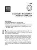
time (that is, modeling the objects in motion). Figure 9-1 shows how all the other diagrams
support the Class diagram.
Figure 9-1 All diagrams support the Class diagram.
Use Case
Model
Object
Diagram
Sequence
Diagram
Collaboration
Diagram
Activity
Diagram
Statechart
Diagram
Class
Diagram
154910-3 Ch09.F 5/31/02 2:05 PM Page 94
Session 9—Modeling the Static View: The Class Diagram 95
Although other diagrams are necessary, remember that their primary purpose is to sup-
port the construction and testing of the Class diagram. Whenever another diagram reveals
new or modified information about a class, the Class diagram must be updated to include
the new information. If this new information is not passed on to the Class diagram, it will
not be reflected in your code.
The Object diagram
¼
The class defines the rules; the objects express the facts.
¼
The class defines what can be; the object describes what is.
If the Class diagram says, “This is the way things should be,” but the Object diagram graphi-
cally demonstrates that “it just ain’t so,” then you have a very specific problem to track
down. The reverse is true, too. The Object diagram can confirm that everything is working
as it should. Session 13 walks you through an example of applying the Object diagram for
just this purpose.
Elements of the Class Definition
The class symbol is comprised of three compartments (rectangular spaces) that contain dis-
tinct information needed to describe the properties of a single type of object.
¼
The name compartment uniquely defines a class (a type of object) within a package.
Consequently, classes may have the same name if they reside in different packages.
¼
The attribute compartment contains all the data definitions.
¼
The operations compartment contains a definition for each behavior supported by
this type of object.
Technically, the UML allows for user-defined compartments as well as the
three standard ones, but I’ll leave that as an advanced topic for another book
or for your own personal study of the UML specification.
Sessions 10 and 11 present the rest of the notations that make up the Class diagram.
Modeling an Attribute
An attribute describes a piece of information that an object owns or knows about itself. To
use that information, you must assign a name and then specify the kind of information, or
data type. Data types may be primitive data types supplied by a language, or abstract data
types (types defined by the developer). In addition, each attribute may have rules con-
straining the values assigned to it. Often a default value helps to ensure that the attribute
always contains valid, meaningful data.
Tip
154910-3 Ch09.F 5/31/02 2:05 PM Page 95
Saturday Morning96
Attribute visibility
Each attribute definition must also specify what other objects are allowed to see the
attribute — that is its visibility. Visibility is defined as follows:
¼
Public (+) visibility allows access to objects of all other classes.
¼
Private (-) visibility limits access to within the class itself. For example, only
operations of the class have access to a private attribute.
¼
Protected (#) visibility allows access by subclasses. In the case of generalizations
(inheritance), subclasses must have access to the attributes and operations of the
superclass or they cannot be inherited.
¼
Package (~) visibility allows access to other objects in the same package.
Note the symbols for each type of visibility. The symbols provide a convenient shorthand
and tend to be used instead of the full name.
The rules for protected visibility vary a little among programming languages.
Check the rules for your particular implementation environment. For exam-
ple, protected in Java allows objects of classes within the same package to
see the value as well.
Given these requirements, the following notation is a common way of defining an
attribute:
visibility / attribute name : data type = default value {constraints}
Writing this down as a kind of cheat sheet isn’t a bad idea. It will help you remember all
the issues you need to address when defining data. Here’s the run-down on each element in
this expression.
¼
Visibility (+, -, #, ~): Required before code generation. The programming language
will typically specify the valid options. The minus sign represents the visibility “pri-
vate” meaning only members of the class that defines the attribute may see the
attribute.
¼
Slash (/): The derived attribute indicator is optional. Derived values may be com-
puted or figured out using other data and a set of rules or formulas. Consequently,
there are more design decisions that need to be addressed regarding the handling
of this data. Often this flag is used as a placeholder until the design decisions
resolve the handling of the data.
¼
Attribute name: Required. Must be unique within the class.
¼
Data type: Required. This is a big subject. During analysis, the data type should
reflect how the client sees the data. You could think of this as the external view.
During design, the data type will need to represent the programming language data
type for the environment in which the class will be coded. These two pieces of
information can give the programmer some very specific insights for the coding
of
get
and
set
methods to support access to the attribute value.
¼
Assignment operator and default value: Optional. Default values serve two valu-
able purposes. First, default values can provide significant ease-of-use improvements
for the client. Second and more importantly, they protect the integrity of the sys-
tem from being corrupted by missing or invalid values. A common example is the
Tip
154910-3 Ch09.F 5/31/02 2:05 PM Page 96
Session 9—Modeling the Static View: The Class Diagram 97
tendency to let numeric attributes default to zero. If the application ever attempts
to divide using this value, you will have to handle resulting errors that could have
been avoided easily with the use of a default.
¼
Constraints: Constraints express all the rules required to guarantee the integrity of
this piece of information. Any time another object tries to alter the attribute value,
it must pass the rules established in the constraints. The constraints are typically
implemented/enforced in any method that attempts to set the attribute value.
The constraint notation brackets appear throughout UML diagrams to iden-
tify any and all additional information that helps clarify the intent of the
modeling element. Place any text in the constraint brackets that is required
to explain the limitations to be imposed on the implementation of the mod-
eling element.
¼
Class level attribute (underlined attribute declaration): Optional. Denotes that
all objects of the class share a single value for the attribute. (This is called a static
value in Java.)
Creating an attribute specification
Table 9-1 shows you how to create a sample attribute definition for a company name. The
field has to handle characters and punctuation marks commonly found in company names,
but you’re limited to 30 positions. There is a no default value, but you want valid display
data, so you must initialize the field to spaces.
Table 9-1 Creating an Attribute Specification
Attribute Element Description Attribute Element Example
Create an attribute name company
Add the attribute data type company:character
Add the attribute’s default value, if any company:character = spaces
Set the constraints on the attribute value. For company:character = spaces {1 to 30
this example, first identify the field length. characters}
Next identify the types of data that can be used company:character = spaces {1 to 30
in the attribute. Add this information within characters including alphabetic,
the brackets. spaces, and punctuation characters;
no special characters allowed}
Set the attribute visibility (designate private - company:character = spaces {1 to 30
visibility with a minus (-) sign in front of characters including alphabetic, spaces,
the attribute). and punctuation characters; no special
characters allowed}
Note
154910-3 Ch09.F 5/31/02 2:05 PM Page 97
Saturday Morning98
In a modeling tool, an attribute definition may appear as a set of fields on a specifica-
tion window, or the single line format, or a combination of the two. Regardless of the tool
interface, this set of fields can be a good tool for remembering the types of questions you
need to answer for each piece of information in your model. This data forms the foundation
for your databases, your user interfaces, reporting, and nearly every aspect of your design.
Thoroughness here pays big dividends later.
Modeling an Operation
Objects have behaviors, things they can do and things that can be done to them. These
behaviors are modeled as operations. By way of clarification, the UML distinguishes between
operation and method, whereas many people use them interchangeably. In the UML, an
operation is the declaration of the signature or interface, the minimum information
required to invoke the behavior on an object. A method is the implementation of an opera-
tion and must conform to the signature of the operation that it implements.
Elements of an operation specification
Operations require a name, arguments, and sometimes a return. Arguments, or input para-
meters, are simply attributes, so they are specified using the attribute notation (name, data
type, constraints, and default), although it is very common to use the abbreviated form of
name and data type only.
Note that if you use constraints on an argument, you are constraining the input value,
not the value of the attribute as it resides in the source object. The value in the source
object was constrained in the attribute definition within the class.
The return is an attribute data type. You can specify the visibility of the operation:
private (-) limits access to objects of the same class, public (+) allows access by any object,
protected (#) limits access to objects of subclasses within the inheritance hierarchy (and
sometimes the same package), and package (~) limits access to objects within the same
package. Given these requirements, the following notation is used to define an operation:
visibility operationName ( argname : data type {constraints}, ) :
return data type {constraints}
Once again, writing this down as a kind of cheat sheet isn’t a bad idea. It will help you
remember all the issues you need to address when defining operations. Here’s the run-down
on each element in this expression.
¼
Operation name: Required. Does not have to be unique, but the combination of
name and parameters does need to be unique within a class.
¼
Arguments/parameters: Any number of arguments is allowed. Each argument
requires an identifier and a data type. Constraints may be used to define the valid
set of values that may be passed in the argument. But constraints are not supported
in many tools and will not be reflected in the code for the operation, at least not at
this point.
154910-3 Ch09.F 5/31/02 2:05 PM Page 98
Session 9—Modeling the Static View: The Class Diagram 99
¼
Return data type: Required for a return value, but return values are optional. The
UML only allows for the type, not the name, which is consistent with most program-
ming languages. There may only be one return data type, which again is consistent
with most programming languages.
¼
Visibility (+, -, #, ~): Required before code generation. The visibility values are
defined by the programming language, but typically include public (+), private (-),
protected (#), and package (~).
¼
Class level operation (underlined operation declaration): Optional. Denoted as
an operation accessible at the class level; requires an instance (object) reference.
¼
Argument name: Required for each parameter, but parameters are optional. Any
number of arguments is allowed.
¼
Argument data type: Required for each parameter, but parameters are optional.
¼
Constraints: Optional. In general, constraints express rules that must be enforced
in the execution of the operation. In the case of parameters, they express criteria
that the values must satisfy before they may be used by the operation. You can
think of them as operation level pre-conditions.
Creating an operation specification
Table 9-2 shows you how to create a sample operation to determine the total amount due on
an order. The total is the sum of all line items less the volume discount. Each line item
amount is the product of the unit price and discount. You need the answer back as a dollar
amount.
Table 9-2 Creating an Operation Specification
Operation Element Description Operation Element Example
Name the operation. totalOrderAmount
Define the arguments/parameters:
All the input information is on the Order object, totalOrderAmount (order : Order)
so an instance of Order is the only argument.
Name the argument and data type and separate
them with a colon. Try to use argument names
that match the argument type; this makes
referring to the value within the method
easier. The data type in this example is the
user-defined class “Order.” Enclose the
arguments in parentheses.
Continued
154910-3 Ch09.F 5/31/02 2:05 PM Page 99
Saturday Morning100
Table 9-2 Continued
Define the return data type:
The result returned by the operation must totalOrderAmount (order : Order) :
be a dollar amount, simply a number with Dollar
two decimal positions. Often we create a user-
defined data type (or abstract data type) to
contain dollar values. Place a colon and the
return data type after the arguments.
Identify and describe any constraints: totalOrderAmount (order : Order) :
You can use the all-purpose constraint Dollar {The total is the sum of all line
notation {} to hold the text that describes items less the volume discount. Each
the computation. line item is the product of the unit
As an alternative, you can put the rule in price and quantity.}
the data dictionary under the derived
attribute “total_order_amount.”
Set the visibility of the operation:
The UML notation for public is a plus (+) sign. + totalOrderAmount (order : Order) :
Dollar {The total is the sum of all line
items less the volume discount. Each
line item is the product of the unit price
and quantity.}
Modeling the Class Compartments
Now you need to put all this together in a class symbol. The class notation consists of the
three compartments mentioned earlier. You’ve just seen the contents of the second and
third compartments for attributes and operations, respectively. The first compartment —
the name compartment — gives the class its identity.
Figure 9-2 shows a UML class symbol with all three compartments and all the elements
needed to define a class with UML notation. The text addresses each compartment of the
class and refers back to Figure 9-2.
154910-3 Ch09.F 5/31/02 2:05 PM Page 100
Session 9—Modeling the Static View: The Class Diagram 101
Figure 9-2 Complete class specification with all three compartments
Name compartment
In Figure 9-2, the name compartment occupies the top section of the class box. The name
compartment holds the class name, an optional stereotype, and optional properties. The
name is located in the center of the compartment. The stereotype (<< >>) may be used to
limit the role of the class in the model and is placed at the top of the compartment.
Common examples of class stereotypes include
<<Factory>>
, based on the Factory design
pattern, and
<<Interface>>
, for Java interfaces or for user interfaces.
Properties use the constraint notation { } and are placed in the bottom-right corner of
the compartment. Properties are basically constraints used to clarify the intent in defining
the model element. Properties can be used to document the status of a class under develop-
ment or for designations such as abstract and concrete.
Attribute compartment
In Figure 9-2, the attribute compartment occupies the middle section of the class box.
The attribute compartment simply lists the attribute specifications for the class using the
notation presented earlier in “Modeling an Attribute.” The order of the attributes does not
matter.
<<User>>
Customer
- name: String = blank
- mailingaddress: Address = null
- /accountbalance: Dollar = 0
- customerid: integer = none {assigned by system}
+ getName (): String
+ setName (name: String)
+ setAccountBalance (amount: Dollar)
+ getAccountBalance (): Dollar
+ setMailingAddress (street1: String, street2: String,
city: String, state: State, zipcode: integer)
{last updated 12-15-01}
154910-3 Ch09.F 5/31/02 2:05 PM Page 101
Saturday Morning102
Operation compartment
In Figure 9-2, the operations compartment occupies the bottom section of the class box.
Operations are simply listed in the operation compartment using the notation presented in
“Modeling an Operation.” The order does not matter. The operation compartment is placed
below the name compartment, and below the attribute compartment when all compartments
are visible.
Creating Different Views of a Class
The completed class definition can be shown with all three compartments visible or as just
the name compartment. This form is often used in the early stages of analysis when the
focus is on object definitions and relationships. As more information is discovered about the
attributes and operations, the other two compartments can be revealed as well.
Some tools also give the option to show some or all of the operation specifications. For
example, one view may show only the operation names. Another view may reveal the names
and the arguments, while yet another may show the entire signature with argument data
types and return data types. Figure 9-3 illustrates two ways of drawing the class symbol.
This facility helps focus evaluation of the diagram to the interests of the audience.
Figure 9-3 Alternative views of a class symbol for different audiences and purposes
REVIEW
The Class diagram is the primary diagram for code generation and for reverse engineering.
Consequently, it tends to be the focus of most modeling efforts, with all the other diagrams
playing a supporting role. The term object model is actually a reference to two diagrams, the
Class diagram and the Object diagram, although when the term is used it most often refers
to a Class diagram.
¼
The Class diagram represents all the rules regarding the construction and use of
objects. The Object diagram describes the facts about objects that actually exist.
Consequently, the Object diagram provides a valuable testing tool to verify the Class
diagram.
<<User>>
Customer
- name: String = blank
- mailingaddress: Address = null
- /accountbalance: Dollar = 0
- customerid: integer = none {assigned by system}
+ getName (): String
+ setName (name: String)
+ setAccountBalance (amount: Dollar)
+ getAccountBalance (): Dollar
+ setMailingAddress(street1: String, street2: String,
city: String, state: State, zipcode: integer)
{last updated 12-15-01}
<<User>>
Customer
{last updated 12-15-01}
<<User>>
Customer
{last updated 12-15-01}
154910-3 Ch09.F 5/31/02 2:05 PM Page 102
Session 9—Modeling the Static View: The Class Diagram 103
¼
The class symbol consists of three compartments: the name compartment, the
attribute compartment, and the operations compartment. The UML supports the defi-
nition of additional compartments. The UML also supports a number of views of the
class that allow the analyst to focus attention on particular features of the class.
¼
Attributes must be specified with all the information needed to protect the
integrity of the data they describe. To do so, the attribute declaration includes visi-
bility, a unique name (within the class), a data type, possibly a default value, possi-
bly constraints, and, when appropriate, a class-level designation.
¼
Operations must be specified with all the information needed to guarantee the proper
use and execution of the behavior. To do so, the operation declaration includes visibil-
ity, a name, the list of arguments/parameters and their required data types, a return
data type when needed, and, when appropriate, a class-level designation.
QUIZ YOURSELF
1. What diagram is used to generate code? (See “The Object Model.”)
2. What are the three parts of a class in a UML class symbol? (See “Elements of the
Class Definition.”)
3. How do you fully define an attribute? (See “Modeling an Attribute.”)
4. Name two ways to use the Object diagram. (See “The Object diagram.”)
5. What element defines the level of access that is required by an operation? (See
“Elements of an operation specification.”)
154910-3 Ch09.F 5/31/02 2:05 PM Page 103
154910-3 Ch09.F 5/31/02 2:05 PM Page 104
Session Checklist
✔
Explaining and illustrating the basic notation for all associations
✔
Explaining and illustrating the notations for association classes,
reflexive associations, and qualified associations
A
ssociations between objects are similar to associations between people. In order for
me to work with you, I need to communicate with you. This requires that I have
some way to contact you, such as a phone number or an e-mail address. Further, it is
often necessary to identify why we are associated in order to clarify why we do and do not
participate in certain kinds of communication. For example, if we are associated because
you are a programmer and I am a database administrator, we probably will not discuss
employee benefits as part of our duties.
There would also probably be some limitations placed on our interactions:
¼
We would want to limit the number of participants in the relationship to ensure
efficiency.
¼
We would want to check the qualifications of the participants to ensure we have the
right participants.
¼
We would want to define the roles of the participants so that everyone knows how
to behave.
All these requirements apply equally to objects. The UML provides notations to address
them all. I’ll start with the basics and then add a few twists.
SESSION
The Class Diagram: Associations
10
16910-3 Ch10.F 5/31/02 2:05 PM Page 105
Saturday Morning106
Modeling Basic Association Notations
The following notations appear on almost every association you will model. Most of these
elements are similar to those you find in data modeling or database design. In fact, most of
the concepts come from these fields. The concepts worked well in data modeling, so they
were simply brought forward into object modeling as a form of “best practices.” I suggest
you memorize them because you will spend a lot of time working with them.
Association name
The purpose of the association can be expressed in a name, a verb or verb phrase that
describes how objects of one type (class) relate to objects of another type (class). For exam-
ple, a person owns a car, a person drives a car, and a person rents a car. Even though the
participants are the same in each association, the purpose of each association is unique,
and as such they imply different rules and interactions.
To draw the UML associations for these three examples, you need to start with four basic
elements.
¼
The participating classes, Person and Car. In this session I show only the name com-
partment so that your attention remains focused on the classes and their associations.
¼
The association, represented by a line between the two classes (pretty technical
huh?).
¼
The name of the association, represented by a verb or verb phrase on the associa-
tion line. Don’t worry about the exact position of the name. As long as the name
appears somewhere in the middle of the line, you’re okay. Just leave room at both
ends of the association for all the other things you’ll learn about later in this
session.
¼
The direction to read the name (indicating the direction is optional).
The first two examples in Figure 10-1 read pretty much the way I described them in the
text — Person owns Car and Person drives Car. Note that if these two statements are true,
then the reverse would be equally true — Car is owned by Person and Car is driven by
Person. Associations may be read in both directions as long as you remember to reverse the
meaning of the association name from active to passive.
But in the third example in Figure 10-1, the association name would not make sense if you
read it in the typical left to right fashion —Car rents Person. This is a case where the direc-
tion indicator is particularly appropriate, even required, to make sense of the association by
reversing the normal reading order so that it reads from right to left — Person rents Car.
16910-3 Ch10.F 5/31/02 2:05 PM Page 106
Session 10—The Class Diagram: Associations 107
Figure 10-1 Directional notation for association names
Remember the direction indicator when you’re making a lot of changes to a
diagram where you have to rearrange the classes. It is easy for classes to
reverse position on the diagram, resulting in nonsensical association names.
The indicators can prevent unnecessary confusion.
Association multiplicity
The UML allows you to handle some other important questions about associations: “How
many Cars may a Person own?” “How many can they rent?” “How many people can drive a
given Car?” Associations define the rules for how objects in each class may be related. So
how do you specify exactly how many objects may participate in the relationship?
Multiplicity is the UML term for the rule that defines the number of participating objects.
A multiplicity value must be assigned to each of the participating classes in an association.
As illustrated in Figure 10-2, you need to ask two separate questions.
Figure 10-2 Assigning multiplicity to each end of an association
Person
How many
People own
each Car?
How many Cars
are owned
by each Person?
Owns Car
Tip
Person Owns Car
Person Drives Car
Car Rents Person
16910-3 Ch10.F 5/31/02 2:05 PM Page 107
Saturday Morning108
The answer to each question goes next to the class that describes the objects that the
question is counting. The answer to “How many People . . .” goes on the end of the associa-
tion near the Person class. The answer to “How many Cars . . .” goes on the end of the asso-
ciation next to the Car class.
Multiplicity is expressed in a couple of ways. The most common is a range defining the
minimum number of objects allowed and the maximum number of objects allowed in the
format
Minimum . . Maximum
You must use integer values for the minimum and maximum. But, as you have probably
found in your own applications, sometimes you don’t know the upper limit or there is no
actual upper limit. The UML suggests the use of an asterisk to mean no upper limit. Used by
itself, the asterisk can also mean the minimum is zero and there is no upper limit, or zero
or more.
You may also encounter a situation when a range is not appropriate. If you had to define
how many cylinders are in the engines you service, you might want to say, “I only work on
4–, 6–, and 8-cylinder engines.” For these situations, the UML suggests a comma-separated
list (for example, 4,6,8).
You can simplify the notation when the minimum and maximum values are the same by
using a single value. So instead of writing 4 4, you can just write 4. This is a nice shortcut,
but beware! The most common place to use this shortcut is when the multiplicity is 1 1.
Unfortunately, the shortcut encourages people to overlook or ignore the possibility that the
minimum is zero, that is, the relationship is optional.
I’ll use the example of a car and an engine. That’s easy! Each car has one engine, right?
Well, what about cars on an assembly line? During the first n stages of assembly, there is no
engine in the car. In this case, the multiplicity should be 0 1 to allow the car to exist
before it has an engine installed. Frankly, I have found very few instances when the mini-
mum multiplicity should be 1. My rule of thumb is to set the minimum to 0 until I have
positive proof that the one object cannot exist with the other object.
Most software failures are because of small, difficult-to-find errors like the
difference between 0 and 1. Most of those errors are caused by assumptions
or failures to think critically about the details. I once witnessed an explo-
sion in a power plant caused by a one-character mistake in a program. Like
they say, “The devil is in the details.”
Here’s a summary list of the options for specifying multiplicity followed by some
examples.
¼
Values separated by two periods ( ) mean a range. For example, 1 3 means between
1 and 3 inclusively; 5 10 means between 5 and 10 inclusively.
¼
Values separated by commas mean an enumerated list of possibilities. For example,
4,6,8 means you may have 4 objects or 6 objects or 8 objects of this type in the
association.
¼
Asterisk (*) when used alone means zero or more, no lower or upper limit.
¼
Asterisk (*) when used in a range (1 *) means no upper limit — you must have at
least one but you can have as many more as you want.
Tip
16910-3 Ch10.F 5/31/02 2:05 PM Page 108
Session 10—The Class Diagram: Associations 109
Association roles
Sometimes the association name is a bit hard to determine. For example, what English word
could you use for the association name between parents and children? The UML provides an
alternative that may be used in place of the name or along with it to help make the reason
for the association as clear as possible. This alternative is called a role because it describes
how an object participates in the association.
For example, many employees contribute to a project. But you know from experience that
they participate in different ways. Figure 10-3 shows how you can draw multiple associa-
tions and label them to differentiate the types of participation. Each role is placed at the
end of the association next to the type of object that plays the role. You may use them on
one, both, or neither end of each association.
Figure 10-3 Role names on an association
There is one other thing worth noting about roles and names. Role names generate code.
Association names do not generate code. The role name can be used to name the attribute
that holds the reference to the object that plays the role. In Figure 10-3, the
Project
object could have an attribute named
programmer
that holds a reference to an
Employee
object that plays the role of programmer, and another attribute called
projectlead
that
holds reference to another
Employee
object that plays the role of project lead.
Association constraints
Constraints appear throughout the UML notation. You used them in Session 9 when you
declared attributes and operations. Constraints fulfill much the same function for associa-
tions. First take a look at Figure 10-4, in which no constraints are specified.
Figure 10-4 An association without constraints
Drives
Person
1 1
0 *
Car
participates in
participates in
participates in
Employee
programmer
Project
projectlead
uidesigner
16910-3 Ch10.F 5/31/02 2:05 PM Page 109
Saturday Morning110
Is it really true that any Person object can drive a Car? Legally, only people with valid
driver’s licenses are allowed to drive. You can add this information to the model using a pair
of curly braces {} containing the text that describes the rule you want to enforce (for exam-
ple, {must have a valid driver’s license}). In Figure 10-5, you place the constraint at the end
of the association near Person, the type of object that must conform to the rule before it
can participate in the relationship.
Figure 10-5 An association with a constraint on the Person objects’ participation
Constraints may appear on both ends, either ends, or neither end of the association. It
really depends on the problem you’re trying to describe. Don’t worry too much about place-
ment. You can place the constraint anywhere near the end of the association.
But what if there is more than one constraint? Simple. Just add more text between the
braces. Don’t create more braces.
The UML also defines a constraint language for a more rigorous constraint
specification. For more information, check out UML 1.4 chapter 6 Object
Constraint Language (OCL) Specification.
Modeling Extended Association Notations
Now that you have the basics down, you’re ready for a few, more-exotic concepts. Actually,
some or all of these concepts may be familiar to you from database design or personal pro-
gramming experience.
Association class
An association class encapsulates information about an association. Let me say that again,
because this one often proves difficult to understand. An association class encapsulates
information about an association.
In Figure 10-6, you know that Customers order Products. But when customers order prod-
ucts there is usually more that you need to know, like when did they order the products?
How many did they order? What were the terms of the sale? All the answers to these ques-
tions are simply data. All data in an object-oriented system must be contained in (encapsu-
lated in) an object. There must be a class to define each type of object. So, define all this
data in a class. Then to show that the data describes the association, attach the new class
to the association with a dashed line.
Tip
Drives
Person
{must have valid driver's license}
1 1 0 *
Car
16910-3 Ch10.F 5/31/02 2:05 PM Page 110
Session 10—The Class Diagram: Associations 111
Figure 10-6 Association class notation
Be on the lookout for association classes when you see a multiplicity of
more than one on both ends of the association. You don’t always need an
association class on these many-to-many associations, but it is a common
place to find them.
Reflexive association
Reflexive association is a fancy expression that says objects in the same class can be related
to one another. The entire association notation you’ve learned so far remains exactly the
same, except that both ends of the association line point to the same class. This is where
the reflexive association gets its name. The association line leaves a class and reflects back
onto the same class.
Both examples in Figure 10-7 are equivalent expressions. The only difference is that one
uses roles and the other uses an association name.
Figure 10-7 Two ways to model a reflexive association
A reflexive association is a very common way to express hierarchies. The example in
Figure 10-7 models a hierarchical reporting structure. I could use the same technique for
companies owned by other companies.
Qualified association
Qualified associations provide approximately the same functionality as indexes, but the
notation has a bit of a twist. To indicate that a customer can look up an order using the
order’s ordernumber attribute, place the ordernumber attribute name and data type in a rec-
tangular box on the Customer end of the association. The rest of the association notation
remains intact but is pushed out to the edge of the rectangle.
Employee
0 1
0 *
Using role names
supervisor
subordinate
Employee
0 1
0 *
Using an association name
supervises
Tip
orders
Customer
0 *0 *
Product
Order
- quantity: integer = 0
- orderdate: Date = today
- terms: Terms = null
16910-3 Ch10.F 5/31/02 2:05 PM Page 111
Saturday Morning112
The placement of the qualifier is sometimes confusing. The best way I have found to
remember it is to think of it like this (refer to Figure 10-8):
“The Customer uses the ordernbr to look up an Order.”
or
“One type of object uses the qualifier to access the other (qualified) type of
object.”
The qualifier goes next to the class of objects that will use the value to do the look up. It
is not exactly intuitive but it works.
Figure 10-8 Qualified association
Typically the qualifier is an attribute of the class on the opposite end of the
association, so make certain that the two names and data types agree.
Use qualifiers to reduce the multiplicity in the same way you would use indexes in a
database to reduce the search time for a specific row or subset of rows. For example, in
Figure 10-8, note how the multiplicity for the Order end of the association changed from
0 * to 1 1. This is because the qualifier provided a unique key for Order objects. Before the
qualifier was established, navigation across the association would result in a list of all
orders associated with that Customer, because the Customer relationship was the only refer-
ence available to select the Orders.
REVIEW
Associations define how objects will be allowed to work together.
¼
An association is named to describe the purpose of the relationship.
¼
Role names may be used with or in place of the association name to describe how
the objects participate in the relationship.
Tip
places
Customer
0 *1 1
Order
Without a qualifier
places
Customer
1 1 1 1
Order
- ordernbr: integer
- quantity: integer = 0
- orderdate: Date = today
With a qualifier
ordernbr: integer
16910-3 Ch10.F 5/31/02 2:05 PM Page 112
Session 10—The Class Diagram: Associations 113
¼
Multiplicity defines the number of objects that may participate. Ranges are specified
as minimum value maximum value. When the minimum and maximum are the same,
you may simplify the range to a single value (but watch out!). A comma-separated
list represents an enumeration of options. An asterisk may be used to indicate that
there is no defined upper limit to the number of objects. By itself, an asterisk
means zero or more objects.
¼
Constraints are rules that must be enforced to ensure the integrity of the relation-
ship. The constraints may be placed on each end of the association. Constraints are
always enclosed in a single pair of curly braces {}.
¼
An association class encapsulates information about an association. The most com-
mon types of data include when the relationship began, when it ended, and the
current state of the relationship. But there can be any number of data items. Apart
from its origin, an association class is a class like any other class.
¼
The phrase reflexive association describes an association in which all the participat-
ing objects are of the same type (class). The association line goes out of a class and
turns right back to the same class so that both ends of the association touch the
same class. All the other notations and rules for defining associations apply to
reflexive associations. One of the most common uses for reflexive associations is for
defining hierarchies.
¼
Qualified associations simplify the navigation across complex associations by provid-
ing keys to narrow the selection of objects.
¼
All these notations may appear on the same diagram.
QUIZ YOURSELF
1. What should the association name describe? (See “Association name.”)
2. When would you want to use role names and where do you place them?
(See “Association roles.”)
3. What is a constraint? (See “Association constraints.”)
4. Where do you most often find opportunities to use an association class?
(See “Association class.”)
5. Why would you use a qualified association? (See “Qualified association.”)
16910-3 Ch10.F 5/31/02 2:05 PM Page 113
PART
#
PART
Saturday Morning
Part Review
II
1. What is the relationship between people and roles in a Use Case diagram?
2. Where do you use associations in a Use Case diagram?
3. Why would you use the
<<include>>
dependency stereotype?
4. When would you use the
<<extend>>
dependency stereotype?
5. Where can you use the generalization relationship on a Use Case diagram?
6. Why is it so important to set the context of the system first?
7. How do you find associations?
8. How do you model the fact that one Use Case always uses the help of another Use
Case?
9. How do you model the fact that one Use Case sometimes uses the help of another
Use Case, but only under a specified condition?
10. How do you know that you can use generalization?
11. What is the purpose of defining the Use Case initiation?
12. What is the fundamental difference between assumptions and pre-conditions?
13. What is the Use Case dialog?
14. Why do we define the termination options separately from the dialog?
15. How do you know how detailed the dialog should be?
16. What is the relationship between a Use Case and a scenario?
17. Why are scenarios important to a project?
18. What two sources can you use to find scenarios?
19. How should you handle segments of logic that are repeated, as in loops?
20. How can you apply scenarios to aid in the quality of your project?
21. What is the primary difference between the Class diagram and the Object diagram?
22. What does a constraint mean in an attribute specification?
23. What does a constraint mean in an operation specification?
174910-3 PR02.F 5/31/02 2:05 PM Page 114
24. What appears in the name compartment of a class?
25. Do you always have to display all the information about a class?
26. What should the association name describe?
27. When would you want to use role names and where do you place them?
28. What is a constraint?
29. Where do you most often find opportunities to use an association class?
30. Why would you use a qualified association?
Part II — Saturday Morning Part Review 115
174910-3 PR02.F 5/31/02 2:05 PM Page 115
PART
Saturday
Afternoon
III
Session 11
The Class Diagram: Aggregation and
Generalization
Session 12
Applying the Class Diagram to the Case
Study
Session 13
Modeling the Static View: The Object
Diagram
Session 14
Modeling the Functional View: The
Activity Diagram
Session 15
Applying the Activity Diagram to the Case
Study
Session 16
Modeling the Dynamic View: The
Sequence Diagram
184910-3 Pt03.F 5/31/02 2:05 PM Page 116
Session Checklist
✔
Explaining the concepts of aggregation and composition
✔
Illustrating the use of the notation for aggregation and composition
✔
Explaining the concepts of generalization and inheritance
✔
Illustrating the use of generalization
I
n Session 10, you learned about associations. An association describes a set of rules
regarding how objects may be related to one another. But associations can be a bit
more restrictive. In this session, I describe two common subtypes of association, called
aggregation and composition. Then I explain how you can refactor your design using gen-
eralization (inheritance).
Modeling Aggregation and Composition
Figure 11-1 outlines the relationships among the concepts of association, aggregation, and
composition.
Later in this session, I explain the contents of this graphic more fully. But right now I
want to make two points as clear and strong as possible:
¼
Every aggregation relationship is a type of association. So every aggregation relation-
ship has all the properties of an association relationship, plus some rules of its own.
¼
Every composition relationship is a form of aggregation. So every composition
relationship has all the properties of an aggregation, plus some rules of its own.
SESSION
The Class Diagram: Aggregation
and Generalization
11
194910-3 Ch11.F 5/31/02 2:05 PM Page 117
Saturday Afternoon118
Figure 11-1 The relationship between association, aggregation, and
composition
Elements of aggregation
Aggregation is a special type of association used to indicate that the participating objects
are not just independent objects that know about each other. Instead, they are assembled or
configured together to create a new, more complex object. For example, a number of differ-
ent parts are assembled to create a car, a boat, or a plane. You could even create a logical
assembly like a team where the parts are not physically connected to one another but they
still operate as a unit.
To model aggregation on a Class diagram:
1. Draw an association (a line) between the class that represents the member and the
class that represents the assembly or aggregation. In Figure 11-2, that would mean
a line between the Team class and the Player class.
2. Draw a diamond on the end of the association that is attached to the assembly or
aggregate class. In Figure 11-2, the diamond is next to the Team class that repre-
sents a group of players.
3. Assign the appropriate multiplicities to each end of the association, and add any
roles and/or constraints that may be needed to define the rules for the relation-
ship. Figure 11-2 shows that a Player may be a member of no more than one Team,
but a Player does not have to be on a Team all the time (0 1). The Team is always
comprised of exactly nine Players (9 9 or just 9). A Player is considered a member
(role name) of a Team. Every Player is constrained by the fact that she must have a
current contract in order to be a member of a Team.
Figure 11-2 How to represent an aggregation relationship in the UML
Team
0 1 9 9
Player
member
{must have a
current contract}
Association
Objects are aware of one another so they can work together
Aggregation
1. Protects the integrity of the configuration
2. Functions as a single unit
3. Control through one object – propagation downward
Composition
Each part may only be a member of one aggregate object
194910-3 Ch11.F 5/31/02 2:05 PM Page 118