UML WEEKEND CRASH COURSE phần 9 pptx
Bạn đang xem bản rút gọn của tài liệu. Xem và tải ngay bản đầy đủ của tài liệu tại đây (360.78 KB, 38 trang )
Sunday Afternoon280
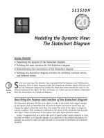
Figure 27-2 UML Sequence diagram, HTTP protocol
For example, if the URL entered is
www.nextstepeducation.com/index.html
, the
Web request will be sent to the Web server on the machine with a domain name of
www.
nextstepeducation.com
. When the Web server receives the request, it will create an HTTP
response, which is a packet of information that includes the requested document or error
message and other metadata about the response. The Web server will look for the file that
was specified in the URL. In the example in Figure 27-2, the Web server will load the
index.html file and place the contents of that file into the HTTP response. The Web server
will then send the HTTP response back across the network to the Web browser that made
the request. The Web browser will take the HTML out of the HTTP response, interpret it, and
display the content with the specified formatting.
Some people may question the choice of “objects” in the Sequence diagram
in Figure 27-2. In truth, a Web browser is simply a larger, more complex
object than a customer or an order. This approach is common practice when
modeling interaction between systems (that is, when modeling the systems
as objects).
Dynamic Web Content
The previous section showed how HTTP is used to send static HTML content to Web
browsers. Most Web applications require dynamically generated content. For example, when
you go to a weather forecast Web site, you don’t want it to give you the contents of an
HTML file that was saved a month ago; you want it to generate an up-to-date weather fore-
cast for you on the spot and return it to you. Furthermore, you want to be able to access
weather information for a certain city. Thus, there must be some programming logic that
can take your user input and adapt the result to your request. So a weather Web site would
Tip
<<Actor>>
:User
:Web Browser
create HTTP request
type URL
send HTTP request
:Web Server
interpret and display HTML
create HTTP response
send HTTP response
copy contents of requested
HTML file into HTTP response
424910-3 Ch27.F 5/31/02 2:19 PM Page 280
Session 27—Introduction to Web Development with Java 281
need to have some programming logic that generated the HTML for the HTTP response. The
same is true of any e-commerce site where you want to be able to do activities such as
search for items, place items in a shopping cart, or make purchases. All those activities
require some code on the Web server that reacts to the HTTP request by completing some
processing and then returning Web content such as HTML or XML. In reality, almost all
modern Web sites include at least a few pages of dynamically generated content.
Consider further how a weather Web site might be implemented. For a moment, if you
ignore the Web aspect of this system, imagine how you could write code in almost any pro-
gramming language to query a database or other information source to gather data on the
weather, calculate statistics, generate weather map images, and produce HTML of the
results. The only problems that need to be solved are to find a way to trigger that code with
an HTTP request arriving at the Web server, and then to have the HTML results placed in an
HTTP response and have the HTTP response sent to the Web browser. CGI scripts and Java
servlets are two technologies that solve this problem by hooking your code into the HTTP
Web protocol.
This general solution is shown in the UML Deployment diagram in Figure 27-3. The dia-
gram refers to your weather reporting code as the Web application code. This code that you
have written is just normal code that can do almost any of the normal things you can do in
that language, usually including talking to resources such as databases, making calcula-
tions, sending e-mails, and outputting HTML, which is included in the HTTP response. You
place this code on the Web server and map it to a particular URL. The HTTP protocol will be
used in the same way that it was for static content: The Web browser generates an HTTP
request object corresponding to the URL entered by the user, and sends that HTTP request
to the Web server. The Web server recognizes that this URL was mapped to your Web appli-
cation code and calls your code to go gather the data and output the Web content into the
HTTP response, which is sent back to the Web browser.
Figure 27-3 UML Deployment diagram for dynamic Web content
CGI Scripts were the original solution to the problem of generating dynamic Web content.
They allow you to write scripts in a wide variety of languages, including Perl and C. They then
provide the mechanism for hooking your script into the HTTP request/response mechanism.
CGI Scripts were very commonly used and are still used frequently, although they are gradu-
ally being used less in favor of a variety of newer solutions I discuss in the next section.
Java servlets
Java servlets provide the same basic functionality as CGI scripts. They allow you to write
a class in Java that will generate the dynamic Web content. Listing 27-2 shows how a
Web page that displays the current date could be created as a Java servlet. If you haven’t
Client
Web
Browser
Database Server
Database
Web Server
<<HTTP>>
Web
Server
Web
Application
Code
<<TCP>>
424910-3 Ch27.F 5/31/02 2:19 PM Page 281
Sunday Afternoon282
studied Java programming, this example may seem a bit confusing. But the important thing
to notice is not the syntax, but how the HTML is generated and placed into the HTTP
response (the HTML is the bold text in Listing 27-2). Notice that the servlet is a class and,
in this case, it only has one method, which is called
doGet
. The servlet container will call
this method to service the request whenever a Web browser sends an HTTP request for this
servlet. The
doGet
method always takes two parameters that represent the HTTP request
coming in and the HTTP response going out. The variable named
out
is a reference that
allows you to write content to the body of the HTTP response. Thus, all the HTML and other
content in the
out.println
method calls is placed into the HTTP response and sent by the
Web server back to the Web browser, which displays the HTML. In this case, the Web content
is almost all static content, except that it places “new java.util.Date()” into the output.
This puts the current date and time onto the Web page. Notice that all the handling of the
HTTP response and HTTP request is done behind the scenes. All you have to write is how
you want to service the request. Servicing the request could include querying or updating
databases, sending e-mails, calling legacy code in other languages using CORBA, or a wealth
of other activities that may be accomplished with Java.
Listing 27-2 Java Servlet
1 import javax.servlet.http.*;
2 import java.io.*;
3 import java.util.*;
4
5 public class DateServlet extends HttpServlet {
6 public void doGet(HttpServletRequest request,
7 HttpServletResponse response)
8 throws IOException {
9
10 response.setContentType(“text/html”);
11 PrintWriter out = response.getWriter();
12
13 out.println(“<html>”);
14 out.println(“<head>”);
15 out.println(“<title>Current Date and Time</title>”);
16 out.println(“</head>”);
17 out.println(“<body>”);
18 out.println(new Date());
19 out.println(“</body>”);
20 out.println(“</html>”);
21
22 out.close();
23 }
24}
Java servlets offer a powerful technology for developing dynamic Web content and
complete Web applications. Java servlets are simply regular Java classes that follow a few
special rules. As a result, servlets have all the traditional benefits of Java. These benefits
include cross-platform code that can run on any kind of computer with a Java Virtual
Machine (JVM), a fully object-oriented language, and massive libraries of pre-written code
to simplify tasks such as database access and remote method invocation.
424910-3 Ch27.F 5/31/02 2:19 PM Page 282
Session 27—Introduction to Web Development with Java 283
Despite frequent confusion, Java and JavaScript are very different technolo-
gies. JavaScript is a scripting language usually written alongside HTML and
executed in the Web browser. JavaScript can be useful for small tasks such as
validating form input before it is sent to the server. You could place JavaScript
inside of the out.println statements of the Java servlet, just as the HTML was
placed in those statements.
Template pages
There is one substantial problem with using servlets in the manner that I just showed.
When using servlets for producing Web content such as HTML, you have to place the HTML
inside the Java code. Whether you’re talking about HTML and Java, SQL and business logic
code, or almost any other combination of technologies, mixing different technologies
almost always leads to more complicated development and maintenance. It requires that the
developer and maintainer of that code be proficient in both technologies. It also means
that a change in one of the technologies impacts the other — a symptom of tight coupling,
which results in high maintenance costs. Thus, to achieve loose coupling and good main-
tainability, you should usually try to avoid mixing technologies.
This general principle is particularly true for HTML and Java. There are few people who
are both experienced programmers and talented Web content developers. Even if you hap-
pen to have both of these skills, developing Web content inside of programming code can
be difficult. In addition, maintenance is more difficult because changing the Web page lay-
out requires entering the Java files to change the HTML. CGI scripts have the same drawback
of mixing Web content with a programming language. So using servlets or CGI scripts to
generate Web content can be costly and awkward, and may lead to low cohesion.
Template pages are a major part of the solution to this development and maintenance
problem. Template page technologies such as JSP, ASP.NET, PHP, and Cold Fusion allow you
to mix code or special tags inside a markup language page, such as an HTML page.
JavaServer Pages
JavaServer Pages (JSPs) are Java’s version of template pages. Listing 27-3 shows a JSP that
will produce an identical Web page to the Java servlet in Listing 27-2.
Listing 27-3 JavaServer Page
<html>
<head>
<title>Current Date and Time</title>
</head>
<body>
<%=new java.util.Date()%>
</body>
</html>
If you glance too briefly at this JSP page, you may mistake it for an HTML page. In fact,
it is all HTML except for line 6, which is a line of Java code that inserts the current date
Note
424910-3 Ch27.F 5/31/02 2:19 PM Page 283
Sunday Afternoon284
and time. A JSP page is composed of your Web content, such as HTML, with Java code inter-
mixed to insert the dynamic content. Comparing the Java servlet in Listing 27-2 and the
JSP page in Listing 27-3, you can probably see why JSP code is usually far easier to write
and develop than a servlet for producing Web content. A JSP page generally has less compli-
cated Java logic, is usually easier to read, and is much easier to maintain. A JSP page also
doesn’t need to be compiled by the programmer and may be easier to deploy into the Web
server, which makes the development and maintenance process a bit simpler. Other template
page technologies like ASP, PHP, and Cold Fusion work in a similar way, although each has
its own specific features, advantages, and disadvantages.
It is worth noting that JavaServer Pages turn into servlets. The JSP container class auto-
matically writes a Java servlet much like the one in Listing 27-2 (although significantly
harder to read) that has the same functionality as the JSP page that you wrote. All requests
for your JSP page will actually be handled by the Java servlet that represents it. Thus, JSP
is simply an easy way to write a Java servlet without having to write as much Java code.
The UML state diagram in Figure 27-4 explains this. The programmer writes a JSP. At or
before the first request for that JSP, the JSP container automatically writes the servlet that
represents that JSP and compiles it. From this point on, the lifecycle of a JSP is the same as
a servlet. When a request comes in, the servlet will be instantiated and the same instance of
the servlet will be used for all requests until the JSP container decides that the servlet
should be unloaded, usually due to the container shutting down or a long period with no
requests for that JSP. If the programmer changes the JSP, that servlet will be permanently
unloaded and the lifecycle starts over with the new version of the JSP being translated.
Figure 27-4 UML state diagram, JSP Lifecycle
You may think that writing only JSPs, as opposed to writing servlets, would be easier,
but that isn’t actually the case. If you need to write a servlet or JSP that primarily gener-
ates Web content, then it will almost always be easier to write it as a JSP. If you need to
write a servlet or JSP that has a lot of logic and generates very little or no content, then it
will usually be easier to write it as a servlet.
JSP Page
JSP Container Translates JSP
Servlet Class
(Not Instantiated)
Servlet Class (Instantiated
and initialized)
JSP Container Unloads JSP
HTTP Request Received/Request Serviced
HTTP Request Received
JSP Written By Programmer
Final
State
JSP Removed Or Modified
424910-3 Ch27.F 5/31/02 2:19 PM Page 284
Session 27—Introduction to Web Development with Java 285
REVIEW
The UML is a useful tool for modeling Web systems. The UML was not designed for the
purpose of modeling Web systems, so some adaptations must be made.
¼
Non–object-oriented technologies are often viewed as objects in order to demonstrate
their characteristics and behaviors in Class, Sequence, and Collaboration diagrams.
Non–object-oriented hierarchies such as XML may be mapped to class hierarchies in a
Class diagram to represent their structure.
¼
Sequence or Collaboration diagrams can model the interactions of architecture ele-
ments like Web browsers, Web applications, and HTML pages. Component diagrams
are frequently used to show how mixed technologies are integrated.
¼
Component diagrams can model the relationships between the architecture elements.
¼
Deployment diagrams are frequently used to show the network aspects of a Web
system.
¼
The basic Web architecture is based on a request/response protocol called HyperText
Transfer Protocol (HTTP). Web browsers make HTTP requests to Web servers, which
generate or load Web content such as HTML and return it to the Web browser. This
communication is often modeled using a Sequence or Collaboration diagram.
¼
CGI scripts, Java servlets, and JavaServer Pages (JSP) are just a few of the wide vari-
ety of technologies that you can use to dynamically generate Web content. Both
Java servlets and JSPs provide the power and flexibility of the Java language for
dynamic Web development. JSPs are easier to code, debug, and maintain for pages
that are exclusively or primarily producing Web content. Java servlets are easier to
code, debug, and maintain when they are generating little or no Web content.
QUIZ YOURSELF
1. What makes modeling a Web application in UML different from modeling a non-
Web application? (See “Issues in Using the UML in Web Development.”)
2. What UML diagram could you use to model the communication between a Web
browser and a Web server? (See “Basic Web Architecture and Static Web Content.”)
3. What UML diagram would you use to model the lifecycle of a JSP? (See “JavaServer
Pages.”)
4. What UML diagram could you use to model how components of your system are
deployed on the client machine and on the Web server? (See “Dynamic Web
Content.”)
424910-3 Ch27.F 5/31/02 2:19 PM Page 285
424910-3 Ch27.F 5/31/02 2:19 PM Page 286
Session Checklist
✔
Explaining how requirements gathering and analysis are done
in a Web system
✔
Explaining the Model View Controller design principle
✔
Illustrating how the View and Controller can be separated
in a Java Web application
✔
Explaining and illustrating how UML can be used in the analysis and
architectural design of a Web system
C
ongratulations! You have almost completed your UML crash course. This weekend, you
have learned an incredible spectrum of techniques and strategies for using the UML to
model and develop applications. Sessions 28 and 29 will demonstrate how to model a
Web application from start to finish. You’ll see that the process of modeling a Web applica-
tion is primarily the same process used to model any application, but I will also point out
some special tricks and techniques that you can apply to Web modeling with the UML.
The Friendly Reminder Case Study
Sessions 28 and 29 will consider the development of a project that is a typical Web applica-
tion. In this project, your contracting firm is asked by a software company to develop a Web
component for its existing Visual Basic application, which is called Friendly Reminder. The
client’s initial project specification states that the current Friendly Reminder system allows
users to track their appointments and contacts by allowing them to
SESSION
Analysis and Architectural
Design of a Web Application
28
434910-3 Ch28.F 5/31/02 2:19 PM Page 287
Sunday Afternoon288
¼
Enter contact data such as names, phone numbers, and addresses.
¼
Enter appointment data such as date, time, and description.
¼
Associate contacts with appointments.
¼
Search for specific contacts or appointments.
¼
Receive notification when an appointment is approaching.
The current system is a standalone application with no network component. Friendly
Reminder is a well-established product with a loyal customer base, but the company has
received many requests from users who would like to be able to view their appointments on
the World Wide Web. The customers complain that they have no way to check appointments
when they’re away from their own computer. The client’s initial project specification
requests that you develop a small application that will allow their users to
¼
Upload all their appointments and contacts to a server where they can be remotely
accessed.
¼
Query those appointments and contacts whenever and from wherever they wish.
Requirements Gathering
Regardless of whether you’re developing a Web or standalone application, the requirements-
gathering phase is a process of careful communication with the client to discover and
document the business requirements and to ensure that the development team knows what
it must create in order for the customer to be successful.
In the case study, the clients required that users be able to upload all their appointments
and contacts to a server where they can later access them remotely. Because the client is a
very conservative company and is a little bit apprehensive about moving onto the Web, it
specifies a constraint that the new system must pose the smallest possible risk to the relia-
bility of their current system. Because the current application has no network component,
all appointments are stored in a file on the user’s machine. Based on this experience, the
client adds a constraint that all appointments must still be saved on the local machine
while a copy of the appointment data can be uploaded to a server for remote access. Also
due to its apprehension, the company wants to limit users to entering appointments only in
the existing Visual Basic application and not on the Web.
In these discussions, we also find out that the users have been requesting access to their
appointments and contacts from traditional wired Web devices such as PCs, as well as from
wireless devices like cell phones. After some discussion, this is identified as a key functional
requirement that can be fulfilled and will be factored into the cost of the project.
In design, as you craft a solution to these requirements, the technological options are
more critical and more extensive in a Web system than a standalone system. Here are some
of the factors you should consider when evaluating technology in a Web system:
¼
Availability and reliability: Must the system be available 24/7 with virtually no
failures? It is possible to make a Web system that almost never fails or is never
unavailable, but that kind of reliability comes at a substantial cost. In the case
study, the client protects the reliability of the current system by specifying that the
Web system only keep a duplicate of the data and that nothing in the standalone
system should be dependent on the new Web system.
434910-3 Ch28.F 5/31/02 2:19 PM Page 288
Session 28—Analysis and Architectural Design of a Web Application 289
¼
Performance: How rapidly must the system reply to user requests? Web systems
sometimes have more performance limitations than standalone systems. The client
specifies constraints for the responsiveness of the system.
¼
Scalability: How many concurrent users must the system be able to support now and
in the future? Many Web systems can be bombarded with hundreds or thousands of
concurrent users. To keep the project cost lower, the clients decide that moderate
growth potential (scalability) is acceptable for now as long as the system is easily
adaptable to a more scalable solution in the future.
¼
Security: How much and what kind of security protection is required? Any kind of
networked system can potentially be very vulnerable to malicious attacks. As is true
with most requirements, the greater the security, the greater the cost of the soft-
ware and hardware. The client wants to ensure reasonable security and defines the
budget limitations accordingly.
¼
Adaptability: How easy should it be to modify the system to meet new require-
ments? A more adaptable system will generally be far less expensive to maintain in
the long run and may survive longer before it becomes obsolete. However, develop-
ing a system with high adaptability takes more time and money. The client has put
a very high priority on high adaptability because it expects that this is just the first
cautious step onto the Web and the company expects to add a lot more functionality
to this system later.
For a detailed description of the requirements gathering process and the
problem statement, see Session 4.
Creating the Use Case diagram
During the requirements-gathering phase for this project, you will again develop a Use Case
model. This model will not be fundamentally different for a Web system than it is for a non-
Web system. The Use Case model helps you to better understand who will use your system
and what features they will use. Figure 28-1 shows the Use Case diagram for the case study.
There is a Use Case for the user to create an account that will allow him to log in so that he
can store and query his appointments and contacts. The Upload Appointments and Contacts
Use Case will upload a copy of his appointment and contact data onto the Web server for
querying. The user has a general Use Case for querying his appointments and another for
querying his contacts.
Customers using wireless devices such as cell phones will require a different kind of
markup language and will require very different interfaces for the querying to make it
usable on these very limited devices. The requirements-gathering team decided that the
functional differences between traditional wired Web clients (like desktop and laptop
computers) and wireless Web clients (like cell phones) justified separate Use Cases.
However, because they are similar, you show a Use Case generalization to indicate that
the four specific querying Use Cases inherit from the two general querying Use Cases. All
the querying and uploading Use Cases are extended by the Log In Use Case, because the
user must be logged in to run any of these Use Cases.
Cross-Ref
434910-3 Ch28.F 5/31/02 2:19 PM Page 289
Sunday Afternoon290
Figure 28-1 UML Use Case diagram, Friendly Reminder system
The requirements-gathering team then develops the details behind each of these Use
Cases by developing Use Case narratives and possibly Activity diagrams. They also find all
the Use Case scenarios for each Use Case to provide the basis for the test plan.
The steps for developing Use Case narratives and finding Use Case scenarios
for a test plan are outlined in Sessions 7 and 8.
Analysis
In the requirements-gathering phase, you considered what the system must do to meet the
needs of the client. In the analysis phase, you expand your understanding of the business
problem and create a Class diagram that represents the business problem. Because the
analysis phase is more about the business problem than the technical solution to that
problem, this phase, like the previous one, will be essentially the same for Web and
non-Web applications.
In this case study, one of the areas you need to analyze is how appointments are repre-
sented in the system. Through an analysis of the existing system and the business problem,
the analysts create a conceptual Class diagram of The Friendly Reminder appointments and
contacts. This diagram is shown in Figure 28-2. A User makes zero to many Appointments
and tracks zero to many Contacts. Each Appointment has a date, time, description, priority,
notes, and Contacts related to that Appointment. A Contact is anybody about whom the
Cross-Ref
Query
Appointments From
Wireless Device
Query
Appointments
Query
Contacts From
Wired Device
Query
Contacts From
Wireless Device
Query
Contacts
Upload
Appointments
and Contacts
Create
User Account
User
Log In
<<extend>>
<<extend>>
Query
Appointments From
Wired Devices
<<extend>>
434910-3 Ch28.F 5/31/02 2:19 PM Page 290
Session 28—Analysis and Architectural Design of a Web Application 291
customer wants to store information such as name, home phone, work phone, e-mail, notes,
and addresses. A Contact has two associations to the Address class, one for a home address
and one for a work address.
Figure 28-2 UML Class diagram, Friendly Reminder appointments
Architectural Design
The design phase is the point at which the design team will see how to utilize the Web and
non-Web technologies to meet the customer’s requirements. The UML will help them to visu-
alize and specify their decisions.
During the initial design phase, some major architectural decisions need to be made. The
project architect decides to use Java servlets and JavaServer Pages for the Web implementa-
tion because of their flexibility and robustness, and because of the development team’s
extensive Java experience. In return for these advantages, the team pays a small performance
hit compared to some of the other Web technologies, but they believe they can easily com-
pensate for that with an efficient design and good hardware.
Model View Controller
In the last session, I explained that for high cohesion and ease of maintainability, it is
always advisable to keep the different technological aspects and functional aspects of your
system in different classes or segments of code. You can take this recommendation a step
further by considering the Model View Controller (MVC) design pattern. MVC recommends
that you keep three aspects of your code separate:
¼
Model: The code for dealing with the data model, database logic, and direct manipu-
lation of the data
¼
View: The user interface or presentation of the data viewed by the user
Appointment
lives at
sets
scheduled to meet with
0 *
0 *
1
1
1 * 0 1
0 *
0 *
date
time
description
priority
notes
<<actor>>
User
Contact
name
homePhone
workPhone
notes
Address
street line1
street line2
city
state
postal code
country
records
works at
1 * 0 1
434910-3 Ch28.F 5/31/02 2:19 PM Page 291
Sunday Afternoon292
¼
Controller: The code that reacts to user requests, modifies the data, and controls
the flow of the application
This basic structure is shown in Figure 28-3. MVC may be applied to almost any application
you develop, whether it is Web based or not. For a non-Web application, your application may
have a set of classes for your data model that coordinate database access and data manipula-
tion, another set of classes for your GUI views, and a third set of classes for your controlling
event-handling code. One of the most important advantages of MVC is that it allows you to
more easily change one aspect of the system without affecting the other aspects, exemplifying
loose coupling. For example, you may want to offer different interfaces for the traditional
wired Web devices and the wireless devices without changing or duplicating the data model. If
you have intermixed your database access with your GUI code, then changing the GUI without
changing the data model will be much more difficult. Because the programmer who is good at
writing data model code is likely not the same programmer who is good at writing GUI view
code, another advantage of MVC is that it simplifies the independent development of these
components.
Figure 28-3 UML Component diagram, Model View Controller
In Web development, the view is the Web content such as HTML. The model is the busi-
ness logic for data manipulation and database access and is usually written in a program-
ming language like Java. The controller is the code for verifying the data coming in from
the HTTP request, interacting with the data model, and selecting the next view (Web page)
to be sent to the user. Just as in non-Web application development, separating these three
aspects will greatly simplify your maintenance and improve both cohesion and coupling. In
the remaining portion of this session, you separate the model from the view. In Session 29,
you separate out the controller.
JavaBeans
The JSP in Session 27 contained an unusually small amount of Java code because it had
extremely little dynamic content, but most JSPs will have to use a lot more Java code for
querying and updating databases, calculating data, and other operations. The result is that
you have a lot of Java code inside your Web content. With this usage, a JSP is really just a
Controller
Application
Flow Control /
Event Handlers
Model
Data
Classes
Business
Services
View
GUI
Classes
434910-3 Ch28.F 5/31/02 2:19 PM Page 292
Session 28—Analysis and Architectural Design of a Web Application 293
servlet turned inside out; instead of having HTML in your Java, you have Java in your
HTML. So simply switching from servlets to JSPs isn’t enough to successfully separate your
HTML view from your Java model and controller. Thus, there must be another way to get the
Java code out of the JSP pages.
A simple solution to this problem would be to move any large chunks of Java code from
your JSP page into regular Java classes and have your JSP page contain method calls to the
methods in those classes. This would remove a very large quantity of Java code from the
JSP, but the JSP page would still have Java syntax method calls in it. JavaBeans represent a
refinement of this solution. For this purpose, a JavaBean is just a regular Java class with
private attributes and public get/set methods for accessing the attributes. Figure 28-4
shows a UML Class diagram of a simple JavaBean for tracking a customer order. Creating a
JavaBean is as simple as it sounds; with proper encapsulation, you will probably meet the
requirements of JavaBeans without even trying.
Figure 28-4 UML Class diagram, JavaBean
JSP has special markup tags that can be used to call the get and set methods of the
JavaBean. Thus, the Java syntax method calls can be replaced with markup tags. For exam-
ple, the Java syntax and the JSP tag syntax shown here are equivalent method calls, but it
may be easier for a content developer to use the JSP tag syntax.
¼
Java Syntax:
<% order.setItem(“UML Weekend Crash Course”); %>
¼
JSP Tag Syntax:
<jsp:setProperty name=”order” property=”item” value=”UML
Weekend Crash Course”/>
Typically, the code that you move from the JSP pages into JavaBeans will include your
application data, database access code, and business services. What is left in your JSP is
largely the Web content, which is the view of that data. Thus, by using JavaBeans, you can
separate your view from your model and take the first step towards an MVC Web architecture.
This section addresses JavaBeans, not Enterprise JavaBeans (EJB). EJB is a
far-more-involved technology and is beyond the scope of this book.
Note
OrderBean
- item: String
- quantity: int
- costPerItem: double
+ setItem (i: String): void
+ getItem (): String
+ setQuantity (q : int): void
+ getQuantity () : int
+ setCostPerItem (c : double) : void
+ getCostPerItem () : double
+ getTotalCost () : double
+ submitOrder () : boolean
434910-3 Ch28.F 5/31/02 2:19 PM Page 293
Sunday Afternoon294
MVC pattern in the case study
The case study requirements specify that users must be able to query their appointments
and contacts from both traditional wired Web clients and wireless Web clients such as cell
phones. For the wired Web clients, customers will access the system via Web browsers such
as Internet Explorer or Netscape Navigator and the system will generate HTML for those Web
browsers to display.
Wireless devices such as cell phones usually have extremely limited display capabilities,
very limited input devices such as keypads, limited network bandwidth, and unreliable net-
work availability. As a result of these limitations, they have their own browsers, protocol,
and markup languages for their special requirements. In North America, most wireless Web
clients have a micro Web browser that communicates via the WAP protocol and interprets
Wireless Markup Language (WML). WML looks very similar to HTML, but it is more compact
and more limited to meet the needs of the restricted wireless devices. Because most of the
case study wireless users have devices that use WML, the architects decide to use that for
the wireless interface.
The system requires two views for interfaces to the querying parts of the application: an
HTML view for traditional wired Web clients and a WML view for wireless Web clients. In
addition, the layout and flow of those views are different because wireless Web clients must
be carefully designed to be easily usable on limited devices. On the other hand, the funda-
mental business logic and data business services are the same for both interfaces. The Model
View Controller design pattern principles make this a very simple problem to resolve.
Because your JSPs are the view of the system, there are two sets of JSPs: one with HTML
content, and one with WML content. Both sets of JSPs talk to the same JavaBeans for the
business logic and data manipulation. This is shown in the UML Component diagram in
Figure 28-5.
Figure 28-5 UML Component diagram, two views with MVC design
The next thing to consider is whether the system requires any special software or hard-
ware configuration to communicate with the wireless Web clients. Wireless Web clients com-
municate using the WAP protocol instead of the HTTP protocol. Because traditional Web
servers are designed to communicate using the HTTP protocol, you might reasonably think
that the system would need another Web server that uses a WAP protocol. In fact, it can
still use a regular HTTP Web server. The wireless network providers have systems called WAP
Traditional
Wired Web
Browser
Wireless Web
Browser
Model
JavaBeans
View
JSP pages
with WML
content
JSP pages
with HTML
content
434910-3 Ch28.F 5/31/02 2:19 PM Page 294
Session 28—Analysis and Architectural Design of a Web Application 295
Gateways that translate between WAP and HTTP. All you have to do is write JSP pages con-
taining WML, specify the MIME content type for WML, and place them on your normal Web
server. The WAP Gateway, which is usually provided by the wireless network provider, not by
you, automatically takes care of the rest. Figure 28-6 shows a Deployment diagram with the
hardware (traditional wired device, wireless device, WAP Gateway, and the Web Server). The
components from Figure 28-5 are placed onto the nodes of the Deployment diagram to show
where they will reside.
Figure 28-6 UML Deployment diagram, WAP Gateway
REVIEW
¼
Because requirements gathering and analysis are more about the business problem
than the technical solution to it, the process for these phases should not be any
different for a Web system than for a non-Web system. One exception to this general
rule is that the customer should consider additional technological factors such as
scalability, reliability, availability, performance, and security — considerations that
may not be as important when designing a standalone system.
¼
The Model View Controller (MVC) design pattern simplifies development and enhances
maintainability by separating the data model, user interface views, and controller
logic aspects of your system. MVC can be adapted to Java Web applications by sepa-
rating the model into JavaBeans and the view into JSP pages. Session 29 will show
you how to separate out the controller. MVC also makes it easier to have two views,
such as a WML view and an HTML view.
QUIZ YOURSELF
1. What additional kinds of technological factors should a customer consider with a
Web system? (See “Requirements Gathering.”)
2. Which UML diagram would you use to model a resource like a JavaBean? (See
“JavaBeans.”)
Traditional Wired
Device
Web
Browser
Wireless Device
like Cell Phone
Micro Web
Browser
WAP Gateway
Web Server
<<HTTP>>
JavaBeans
JSP pages
with HTML
content
JSP pages
with WML
content
<<WAP>>
<<HTTP>>
434910-3 Ch28.F 5/31/02 2:19 PM Page 295
Sunday Afternoon296
3. How would you use the Component diagram in the development of a Web system?
(See “MVC pattern in the case study.”)
4. What is the purpose of the Model View Controller (MVC) pattern? (See “Model View
Controller.”)
434910-3 Ch28.F 5/31/02 2:19 PM Page 296
Session Checklist
✔
Explaining and illustrating the Model 2 Architecture
✔
Explaining and demonstrating how to use Sequence, Collaboration, and
Class diagrams in Web-application design
✔
Explaining the Java technologies that can be applied to Web development
✔
Explaining how to model XML and other markup languages with UML
object hierarchies
I
n the last session, you partially implemented a Web Model View Controller (MVC) design
by separating out the model into JavaBeans and the view into JSPs. This partial imple-
mentation of the MVC pattern provides significant advantages: independent develop-
ment, better cohesion, and easier maintainability. For a full MVC architecture, though, you
need to know how to separate out the controller elements as well.
Model 2 Architecture
The Model 2 Architecture was presented by Sun Microsystems in the early versions of the
servlet specification. It is now a popularly used and discussed Model View Controller
architecture for Java Web applications. The Model 2 Architecture is an MVC architecture
that will separate out the controller elements. This architecture is shown in the UML
Component diagram in Figure 29-1 and the UML Sequence diagram in Figure 29-2. The Model 2
Architecture separates the model (JavaBeans) and the view (JSPs) just as you did in the last
session. In addition, it has a single servlet used as the controller. All HTTP requests for any
part of the Web application will be directed to this controller servlet. The servlet will verify
the input data from the HTTP request and call methods on the JavaBeans to update the data
model. The servlet controller will then forward the request on to a JSP that will render the
view. The JSP will access the JavaBeans to get the data that should appear on the Web page.
SESSION
Design of a Web Application
29
444910-3 Ch29.F 5/31/02 2:19 PM Page 297
Sunday Afternoon298
Figure 29-1 UML Component diagram, Model 2 Architecture
Figure 29-2 UML Sequence diagram, Model 2 Architecture
The controller servlet of the Model 2 Architecture offers some additional benefits beyond
the high cohesion and good maintainability of MVC. Because all requests for the Web appli-
cation come through one servlet, the developer can place generic security checks and audit
logging code in the servlet and that code will be run for any request for any part of the Web
application.
In the discussion of the case study in Session 28, the two JSP views were separated from
the model. For a full Model 2 Architecture, the development team now adds a single servlet
that will receive all requests that are sent by the Web browser for any part of the Web
application. In this case, the development team decides that having separate controllers for
the wired Web clients and wireless Web clients could enhance maintainability. Thus, they
use two servlet controllers instead of the usual one. Their new architecture is shown in
Figure 29-3.
Web Browser Servlet
Controller
verify HTTP request parameters
send HTTP request for servlet
fulfill business logic of the request
JSP pages JavaBeans
Database
get data from JavaBeans
generate output
send HTTP response
forward HTTP request to the
appropriate view
update/query database
Web
Browser
Java
Servlet
Controller
JavaBeans
Model
JSP pages
with HTML
content
View
444910-3 Ch29.F 5/31/02 2:19 PM Page 298
Session 29—Design of a Web Application 299
Figure 29-3 UML Deployment diagram, Model 2 Architecture
Uploading Appointments and Contacts
The case study architectural team has now completed the architecture for querying appoint-
ments and contacts. They now consider the architecture needed to allow the customers to
upload their appointments and contacts from the existing Visual Basic application to the
database on the server. Having the existing Visual Basic application communicate directly
to the database could decrease the security of the system. It could also decrease adaptabil-
ity, because changing the database logic would then require distributing a new version of
the client application to the users. Instead, the project designers decide to have the Visual
Basic application trigger a Java servlet that will insert the data in the database. You may
wonder how Microsoft Visual Basic can talk to a Java servlet. This is actually no problem;
any kind of system that can generate an HTTP request can talk to a servlet. Visual Basic,
like most programming environments, is perfectly capable of generating an HTTP request to
communicate to a Java servlet.
The designers could have the Visual Basic application communicate with one of the
controller servlets in the current architecture, but they decide it would be more cohesive
to create a new servlet for this purpose. This servlet will not use any JSP pages because it
will not be returning any HTML or other Web content to the Visual Basic client. The Visual
Basic client sends all the appointment and contact data to the Java servlet, the servlet
saves the data to the database, and it returns back to the Visual Basic application the
number of records saved. This is shown in the UML Deployment diagram in Figure 29-4.
The design team then considers what format to send the data in. They want a clear, verifi-
able, adaptable format. Because XML meets all these requirements and is an excellent way
to send data between systems, they decide to send the appointment and contact data in an
XML format.
Traditional Wired Device
Web
Browser
Web Server
Wired Web
Controller
Servlet
Wireless
Interface
Controller Servlet
JavaBeans
JSP pages
with HTML
content
JSP pages
with WML
content
Wireless Device
like Cell Phone
Micro Web
Browser
WAP Gateway
Database
Server
<<WAP>> <<HTTP>>
<<HTTP>>
444910-3 Ch29.F 5/31/02 2:19 PM Page 299
Sunday Afternoon300
Figure 29-4 UML Deployment diagram, Visual Basic client
Detailed Design
The design team has now completed the high-level architectural design of the system. They
have chosen the technologies that they will be using and the organization of those technolo-
gies required to solve the business problem. In the detailed design, they will specify how
each individual part of the system will be implemented. The Component and Deployment dia-
grams illustrate how the different Web technologies will be organized. In the detailed design,
the component and deployment diagrams will be used less and the Class, Object, Sequence,
and Collaboration diagrams will tend to be used more.
Querying appointments and contacts
In the detailed design phase, the designers want to create a roadmap for the programmers,
specifying how the browsers, servlets, JSP pages, JavaBeans, and databases will work
together to allow customers to query for appointments and contacts. Because there isn’t
space or time to explore the entire detailed design, we will focus on the design of appoint-
ment querying by customers using traditional wired Web clients.
The development team first makes the Collaboration diagram in Figure 29-5 to show
how the user will move from one Web page to another. This particular diagram is not
meant to show the inner workings of the system. Because it only shows what the user will
see, this diagram will only contain JSP pages. The diagram shows that the user must use
the Login JSP page to log in prior to accessing the AppointmentQueryForm JSP page. This
form will allow the user to enter criteria for the appointments he wants to search for.
When he submits the query form, if there are matching results, he will be sent to the
AppointmentQueryResults JSP page, which will display those results. If there are no
matching results, he will be sent to the No Appointments JSP page, which will inform
him that there were no matches to his query.
Traditional Wired Device
Visual
Basic Client
Web
Browser
Web Server
Upload
Appointments
Servlet
Wired Web
Controller
Servlet
Wireless
Interface
Controller Servlet
JavaBeans
JSP pages
with HTML
content
JSP pages
with WML
content
Wireless Device
like Cell Phone
Micro Web
Browser
WAP Gateway
Database
Server
<<WAP>> <<HTTP>>
<<HTTP>>
444910-3 Ch29.F 5/31/02 2:19 PM Page 300
Session 29—Design of a Web Application 301
Figure 29-5 UML Collaboration diagram, querying appointments page flow
The design team now wants to model how the appointment querying shown in the last
diagram will be implemented in the system. For this purpose, they develop the Sequence
diagram in Figure 29-6 that shows all the components involved. For simplicity, they chose
not to show the Login process, but instead to begin this Sequence diagram with the
request for the query form. All requests from the Web browser go to the controller servlet.
The initial request to the servlet is forwarded to the AppointmentQueryForm JSP page so the
user will be presented with the query form to make his request. When the user fills out and
submits that form, the servlet sends the query request to the JavaBeans to run the query
and return the results. If the query bean returns some appointments, then the request is
forwarded to the AppointmentQueryResults JSP page so that the user will see the matching
appointments. If there were no matching results, then the request is forwarded to the
NoAppointments JSP page.
Figure 29-6 UML Sequence diagram, appointment querying implementation
Web Browser
User
<<servlet>>
WiredWeb
Controller
<<jsp>>
Appointment
Query Form
<<javabeans>>
Appointment
Query
Database
<<javabean>>
Appointment
List
<<javabean>>
Appointment
<<jsp>>
AppQuery
Results
<<jsp>>
No
Appointments
type URL
fill in Tom
submit to Tom
HTTP request
HTTP response
forward request
HTTP request
setAllQueryParameters
returnAppointmentList
executeQuery
selectQuery
[No Appointments Match] forward request
[some Appointments Match] forward request with AppListBean added
HTTP response
create
create
getEachAppointment
returnAppointment
getAllAppData
return data
HTTP response
<<jsp>>
:Login
<<jsp>>
:AppointmentQueryForm
1.2 [successful login]
1.1 [unsuccessful login]
2.1 [query results found]
2.2 [no matching appointments]
<<jsp>>
:AppointmentQueryResults
<<jsp>>
:NoAppointments
444910-3 Ch29.F 5/31/02 2:19 PM Page 301
Sunday Afternoon302
Web technologies on an implementation Class diagram
Sometimes you may wish to show JSP pages, servlets, HTML content, JavaScript, and other
Web technologies on a Class diagram. Figure 29-7 shows some ways you can include these
technologies on a Class diagram. Servlets are regular classes in Java, so they can be shown
normally on the Class diagram. JSP pages are represented by servlets, so you could simply
represent the servlet class that is generated from the JSP page. In the Class diagram, I chose
to show the JSP page without detailing any attributes or methods. The servlets don’t have
an association with the JSP pages, but they have a dependency based on the fact that they
redirect the HTTP request to the JSP page. The diagram also shows that the JSP page builds
the HTML page and that the HTML page contains an HTML form and some JavaScript. Each
of the classes has a stereotype to show what kind of technology it is.
Figure 29-7 UML Class diagram with Web technologies
XML
Although only a few years old, XML has become extremely popular and is being used for
data transfer in more and more systems. XML is an excellent way to transfer data between
systems. An XML document holds data that is being stored or transferred. XML documents
can be validated with an XML schema or DTD. (For simplicity, I won’t go into the distinction
between the two; instead, I will just use schema.) The schema defines the rules for all
documents of a certain type. Thus, the relationship of schemas and documents is like the
relationship of a UML Class diagram and an Object diagram. An Object diagram shows a set
of objects that follow the rules and relationships defined on a Class diagram. Likewise, an
XML document has a set of data that follows the rules and relationships defined by the XML
schema. An XML schema can specify what data will be stored in the documents, the struc-
tural associations between the data, the multiplicities of how many of one type of data
entities are associated to another type, and the types of the data.
The advantages of using XML include:
¼
XML is a simple and effective way to store data.
¼
Validation tools can automatically validate an XML document against a schema.
¼
Parsing tools can automatically parse the data out of an XML document.
¼
Schemas allow you to standardize the structure of the data so that a whole industry
can agree to share data in one standard format.
<<servlet>> WiredWebController
<<build>>
<<redirect>>
<<redirect>>
<<redirect>>
doGet(request:
HttpServletRequest, response:
HttpServletResponse): void
doPost(request:
HttpServletRequest, response:
HttpServletResponse): void
<<form>> QueryForm
+ startDate: input-Textfield
+ endDate: input-Textfield
+ contact: input-Textfield
+ highPriority: input-checkbox
<<JSP>>
Appointment
QueryForm
<<JSP>>
No
Appointments
<<JSP>>
Appointment
QueryResults
<<HTML>>
Appointment
QueryForm
<<JavaScript>>
DataVerification
verify()
444910-3 Ch29.F 5/31/02 2:19 PM Page 302
Session 29—Design of a Web Application 303
¼
XML documents can be shared easily by virtually any combination of programming
environments.
UML modeling of XML
XML has a hierarchical structure that can be modeled as an object hierarchy in the UML
using generalization in a Class diagram. XML schemas can be generated from UML Class
diagrams, and XML documents can be generated from UML Object diagrams. The Object
Management Group (OMG), which maintains the UML Specification, also maintains the XML
MetaData Interchange (XMI) specification. This specification describes a standard for
mapping UML models into XML. The primary purpose of this specification is to create an
industry standard for UML modeling tools to share UML models.
Many UML tools now have an option to save your UML model as an XML file in accor-
dance with XMI. That means that you can start developing your UML model in one UML
modeling tool, save it in this standard format, and then load it in any other UML modeling
tool that supports the XMI specification. XMI functionality is also useful for the purpose of
generating XML schemas and documents for an application based on the application UML
model.
Appointment XML in the case study
The architecture team decided to use XML to transfer the appointment and contact data
from the existing Visual Basic application to the Java servlet that will save the data to the
database. Now the designers have to come up with the XML document structure and schema
that represents the format for how the data will be sent. The first thing they do is refine
their analysis Class diagram from Figure 28-2, which showed how appointments and contacts
were related. Figure 29-8 shows a simplified portion of that Class diagram. To prepare to
generate the XML, the designers ensure that no attributes or associations are missing, that
all attributes have data types, that the direction of traversal arrows is shown, and that role
names have been specified. The team also adds an enumeration called PriorityLevel, which
specifies the legal values for the priority attribute of the Appointment class.
Figure 29-8 UML Class diagram for XML modeling
0 *
User
sets
- appts.
1 1
- name: String
- loginName: String
- password: String
Appointment
- dateAndTime: Date
- description: String
- priority: PriorityLevel
<<enumeration>>
PriorityLevel
+ high
+ medium
+ low
Contact
- name: String
- eMail: String
- notes: String
0 *
scheduled to
meet with
- meeting
with
0 *
444910-3 Ch29.F 5/31/02 2:19 PM Page 303
Sunday Afternoon304
As mentioned earlier, UML Class diagrams are comparable to XML schemas. Both define
the rules for how data is organized. The development team can use their modeling tool’s
XMI functionality to automatically generate an XML schema from the Class diagram, or they
can generate it by hand. I don’t show the XML schema here because reading XML schemas is
a large topic in and of itself. Instead, I show a sample XML document. The UML Object dia-
gram in Figure 29-9 is a valid instantiation of the Class diagram in Figure 29-8 and has the
same data and structure as this XML document.
Figure 29-9 UML Object diagram
The Object diagram in Figure 29-9 maps to the XML document in Listing 29-1. The User
object becomes the
<user>
element. That element contains one sub-element for each
attribute of the user class. Each attribute, like
<User.name>
, has the value of the attribute
followed by an end tag
</User.name>
. The link from User to Appointment is shown as a
sub-element of the
<user>
element and contains all the attributes in the Appointment
class. Notice that the
dateAndTime
(stored in Java milliseconds format) and
priority
are
attributes instead of being separate elements because they are simple values.
Listing 29-1 XML for the Appointments Object diagram
<User>
<User.name>Victor Peters</User.name>
<User.loginName>victorpeters</User.loginName>
<User.password>sreteprotciv</User.password>
<User.appt>
<Appointment dateAndTime=”1011384689352” priority=”medium”>
<Appointment.description>Meeting with business analyst and client
</Appointment.description>
<Appointment.meetingWith>
<Contact>
<Contact.name>Kermit T. Frog</Contact.name>
<Contact.eMail></Contact.eMail>
<Contact.notes>Client wants pig detection system</Contact.notes>
</Contact>
</Appointment.meetingWith>
<Appointment.meetingWith>
<Contact>
:User
name="Victor Peters"
loginName="victorpeters"
password="sreteprotciv"
:Contact
name="Kermit T. Frog"
eMail=""
notes="Client wants pig detection system"
:Contact
name="Tom Pender"
eMail=""
notes="Business Analyst and Designer"
:Appointment
dateAndTime="1011384689352"
description="Meeting with business "
priority="medium"
444910-3 Ch29.F 5/31/02 2:19 PM Page 304