User manual PC card test PI0049 doc
Bạn đang xem bản rút gọn của tài liệu. Xem và tải ngay bản đầy đủ của tài liệu tại đây (329.74 KB, 38 trang )
User manual PC card test PI0049
Computer Main Board defect Post Card
电电主板故障电电电
Operating Instructions
电明电
(there are editions in Chinese for you to choose)
(
可电配中文版
)
☻The globally unique Main board Run Indicative Light that is
new is on it;
☻It’s the SMD device that do no harm to hands;
☻The manual is updated and you can choose it in English or
in Chinese;
☻It’s the function that a sound remind you there is a trouble;
☻The card can insert in either PCI slot or ISA slot;
☻It do no harm to the devise while you insert the card wrongly
and make it functioned.
☻It can display the cause code even though the computer
stop running in the state of black screen.
☻ It can test important signals of the Main board even without
CPU when it’s on power.
The number of patent
:
01224987.4
The number of certificate
:
513427
Infringement must be investigated
Developed by Hua Tong electrical company of Guangzhou
Province in China
:
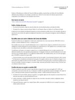
Introduce of the run LED
The run LED makes use of only a few components and circuit and needs a few signals of the
main board’s slot. The probability of the trouble with the run LED is very small. Even though you
plug the card in the bad slot, the card dose not indicate the error code, even to the extent that All
lights is off except that the run light can be quite possible to run normally. You can solve the
following problems by the result of “If the run LED had sparkled the main board had even run .”
1. The part of the codes of the card is bad;
2. The card is not compatible with the main board which you are using;
3. PCI slot or ISA slot is bad;
4. The card’s interface cannot match the slot well by the cause of the card ‘s plugging
incorrectly, the dirty of the interface, the rusty slot and so on.
5. The main board may stop running;
6. The main board is running with programs which is out of relation to the codes;
Distinguish true and false
The PI0050 is more compatible than the economical and really useful PI0049 with main board
of superior quality such as P
Ⅲ、
PIV and so on. So you can distinguish the PI0049 regarded as
PI0050 by their characteristics as follows, and also you can dial this number 086 139 2517 4332 or
write to me by E-mail: to the get lastest distinguishing messages.
●
There is “China Copyright 01224987.4”on the edge of PCB;
●
There is “China Copyright 513427”on PI0049
、
pi0050;
●
On the back of the card ,there is a telephone number of “086 139 2517 4332;
The characteristics of spurious cards that have been known:
●
”
中电电有电:
01223987.3”
●
”
电有技电:
01224988.3”
●
”
电利电:
02125087.5”(It is the patent of biology organic compound)
●
Be careful ! The spurious cards always are made of bad or unsuitable materials. It hasn’t been tested
by the professional equipment and has no simulation technique.
●
At the same time, there may be a few I0049 card regarded as the PI0050 card to sell.
TRUE
TRUE
FLAS
E
FLAS
E
Catalogue
⒈Synopsis……………………………………………………………………………………………
⒈Obligatory contents…………………………………………………………………………………
⒈Hexadecimal character table……………………………………………………………………….
4.Description of LED displays………………………………………………………………………
⒈Flow chart………………………………………………………………………………………….
⒈Error codes
table…………………………………………………………………………………….
⒈Description of beep code…………………………………………………………………………
(1) AMI BIOS beep codes (fatal error)……………………………………………………
(2) AMI BIOS beep codes (Non-fatal error)………………………………………………
(3) Award BIOS beep codes …………………………………………………………………
(4) Phoenix BIOS beep codes………………………………………………………………
(5) IBM BIOS beep codes……………………………………………………………………
⒈Corrective Action…………………………………………………………………………………
(1) If I forget the password, what can I do?………………………………………………….
①Omnipotent password……………………………………………………………………
a. AMI password…………………………………………………………………………
b. Award password…………………………………………………………………………
c. Other ways………………………………………………………………………………
②Discharge by software…………………………………………………………………….
③Discharge by
hardware……………………………………………………………………
④.Other way………………………………………………………………………………
(2) How to enter CMOS SETUP?……………………………………………………………
⒈Answers of frequently-asked questions…………………………………………………………….
⒈If the code is not included in the book, what can I do?……………………………… ……………
⒈SYNOPSIS
The card is named POST (Power On Self Test ) card too, it could display the error code by
the result of POST ,then you would soon determine cause of the error by error codes table.
Especially when the PC can’t boot operating system, or it is a black screen, or the card and
motherboard couldn’t issue an audible beep. It is a powerful diagnostic tool. Now just use it, you’ll
get twice the result with half the effort.
When the power is turned on, the BIOS first would have a strict test with system
circuit
、
memory
、
keyboard
、
video
、
hard disc
、
floppy drive and so on. It analyzes the system
configuration and initializes the basic I/O setup. At last when all is normal, it boots the operating
system .The obvious feature of testing crucial components is demarcate by curse’s appearing .At
first, the BIOS tests the crucial components .If the testing is abnormal, the computer stopped
compulsively; The curse cannot appear in the screen; There is no response to the screen. The BIOS
tests common components afterwards .If the testing is abnormal, the computer continues to run and
displays the information of error. When there is some trouble with the computer and the testing is
abnormal, especially the testing crucial component, no displaying in the screen, the black screen,
you can put the Post card in the expansive slot .You will know the cause of the trouble by the code
that the card indicates and the error codes table of this manual.
⒈OBLIGATORY CONTENTS
1.The error codes table is in the order of the codes’ value from small to big. The sequence in which
the code displays is decided by BIOS of the motherboard.
2. You must identify that the code that POST card displayed is "initiative code" or " Error code".
"initiative code" is meaningless.
①How do we distinguish "initiative code" or " Error code" of conventional two-bit-code
POST card?
When conventional two-bit-code POST card displayed a code. At first, we must see
whether there have been some other codes varying before the code is displayed. If there have
been some codes varying and it stops at a certain code in the end, the code is the" error code";
If the displayed code is first code and you cannot see any other code varying before it, the code
is the" initiative code". The "initiative code" is meaningless. But sometimes the speed of much
code varying is too fast so that by unaided eye we cannot make a judgement whether there
have been some other codes varying before it stops at the certain code that I can see in the end.
You need consider this code as the “Error code" here in this condition. If you have not solve
the trouble, this code must be the "initiative code".
As long as code "0000" or "FFFF" is displayed by four-bit-code POST card, the code "0000"
or "FFFF" is "initiative code". It is no need for you to make a judgment by unaided eye
whether there have been some other codes varying before it stops at the code "0000" or
"FFFF".
②Why is the "initiative code" meaningless?
The first code that is displayed when power is on is named "initiative code" by us,
because the debug card is also electronical device itself. When the power is on, the card will
display one two-bit code automatically. It is the initiative code. But the code is not the POST
code (referred to the "SYNOPSIS" in the chapter one of the manual) of the computer. So the
"initiative code" is meaningless.
3. The codes that haven’t been defined is not included in the table.
4. For the different BIOS (such as AMI
、
Award
、
Phoenix ), the code is meaning differently . So
you must make sure that which kind of BIOS you are testing by viewing the users’ guide
、
Seeing symbol on the BIOS IC of the motherboard or seeing the screen directly while the
computer booting
5. There is no more than some code displayed when you insert the card into the PCI slot on a few
brands of motherboards, but when you plug it into the ISA slot, all the code can be displayed.
At present, it has be discovered that all codes is displayed when you insert the card into the
PCI slot of several brands of computers which not all codes is displayed when you plug the
card in the ISA slot. So we suggest that you need plug the card from one slot to another slot
when consulting the code is unsuccessful. In addition, the different slot on the certain
motherboard in the different states. For example, all codes can be displayed from “00” to “FF”
when you plug the card in the PCI slot that is near the CPU on the motherboard DELL810 while
only a part of codes can be displayed from “00” to”38” when you plug the card in the other
PCI slot on the motherboard DELL810.
6. The time of PCI that the resetting signal needs is not always synchronized with the time of ISA
.So sometimes the code begin to be displayed when the card in the ISA, but the resetting light
of PCI has not been off while the card stops to display the original code.
7. As there are more and more different kinds and structures of the motherboard, and the codes of
BIOS POST is updated constantly, so the cause of trouble that error code indicates is just a
reference for you.
8.According to experience, the card of two-bit code is reliable if you plug it in the slot on the
motherboard below and including the P
Ⅱ
300. It will stop running or it dose not indicate the
error code or it indicates false error code. As until recently we haven’t received the bad reflect
about the four-bit code card of P0050. We suggest you buy and use the four-bit code card of
P0050.
⒈Hexadecimal character table
⒈Description of LED displays
LED Signal Type Description
RUN Bus pulse If the LED sparkles, the main board has been running. If
the man board hasn’t run, the LED is off.
CLK Bus clock As long as the main board is on power after you plug the
card in either PCI slot or ISA slot, the LED is on. or else
there is no bus clock signal.
BIOS Base input/output signals As long as the CPU is reading to BIOS when the board is
on powered, the LED sparkles.
IRDY Main equipments is ready The LED sparkles when there is a IRDY signal.
OSC Oscillation signal It is oscillation signal of ISA slot. The LED should be on,
As long as the Power is on after you plug the card in the
ISA slot on the main board. Or else the crystal oscillation
circuit is broken, and there is no OSC signal.
FRAME Frame periods It is cycle frame signal of PCI slot. The LED should be
on, As long as the Power is on after you plug the card in
the PCI slot on the main board. The LED sparkles when
the FRAME signal is coming. Or else there is no
FRAME signal. Lights all the time.
RST Resetting signal The LED ought to have been on for half second since you
press the power switch or the reset switch. If it is on all
the time, please check whether the resetting pin connects
to the accelerating switch or makes up a short circuit or
there is some trouble with the resetting circuit.
12V Power The LED should be on, As long as the Power is on after
you plug the card in the slot. Or else there is no voltage
of 12V or there is short circuit.
-12V Power The LED should be on, As long as the Power is on after
you plug the card in the slot. Or else there is no voltage
of-12V or there is short circuit.
5V Power The LED should be on, As long as the Power is on after
you plug the card in the slot. Or else there is no voltage
of 5V or there is short circuit.
-5V Power The LED should be on, As long as the Power is on after
you plug the card in the ISA slot. Or else there is no
voltage of-5V or there is short circuit. (There is own -5V
of ISA slot.)
3V3 Power There is the proper voltage of 3V3 of the PCI volt. The
LED should be on, As long as the Power is on after you
plug the card in the PCI slot, but sometimes the LED
may be off by the reason that there is no voltage of 3V3
of a few PCI slot or there is open circuit.
⒈Flow chart
Begin
Power off and remove all the cards that plug in expansion slot. Insert the card
into ISA or PCI slot. (Notice: When you plug it in the ISA slot the component
side should face to the power, if it plugged in the wrong direction, the card and
motherboard is not broken, but both the card and the main board stop running.
⒈Error code table
CODE Award AMI Phoenix4.0/Tandy3000
00 Copying code to
specific area is done.
Passing control to INT
19h boots loader next.
Power on; Judge If the all lights
run normally. (The BIOS light
may be on low power to sparkle
NO
According to the
“Description of LED
displaying ”, you can
find the cause of the
trouble and correct it
YES
Judge whether the error code that
means there is a trouble with the
main board is displayed
According to the error
code table, you can
find the cause of the
trouble and correct it
YES
NO
Power off, insert the display
card、I/O card、keyboard、hard
disk drive and expansion cards
Power on, Judge whether the error
code that means there is a trouble
with the main board is displayed
Power off, According to
the error code table, you
can find the cause of the
trouble and correct it
If the result of the test is correct even though it can’t boot
the operating system, there may be some trouble with the
software or disc drive, or disk controller, or DMA circuit.
NO
YES
End
Processor Test 1 verifies
Processor status (1FLAGS) .
Test the following processor
status flags: carry, zero, sign,
overflow.
The BIOS sets each flags and
verifies whether they are set.
After then It turns each flag
off and verifies whether it is
off.
02 Test All CPU Registers Except
SS, SP, and BP with Data FF
and 00
Verify Real Mode
03 Disable NMI, PIE, AIE, UEI,
SQWV.
The NMI is disabled.
Next, It checks a soft
reset or the power
condition
Disable Non maskable
Interrupt (NMI)
Disable video, parity checking,
DMA.
Reset math coprocessor.
Clear all page registers, CMOS
shutdown byte.
Initialize timer 0, 1, and2,
including set EISA timer to a
known state.
Initialize DMA controllers 0
and 1.
Initialize interrupt controllers 0
and 1.
Initialize EISA extended
registers.
04 RAM must be periodically
refreshed to keep the memory
from decaying. This refreshing
function is working properly.
Get CPU type
05 Keyboard Controller
Initialization
The BIOS stack has
been built. Next, it
disable cache memory.
DMA initialization is in
progress or fails
CODE Award AMI Phoenix4.0/Tandy3000
06 Reserved Uncompressing the
POST code next.
Initialize system
hardware
07 Verifies whether CMOS is
Working correctly, Detects
whether battery is bad
Initialize the CPU and
the CPU data area
subsequently.
Disable shadow and
execute code from the
ROM.
08 Early chip set initialization The CMOS checksum
is computed.
Initialize chipset with
initial POST values
Memory presence test
OEM chip set routines
Clear low 64K memory
Test first 64K memory
09 Initialize Cyrix CPU
Initialize Cache
0A Initialize first 120 interrupt
vectors with SPURIOUS-INT-
HDLR and initialize INT 00h-
1Fh according to INT-TBL.
The CMOS checksum
calculation is done.
Initialize the CMOS
status register for date
and time next.
Initialize CPU registers
0B Test CMOS RAM Checksum, if
it is bad, or INS Key is Pressed,
Load the default
The CMOS status
register is initialized.
Next, performing any
required initialization
before the keyboard
BAT command is
issued
Enable CPU cache
Detect Type of Keyboard
Controller.
Set NUM_LOCK Status
0D Detect CPU Clock;
Read CMOS location 14h to
find out type of video in use.
Detect and initialize video
adapter.
CODE Award AMI Phoenix4.0/Tandy3000
0E Test Video Memory and write
sign-on information to screen.
Setup shadow RAM? Enable
shadow according to setup.
Test DMA Cont. 0; BIOS
Checksum Test.
Detect and Initialize Keyboard.
10 Test DMA Controller 1 The keyboard
controller command
byte is written. Next,
issue the Pin 23 and 24
blocking and
unblocking command
Initialize Power
Management
11 Test DMA Page Registers Next, check if <End>
or <Ins> keys were
pressed during power
on. Initializing CMOS
RAM if the
Initialization CMOS
RAM in every boot
AMIBIOS POST
option was set in
AMIBCP or the <End>
key was pressed.
Load alternate registers
with initial POST values
12 Reserved Next, disabling DMA
controllers 1 and 2 and
interrupt controllers 1
and 2
Restore CPU control
word during warm boot
13 Reserved The video display has
been disabled. Port B
has been initialized.
Next, initialize the
chipset.
Initialize PCI Bus
primary devices
CODE Award AMI Phoenix4.0/Tandy3000
14 Test 8254 Timer 0 Counter 2 The 8254 timer test
will begin next.
Initialize keyboard
controller
15 Verify 8259 Channel 1
Interrupts by Turning Off and
On the Interrupt Lina
16 Verify 8259 Channel 2
Interrupts by Turning Off and
On the Interrupt Lina
BIOS ROM checksum
17 Turn Off Interrupts and verify
whether Non maskable
Interrupt Register is On
Initialize cache before
memory Auto size
18 Force an Interrupt and Verify
the Interrupt Occurring.
Initialize 8254 timer.
19 Test Stuck NMI Bits; Verify
whether NMI Can Be
Cleared
The 8254 timer test is
over. Starting. The
memory refresh test is
after that
1A Display CPU clock The memory
refreshing lina is
triggered. Check the
15 microsecond on/off
time next
Initialize 8237 DMA
controller
1B Reserved
1C Reserved Reset Programmable
Interrupt Controller
1D Reserved
1E Reserved
If EISA non-volatile memory
checksum is normal, execute
EISA initialization.
If not, execute ISA tests and
clear EISA mode flag.
Test EISA configuration
memory
Integrity (checksum &
communication interface).
20 Initialize Slot 0 (System Board) Test whether DRAM
refreshes.
21 Initialize Slot 1
22 Initialize Slot 2 Test 8742 Keyboard
Controller
CODE Award AMI Phoenix4.0/Tandy3000
23 Initialize Slot 3 Read the 8042 input
port and disable the
MEGAKEY Green PC
feature next. Make the
BIOS code segment
rewrite and perform
any necessary
configuration before
initializing the
interrupt vectors
24 Initialize Slot 4 The configuration is
required before
interrupt vector
initialization has
completed. Interrupt
vector initialization is
about to begin
Set ES segment register
to 4 GB
25 Initialize Slot 5 Interrupt vector
initialization is done.
Clearing the password
if the POST DIAG
switch is on.
26 1.test the exception situation of
protected mode. Please check
the memory of CPU and main
board.
2.no fatal trouble, VGA
displayed normally. If
nonfateful trouble occurred,
then display error message in
VGA, else Boot operating
system. Now code 26 is OK
code, and no any other codes
can be displayed.
1.Read
/write
、
input
、
output
port of 8042 keyboard,
readyfor resolve mode,
continue to get ready
for initialization of all
data,check the 8042
chips on main board.
2.refered to the left .
1.enable A20 address
line, check the A20 pins
of memory controlling
chips, and check circuit,
correlated to pins. In
memory slot, may be
A20 pin and memory
pins are not in contact, or
memory A20 pins bad.
2.refered to the left.
27 Initialize Slot 7 Any is initialized
before. Setting video
mode will be done
next
28 Initialize Slot 8 Initialization is done
before. Setting the
video mode
completes. Configure
the monochrome mode
and color mode
settings next
Auto size DRAM
29 Initialize Slot 9 Initialize POST Memory
Management
2A Initialize Slot 10 Initialize the different
bus system and static
output devices, if it is
present
Clear 512 KB base RAM
2B Initialize Slot 11 Passing control to the
video ROM to perform
any required
configuration before
the video ROM test.
2C Initialize Slot 12 All necessary
processing before
passing control to the
video ROM is done.
Look for the video
ROM next and pass
control to it.
RAM fails on address l
lina XXXX*
2D Initialize Slot 13 The video ROM has
returned control to
BIOS POST.
Performing any
required processing is
after the video ROM
had control.
2E Initialize Slot 14 Complete post-video
ROM test processing.
If the EGA/VGA
controller is not found,
perform the display
memory read/write test
next
RAM fails on data bits
XXXX* of low byte of
memory bus
2F Initialize Slot 15 The EGA/VGA
controller was not
found. The display
memory read/write test
is about to begin
Enable cache before
system BIOS shadow
30 Size of base Memory From
256K to 640K and Memory is
Extended Above 1MB.
The display memory
read/write test passed.
Look for retracing
checking next
31 Test Base Memory From 256K
to 640K and Memory Extended
Above 1MB
The display memory
read/write test or
retracing checking
failed. Perform the
alternate display
memory read/write test
next
32 If EISA Mode, Test EISA
Memory Found in Slots
Initialization
The alternate display
memory read/write test
passed. Look for
alternate display
retracing checking
next.
Test CPU bus-clock
frequency
33 Reserved Initialize Phoenix
Dispatch manager
34 Reserved Video display
checking is over. Set
the display mode next.
35 Reserved
36 Reserved Warm start and shut
down
37 Reserved The display mode is
set. Displaying the
information when it
boots next.
38 Reserved Initialize the bus input,
IPL and general
devices next, if present
Shadow system BIOS
ROM
39 Reserved Display bus
initialization error
messages.
3A Reserved The new cursor
position has been read
and saved. Display the
Hit <DEL> message
next
Auto size cache
3B Reserved The Hit <DEL>
message is displayed.
The protected mode
memory test is about
to start.
3C Setup Enabled Advanced configuration
of chipset registers
3D Detect if Mouse is Present,
Initialize Mouse, Install
Load alternate registers
with CMOS values
Interrupt Vectors
3E Initialize Cache Controller
3F Reserved
40 Display Virus Protest Disabled
or Enabled
Prepare the descriptor
tables next
41 Initialize Floppy Disk Drive
Controller and Any Drives
Initialize extended
memory for Rom Pilot
42 Initialize Hard Drive Controller
and Any Drives
The descriptor tables
are prepared. Enter
protected mode for the
memory test next
Initialize interrupt
vectors
43 Detect and Initialize Serial &
Parallel Ports and Game Port
Entered protected
mode. Enable
interrupts for
diagnostics mode next.
44 Reserved Interrupts is enabled if
the diagnostics switch
is on. Initialize data to
check memory
wrapping around at 0:0
next.
45 Detect and Initialize Math
Coprocessor
Data initialized. Check
for memory wrapping
around at 0:0 and find
the total system
memory size next
POST device
initialization
46 Reserved The memory wrapping
around test is done.
Memory size
calculation has been
done. Writing patterns
to test memory next
Check ROM copyright
notice
47 Reserved The memory pattern
has been written to
extended memory.
Write patterns to the
base 640 KB memory
next.
Initialize I20 support
48 Reserved Patterns write in base
memory. Determine
the amount of memory
below 1 MB next.
Check video
configuration against
CMOS
49 Reserved The amount of
memory below 1 MB
has been found and
verified. Determine the
amount of memory
above 1 MB memory
next.
Initialize PCI bus and
devices
4A
Reserved
Reserved
Initialize all video
adapters in system
4B Reserved The amount of
memory above 1 MB
has been found and
verified. Check for a
soft reset and clear the
memory below 1 MB
for the soft reset next.
If this is a power on
situation, go to
checkpoint 4Eh next.
Quiet Boot start
(optional)
4C Reserved The memory below 1
MB has been cleared
via a soft reset. Clear
the memory above 1
MB next.
Shadow video BIOS
ROM
4D Reserved The memory above 1
MB has been cleared
via a soft reset. Save
the memory size next.
Go to checkpoint 52h
next
4E Reboot if it is Manufacturing
Mode; If not, Display Messages
and Enter Setup
The memory test
started, but not as the
result of a soft reset.
Displaying the first 64
KB memory size next.
Display BIOS copyright
notice
4F Ask Password Security
(Optional)
The memory size
display has started.
The display is updated
during the memory
test. Perform the
sequential and random
memory test next
Initialize Multi Boot
50 Write All CMOS Values Back
to RAM and Clear
The memory below 1
MB has been tested
and initialized. Adjust
the displayed memory
size for relocation and
shadowing next.
Display CPU type and
speed
51 Enable Parity Checking. Enable
NMI, Enable Cache Before
Boot
The memory size
display was adjusted
for relocation and
shadowing. Testing the
memory above 1 MB
next.
Initialize EISA board
52 Initialize Option ROMs from
C8000h to EFFFFh or if
FSCAN Enabled to F7FFFh
The memory above 1
MB has been tested
and initialized. Saving
the memory size
information next.
Test keyboard
53 Initialize Time Value in 40h:
BIOS Area
The memory size
information and the
CPU registers are
saved. Enter real mode
next.
54 Shutdown was
successful. The CPU is
in real mode. Disable
the Gate A20 line,
parity, and the NMI
next
Set key click if enabled
55 Enable USB devices
57 The A20 address line,
parity, and the NMI are
disabled. Adjust the
memory size
depending on
relocation and
shadowing next.
58 The memory size was
adjusted for relocation
and shadowing. Clear
the Hit <DEL>
message next
Test for unexpected
interrupts
59 The Hit <DEL>
message is cleared.
The <WAIT >
message is displayed.
Start the DMA and
Initialize POST display
service
interrupt controller test
next.
5A Display prompt “Press
F2 to enter SETUP”.
5B Disable CPU cache
5C Test RAM between
512KB and 640 KB
60 Setup virus protection (boot
sector protection) functionality
according to setup setting.
The DMA page
register test passed.
Perform the DMA
Controller 1 base
register test next.
Test extended memory
61 Try to turn on level 2 cache (if
L2 cache has already turned on
in post 3D, this part will be
skipped)
Set the boot up speed according
to setup setting
Last chance for chipset is
initialized
Last chance for power
management is initialized(reen
BIOS only)
Show the system configuration
table
Setup NUM Lock Status
According to Setup values
Program the NUM lock, Set
matic rate & typematic speed
according to setup.
63 If there is any changes in the
hardware configuration. Update
the ESCD information (PnP
BIOS only)
Clear memory that have been
used
Boot system via INT 19h
64 Jump to UserPatch1
65 The DMA controller 2
base register test
passed. Programme
DMA controllers 1 and
2 next.
66 Complete
programming DMA
controllers 1 and 2.
Initialize the 8259
interrupt controller
next.
Configure advanced
cache registers
67 Complete 8259
interrupt controller
initialization.
Initialize Multi Processor
APIC
68 Enable external and CPU
caches
69 Set up System
Management Mode
(SMM) area
6A Display external L2
cache size
6B Load custom defaults
(optional)
6C Display shadow-area
message
6E Display possible high
address for UMB
recovery
6F
70 Display error message
71
72 Check for configuration
errors
76 Check for keyboard
errors
7C Set up hardware interrupt
vectors
7D Initialize Intelligent
System Monitoring
7E Initialize coprocessor if
present.
7F Enabling extended
NMI source is in
progress.
80 The keyboard test has
started. Clear the
output buffer and
check for stuck keys.
Issue the keyboard
reset command nex.t
Disable onboard Super
I/O ports and IRQs.
81 A keyboard reset error
or stuck key was
found. Issue the
keyboard controller
interface test command
next.
Late POST device
initialization.
82 The keyboard
controller interface test
completed. Write the
command byte and
initialize the circular
buffer next.
Detect and install
external RS232 ports
83 The command byte
was written and global
data initialization has
completed. Check for a
locked key nex.t
Configure non-MCD
IDE controllers
84 Locked key checking
is over. Check whether
a memory size
mismatch with CMOS
RAM data next.
Detect and install
external parallel ports
85 The memory size
check is done. Display
a soft error and check
for a password or by
passing WINBIOS is
Set up next.
Initialize PC-compatible
PnP ISA devices
86 The password was
checked. Perform any
required programming
before WINBIOS
Setup next.
Re-initialize onboard I/O
ports.
87 The programming
before WINBIOS
Setup has completed.
Uncompress the
WINBIOS Setup code
and execute the
AMIBIOS Setup or
WINBIOS Setup
utility next.
Configure Motherboard
Configurable Devices
(optional)
88 Returned from
WINBIOS Setup and
cleared the screen.
Perform any necessary
programming after
WINBIOS Setup next.
Initialize BIOS Data
Area
89 The programming after
WINBIOS Setup has
completed. Display the
power on screen
message next.
Enable Non-Maskable
Interrupts (NMIs)
8A Initialize Extended BIOS
Data Area
8B The first screen
message has been
displayed. The
<WAIT > message is
displayed. Perform the
PS/2 mouse check and
extended BIOS data
area allocation check
next.
Test and initialize PS/2
mouse
8C Programme the
WINBIOS Setup
options next.
Initialize floppy
controller
8D The WINBIOS Setup
options are
programmed. Reset the
hard disk controller
next.
8E The hard disk
controller has been
reset. Configure the
floppy drive controller
next.
8F Determine number of
ATA drives (optional)
90 Initialize hard-disk
controllers
91 The floppy drive
controller has been
configured. Configure
the hard disk drive
controller next.
Initialize local-bus hard-
disk controllers
92 Jump to UserPatch2
93 Build MPTABLE for
multi-processor boards
95 Initialize bus adaptor
ROMs from C8000h
through D8000h
Install CD ROM for boot
96 Initialize before
passing control to the
adaptor ROM at C800
Clear huge ES segment
register
97 Initialize before the
C800 adaptor ROM
gains control has
completed. The
adaptor ROM check is
next.
Fix up Multi Processor
table
98 The adaptor ROM had
control and has now
returned control to
BIOS POST. Perform
any required
processing after the
option ROM returned
control A
Search for option ROMs.
One long, two short
beeps on checksum fails.
99 Any initialization
required after the
option ROM test has
completed. Configure
the timer data area and
printer base address
next.
Check for SMART Drive
(optional)
9A Set the timer and
printer base addresses.
Set the RS-232 base
address next.
Shadow option ROMs
9B Returned after setting
the RS-232 base
address. Perform any
required initialization
before the Coprocessor
test next.
9C Required initialization
before the Coprocessor
test is over. Initialize
the Coprocessor next
Set up Power
Management
9D Coprocessor
initialized. Perform
any required
initialization after the
Coprocessor test next.
Initialize security engine
(optional)
9E Initialization after the
Coprocessor test is
complete. Check the
extended keyboard,
keyboard ID, and Num
Lock key next. Issuing
the keyboard ID
command next
Enable hardware
interrupts
9F Determine number of
ATA and SCSI drives
A0 Set time of day
A1 Check key lock
A2 Display any soft error
next
A3 The soft error display
has completed. Set the
keyboard typematic
rate next.
A4 The keyboard
typematic rate is set.
Programme the
memory wait states
next
Initialize typematic rate
A5 Memory wait state
programming is over.
Clear the screen.
Enable parity and the
NMI next
A7 NMI and parity is
enabled. Perform any
initialization required
before passing control
to the adaptor ROM at
E000 next.
A8 Initialization before
passing control to the
adaptor ROM at
E000hm is completed.
Pass control to the
adaptor ROM at
Erase F2 prompt