Basic Geotechnical Earthquake Phần 7 docx
Bạn đang xem bản rút gọn của tài liệu. Xem và tải ngay bản đầy đủ của tài liệu tại đây (258.12 KB, 16 trang )
86 Basic Geotechnical Earthquake Engineering
middle one-third of footing. q′= 89.988 kN/m
2
from Eq. (7.9). q
ult
in Eq. (7.11) is
determined using Eq. (7.6) which makes use of Fig. 7.1. Hence q
ult
= 330 kN/m
2
.
Consequently, Factor of safety = FS = 3.667.
(b) For 2 m wide square spread footing, Q = P = 600 kN, e = M/Q = 150/600
= 0.25 m. For middle one-third of footing, e can not exceed 0.33 m, and therefore
e is within middle one-third of footing. Q = 600/2 = 300 kN/m for use in Eq. (7.9).
q′ = 262.5 kN/m
2
from Eq. (7.9) for 2m wide square spread footing. Furthermore,
T = 1.8 + 1.2 – 0.5 = 2.5m. c
2
= 0 and c
1
= 60 kN/m
2
. T/B = 2.5/2 = 1.25m
and c
2
/c
1
= 0. Using these and from Fig. 7.1, N
c
= 3.2. Hence q
ult
= 249.6 kN/
m
2
from Eq. (7.7) with B = L = 2 m. Consequently, Factor of safety = FS = 0.95.
Home Work Problems
1. Solve Example 7.1 assuming that both the existing 1.2 m thick and additional 1.8m thick
unliquefiable soil layer is cohesionless with effective friction angle equal to 31°. Coefficient of
earth pressure at rest is equal to 0.5. Total unit weight of soil above water table is 18.3 kN/m
3
and buoyant unit weight of soil below water table is 9.7 kN/m
3
. Water table is at a depth of
1.2m below existing ground surface. (Ans. (a) FS = 0.8 (b) FS = 0.32)
2. Perform total stress analysis using Terzaghi equations for general and local shear failure to
find out factor of safety for 2 m wide square spread footing. Use data from Example 7.1.
(Ans. FS = 1.664)
3. Use data from Example 7.1. Assume that apart from vertical loads, the strip and the spread
footing is subjected to earthquake induced moment equal to 5 kN.m/m and 150 kN.m which
act in single (B) direction. Determine factor of safety using Eq. (7.12) (Ans. (a) FS = 4.58
(b) FS = 1.176.
4. A site consists of a sand deposit with a fluctuating groundwater table. The expected depth
of footing will be 0.5 to 1 m. Assume that groundwater table can rise to a level close to
footing base. Buoyant unit weight of sand is 9.65 kN/m
3
, effective friction angle for sand =
32° and pore water pressure ratio = 0.2. Using factor of safety of 5, determine allowable
bearing capacity for:
(a) 1.5m wide strip footing.
(b) 2.5m wide square spread footing.
(Ans. (a) 24.318 kPa (b) 32.424 kPa))
5. What are the guidelines to calculate undrained shear strength in the bearing capacity analysis
for cohesive soil weakened by earthquake?
EARTHQUAKE RESISTANT DESIGN
OF DEEP FOUNDATION
8
CHAPTER
87
8.1 INTRODUCTION
Deep foundations are used when the upper soil stratum is too soft, weak or compressible
to support the static and earthquake induced foundation loads. Deep foundations are also
used when there is possibility of undermining of the foundation, either in static or earthquake
induced foundation loading condition. One example is bridge pier which is often founded on
deep foundation to prevent a loss of support due to flood conditions which could cause river
bottom scour. Furthermore, in the case of excessive settlement, there is bearing capacity
failure due to liquefaction of underlying soil deposit as well as ground surface damage during
earthquake. To prevent consequent structural damage, deep foundations are used.
The most common types of deep foundations are piles and piers supporting individual
footing or mat foundations. Piles are relatively long, slender, columnlike members. They
are often made up of steel, concrete or wood. Either they are driven in or cast in place in
predrilled holes. There are different types of piles. Batter piles are driven at an angle
inclined to vertical. This provides high resistance to lateral loads. If the soil liquefies during
earthquake, lateral resistance of batter pile may be significantly reduced. End-bearing pile
is another type of pile. For end-bearing piles, the support capacity of pile is derived principally
from the resistance of foundation material on which pile tip rests. End-bearing piles are
used when a soft layer is underlain by dense or hard stratum. If upper soft layer liquefies
during earthquake, the pile will be subjected to down drag forces. Consequently, pile must
be designed to resist these soil-induced forces. In friction piles, support capacity of pile is
derived principally from the resistance of soil friction and/or adhesion mobilized along side
of pile. They are used in soft clays where the end bearing resistance is small due to
punching shear at pile tip. If the soil is subjected to liquefaction during earthquake, both
the frictional resistance and lateral resistance of pile may be lost during earthquake. Combined
end bearing and friction piles are another type of piles. These piles derive its support
88 Basic Geotechnical Earthquake Engineering
capacity from combined end bearing resistance developed at pile tip and friction and/or
adhesion resistance on pile perimeter.
Pier is defined as a deep foundation system. It is similar to cast in place pile. Pier
consists of a column like reinforced concrete member. Piers have often large enough diameter
to enable down hole inspection. They are also referred to as drilled shafts, bored piles or
drilled caissons.
There are some more techniques available for forming deep foundation elements resistant
to earthquake. Mixed in place soil cement or soil lime piles are called mixed in place piles.
Vibroflotation is another method used to make a cylindrical, vertical hole. This hole is filled
with compacted open graded gravel or crushed rock. These stone columns also have the
additional capacity of reducing the potential for soil liquefaction. This is achieved by allowing
earthquake induced pore water pressures to dissipate rapidly. The pore water flows into the
highly permeable open-graded gravel or crushed rock. They are also called vibroflotation-
replacement stone columns. Grouted stone columns are also used. In grouted stone columns,
voids are filled up with bentonite-cement or water-sand-bentonite cement mixtures. Concrete
vibroflotation column is also used as deep foundation element. In concrete vibroflotation
columns, concrete is used instead of gravel to fill the hole. All these special types of pile
foundations are used as earthquake resistant piles.
8.2 DESIGN CRITERIA
Different items are used in designing and construction of piles which can resist earthquake
induced loads. They are given in subsections below.
8.2.1 Engineering Analysis
Based on the results of engineering analysis, it has been suggested that deep foundation
should be designed and constructed such that it penetrates all the soil layers that are expected
to liquefy during earthquake. In these cases, deep foundations derive support from unliquefiable
soil located below potentially troublesome soil strata which is prone to liquefaction. Possibility
of down drag forces as well as loss of lateral resistance due to soil liquefaction should be
incorporated in the analysis. If a liquefiable soil layer is located below bottom of deep
foundation, then punching shear analysis should be used because there is possibility of deep
foundation’s punching into underlying soil strata. This analysis has already been explained in
the context of shallow foundations. For end-bearing piles, load applied to pile cap can be
assumed to be transferred to pile tip. Based on shear strength of unliquefiable soil below
bottom of piles as well as vertical distance from pile tip to liquefiable soil layer, factor of
safety can be calculated using Equations (7.1) and (7.2). B and L represents width and length
respectively of pile group.
8.2.2 Field Load Tests
Prior to foundation construction, a pile or pier should be load tested in field. Testing
is necessary to determine its carrying capacity. There are uncertainities involved in engineering
analysis of pile design. Consequently, pile load tests are recommended. Pile load test result
Earthquake Resistant Design of Deep Foundation 89
in more economical foundation than those based solely on engineering analysis. These tests
are useful to evaluate dynamic loading conditions as well. The test method is used to provide
data on strain of pile under impact load. Force, acceleration, velocity and displacement of a
pile under impact load is also obtained from these tests. These data are used to estimate
bearing capacity and integrity of pile. Hammer performance, pile stresses and soil dynamic
characteristics are also obtained from these data. However, field load tests can’t simulate
response of pile for situations where soil is expected to liquefy during design earthquake.
Consequently, results of pile load tests would have to be modified for the expected liquefaction
conditions.
8.2.3 Application of Pile Driving Resistance
Initially the pile capacity was estimated based on driving resistance. Driving resistance
was obtained during installation of pile. Pile driving equations were developed. They are
called Engineering News Formula. These equations relate the pile capacity to the energy of
pile driving hammer as well as the average net penetration of pile per blow of the pile
hammer (White, 1964). However, no satisfactory relationship between pile capacity from pile
driving equations and pile capacity measured from load tests have been observed. It has been
concluded that pile driving equations are no longer justified (Terzaghi and Peck, 1967).
Furthermore, for high displacement piles that are closely spaced, the vibration and soil displacement
associated with pile driving densifies granular soil around the pile. Consequently, the liquefaction
resistance of soil is increased due to pile driving.
8.2.4 Specifications and Experience
Other factors included in earthquake resistant deep foundation design include governing
building code, agency requirement and local experience. Local experience, such as deep
foundation performance during prior earthquakes, can be a important factor in the design
and construction of pile foundations.
Home Work Problems
1. What are the design criteria for earthquake resistant design of deep foundations?
90 Basic Geotechnical Earthquake Engineering
SLOPE STABILITY ANALYSES
FOR EARTHQUAKES
9
CHAPTER
90
9.1 INTRODUCTION
Slope movement is secondary effect of earthquake. There can be many types of earthquake
induced slope movement. For rock slopes, earthquake induced slope movement is divided
into falls and slides. Falls have relatively free falling nature of rock or rocks due to earthquake.
In slides, there is shear displacement along a distinct failure surface due to earthquake. Falls
and slides occur in soil slopes also. In addition, slope can be subjected to flow slide or lateral
spreading also during earthquake. For a specific type of earthquake induced slope movement
to occur, minimum slope inclination is required which ranges from 40° in earthquake induced
rock fall to 0.3° in liquefaction induced lateral spreading.
For seismic evaluation of slope stability, analysis can be grouped in two general
categories:
1. Inertia slope stability analysis
2. Weakening slope stability analysis
Inertia slope stability analysis is preferred if material retains its shear strength during
earthquake. Pseudostatic and Newmark are two common methods in this analysis. Weakening
slope stability analysis is preferred if material experiences significant shear strength reduction
during earthquake. During liquefaction, there are two cases of weakening slope stability
analyses. Flow slide develops when the static driving forces exceed shear strength of soil
along failure surface. In lateral spreading static driving forces do not exceed shear strength
of soil along slip surface. Instead, driving forces only exceed resisting forces during those
portions of earthquake that impart net inertial forces in the downward direction. This results
in progressive and incremental lateral movement.
Massive crystalline bedrock and sedimentary rock (retaining intact during earthquake),
soils which dilate during seismic shaking, soils not exhibiting reduction in shear strength with
Slope Stability Analyses for Earthquakes 91
strain, clay with low sensitivity, soils located above water table and landslides having distinct
rupture surface are examples where material retain shear strength during earthquake. Inertia
slope analyses is preferred for them.
Foliated or friable rock which fractures during earthquake, sensitive clays, overloaded
soft and organic soils as well as loose soils located below water table and under liquefaction
induced excess pore water pressure are examples where material experience sufficient shear
strength reduction during earthquake. Weakening slope stability analyses is preferred for
them.
9.2 INERTIA SLOPE STABILITY-PSEUDOSTATIC METHOD
This method is easy to understand and is applicable for both total and effective stress
slope stability analyses. The method ignores cyclic nature of earthquake. It assumes that
additional static force is applied on the slope due to earthquake. In actual analysis, a lateral
force acting through centroid of sliding mass is applied which acts in out of slope direction.
This pseudostatic lateral force F
h
is calculated as follows:
F
h
= ma =
Wa
g
Wa
g
kW
max
h
==
(9.1)
where, F
h
= horizontal pseudostatic force acting through centroid of sliding mass in
out of slope direction. For two dimensional analysis, slope is usually
assumed to have unit length.
m = total mass of slide material.
W = total weight of slide mass.
a = acceleration, maximum horizontal acceleration at ground surface due to
earthquake. ( = a
max
)
a
max
= peak ground acceleration.
a
max
/g = seismic coefficient.
Earthquake subjects sliding mass in general to vertical as well as horizontal pseudostatic
forces. Since vertical pseudostatic force on sliding mass has very little effect on its stability,
it is ignored.
Based on the results of field exploration and laboratory testing, unit weight of soil or
rock can be determined. Consequently, weight of sliding mass, W can be readily calculated.
On the other hand, selection of seismic coefficient takes considerable experience and judgement.
Certain guidelines regarding selection of seismic coefficient is as follows:
1. Higher the value of peak ground acceleration, higher the value of k
h
.
2. k
h
is also determined as function of earthquake magnitude.
3. When items 1 and 2 are considered, k
h
should never be greater than a
max
/g.
4. Sometimes local agencies suggest minimum value of seismic coefficient.
5. For small slide mass, k
h
= a
max
/g
92 Basic Geotechnical Earthquake Engineering
6. For intermediate slide mass, k
h
= 0.65a
max
/g
7. For large slide mass, k
h
= 0.1 for sites near faults generating 6.5 magnitude earthquake
and , k
h
= 0.15 for sites near faults generating 8.5 magnitude earthquake.
8. k
h
= 0.1 for severe earthquake, = 0.2 for violent and destructive earthquake and
= 0.5 for catastrophic earthquake.
9.2.1 Wedge Method
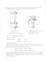
This is simplest type of slope stability analysis (refer Fig. 9.1). Failure wedge has planar
slip surface, inclined at an angle α to horizontal. Analysis could be performed for the case
of planar slip surface intersecting the face of slope or passing through toe of slope.
Fig. 9.1 Wedge method (Courtesy: Day, 2002)
As per pseudostatic wedge analysis of Fig. 9.1, four forces are acting:
W = weight of failure wedge = total unit weight γ
t
times cross-sectional area of failure wedge for
assumed unit length of slope.
F
h
=k
h
W = horizontal pseudostatic force acting through
centroid of sliding mass in out of slope direction.
N = normal force acting on slip surface.
T = shear force acting along slip surface.
For total stress analysis:
T = cL + Ntanφ = s
u
L
Slope Stability Analyses for Earthquakes 93
For effective stress analysis:
T= c′L + N′tanφ′
where,
L = length of planar slip surface
c, φ = shear strength parameters for total stress analysis
s
u
= undrained shear strength of soil for total stress analysis
N = total normal force acting on slip surface
c′φ′ = shear strength parameters for effective stress analysis
N′ = effective normal force acting on slip surface
Factor of safety for pseudostatic analysis is obtained as follows:
For total stress analysis:
FS =
α− α φ
+φ
==
α+ α α+ α
h
hh
cL+(W cos F sin ) tan
resisting force cL N tan
driving forces Wsin F cos W sin F cos
(9.2a)
For effective stress analysis:
FS =
′+ α− α− φ′
′+ ′ φ′
=
α+ α α+ α
h
hh
cL (Wcos F sin uL)tan
cL Ntan
Wsin F cos Wsin F cos
(9.2b)
where, FS = factor of safety for pseudostatic analysis
u = average pore water pressure along slip surface
For total stress analysis, total stress parameters of soil should be known and is often
performed for cohesive soils. For effective stress analysis, effective stress parameters of soil
should be known and is often performed for cohesionless soils. For effective stress analysis,
pore water pressure along slip surface should also be known. For soil layers above water table,
pore water pressure is assumed zero. If the soil is below water table and water table is
horizontal, pore water pressure below water table is hydrostatic. In the case of sloping water
table flow net can be used to estimate pore water pressure below water table.
9.2.2 Method of Slices
In this method, failure mass is subdivided into vertical slices and factor of safety is
determined based on force equilibrium equations. A circular arc slip surface and rotational
type of failure mode is often used in this method.
The resisting and the driving forces are calculated for each slice and then summed to
obtain factor of safety of the slope. The equation to calculate factor of safety is identical to
Eq. (9.2), with driving and resisting forces calculated for each slice and then summed to
obtain factor of safety. However, there are more unknowns than equilibrium equations in the
method of slices. Consequently, an assumption is to be made concerning interslice forces. In
ordinary method of slices, resultant of interslice forces is parallel to average inclination of
slice, α. Bishop simplified, Janbu simplified, Janbu generalized, Spencer method and Morgenstern-
94 Basic Geotechnical Earthquake Engineering
Price method are other methods of slices. Because of the tedious nature of calculations,
computer programs are routinely used to perform the pseudostatic slope stability analysis
using the method of slices. It has not been discussed in detail in this book.
9.2.3 Other Slope Stability Considerations
Important factors which are needed in the cross section to be used for pseudostatic
slope stability analysis is as follows:
Different soil layers: If the slope contains different soil or rock type, with different
engineering properties, it must be incorporated in the analysis. For all soil layers, either
effective shear strength or shear strength in terms of total stress parameters must be known.
Horizontal pseudostatic force is specified for every layer.
Slip surfaces: Either planar or composite type slip surface may be needed for analysis.
Tension cracks: Tension cracks at the top of slope can reduce factor of safety of a
slope by as much as 20 percent. This should be included in the analysis. Destabilizing effects
of water in tension cracks should also be included in the analysis.
Surcharge loads: Surcharge loads (at top or even on slope face) as well as tie-back
anchors should be included in the analysis.
Nonlinear shear strength envelope: If shear strength envelope of soil is non linear,
it should be included in the analysis.
Plane strain condition: Long uniform slopes are plane strain condition. Friction angle
in this case is about 10% higher than the friction angle obtained in triaxial experiment. This
should be included in the analysis.
These considerations are incorporated in Eq. (9.2) to complete the analysis as per
actual conditions.
9.3 INERTIA SLOPE STABILITY – NEWMARK METHOD
Purpose of this method is to estimate the slope deformation for those cases where the
pseudostatic factor of safety is less than 1.0, which corresponds to failure condition. It is
assumed that slope will deform during those portions of earthquake when out of slope
earthquake forces make pseudostatic factor of safety below 1.0 and the slope accelerates
downwards. Longer the duration for which pseudostatic factor of safety is zero, greater the
slope deformation.
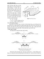
Fig. 9.2(a) shows horizontal acceleration of slope during earthquake. Accelerations
plotting above zero line are out of slope and accelerations plotting below zero line are into
slope accelerations. Only out of slope accelerations cause downslope movement and are used
in the analysis. a
y
in Fig. 9.2(a), is horizontal yield acceleration and corresponds to pseudostatic
factor of safety exactly equal to 1. Portion of acceleration pulses above a
y
(darkened portion
in Fig. 9.2(a)), causes lateral movement of slope. Fig. 9.2(b) and (c) represent horizontal
velocity and slope displacement due to darkened portion of acceleration pulse. Slope displacement
is incremental and occurs only when horizontal acceleration due to earthquake exceeds a
y
.
Slope Stability Analyses for Earthquakes 95
Fig. 9.2 Diagram illustrating Newmark method (a) acceleration versus time (b) velocity versus time for
darkened portion of acceleration pulse (c) corresponding downslope displacement versus time in
response to velocity pulses (Courtesy: Day, 2002)
Magnitude of slope displacement depends on variety of factors. Higher the a
y
value,
more stable the slope is for a given earthquake. Greater the difference between peak ground
acceleration a
max
due to earthquake and a
y
, larger the downslope movement. Longer the
earthquake acceleration exceeds a
y
, larger the downslope deformation. Larger the number of
acceleration pulses exceeding a
y
, greater the cumulative downslope movement during earthquake.
Most common method used in Newmark method is as follows:
log d = 0.90 + log
−
−
2.53 1.09
yy
max max
aa
1
aa
(9.3)
where, d = estimated downslope movement due to earthquake in cm.
a
y
= yield acceleration.
a
max
= peak ground acceleration of design earthquake.
Essentially a
max
must be greater than a
y
. While using Eq. (9.3), pseudostatic factor of
safety is determined first using the technique described in Fig. 9.2. If it is less than 1, k
h
is
reduced till pseudostatic factor becomes equal to 1. This value of k
h
is used to determine a
y
using Eq. (9.1). This a
y
and a
max
is used to determine slope deformation. Analysis is more
accurate for small and medium size failure masses.
9.3.1 Limitations of Newmark Method
Major assumption of Newmark method is that the slope will deform only when peak
ground acceleration exceeds yield acceleration. Analysis is most appropriate for wedge type failure.
96 Basic Geotechnical Earthquake Engineering
One limitation of Newmark method is that it is unreliable for slopes not deforming
as single massive block. Slope composed of dry and loose granular soil is such slope.
Earthquake induced settlement of dry and loose granular soils depend on relative density,
maximum shear strain induced by earthquake and number of shear strain cycles. It is
anticipated that the lateral movement of slope is the same order of magnitude as the
calculated settlement.
9.4 WEAKENING SLOPE STABILITY-FLOW SLIDES
Weakening slope stability is preferred for materials which experience significant reduction
in shear strength during earthquake. Analysis is done for flow slides in this section. Flow
slides develop when static driving forces exceed weakened shear strength of soil along slip
surface. Consequently, factor of safety is less than 1. There are three types of flow slides.
Mass liquefaction occurs when nearly the entire sloping mass is susceptible to liquefaction.
They occur to partially or fully submerged slopes. First step of analysis is to determine factor
of safety against liquefaction. If the entire sloping mass or a significant part of it is subjected
to liquefaction during earthquake, slope will be susceptible to flow slide.
Zonal liquefaction occurs when there is specific zone of liquefaction within the slope.
First step is to determine the location of zone of soil expected to liquefy during design
earthquake. Slope stability analysis is performed using circular arc slip surfaces passing through
zone of expected liquefaction. If factor of safety of slope is less than 1, flow slide is likely
to occur during earthquake.
Landslide movement due to soil liquefaction occurs due to liquefaction of horizontal
soil layers. There could be liquefaction of layers of saturated soil within the slope. This can
cause entire slope to move laterally along liquefied layer at base. Potential liquefiable soil
layer may be thin, hard to discover during subsurface exploration and hence it is difficult to
evaluate landslide movement possibility due to earthquake. Since slip surface must pass through
these horizontal layers, slope stability analysis is often performed using block type failure mode.
9.4.1 Factor of Safety Against Liquefaction for Slopes
First step is to determine zones likely to liquefy due to earthquake and to determine
factor of safety against liquefaction. For level ground it can be determined using analysis
presented in Chapter 6. This factor of safety thus obtained should be adjusted for sloping
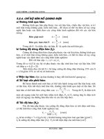
ground conditions. This is done using chart of Fig. 9.3.
In Fig. 9.3, horizontal axis is α, defined as:
α =
′
τ
σ
h static
vo
(9.4)
where, τ
h static
= static shear force acting on horizontal plane.
′
σ
vo
= vertical effective stress.
Slope Stability Analyses for Earthquakes 97
Fig. 9.3 Chart for use to adjust factor of safety against liquefaction for
sloping ground (Courtesy: Day, 2002)
For infinite slopes, α is approximately equal to slope ratio ( = vertical distance/horizontal
distance). Vertical axis of Fig. 9.3 is K
α
. To determine factor of safety against liquefaction for
sloping ground, factor of safety against liquefaction obtained from Chapter 6 is multiplied
with K
α
of Fig. 9.3. D
r
in Fig. 9.3 represents relative density of soil.
There are some approximate suggested guidelines. For α
< 0.10, use K
α
= 1.0. For D
r
> 45%, use K
α
= 1.0. For α > 0.10 and D
r
< 45%, K
α
is determined from Fig. 9.3 which
requires considerable experience and judgement.
9.4.2 Stability Analysis for Liquefied Soil
Factor of safety against liquefaction based on level ground surface is determined first
at various soil depths. Then this factor of safety is adjusted for sloping ground conditions
using Fig. 9.3. If the entire soil depth, or significant portion of it will be subjected to
liquefaction, then the slope will be susceptible to flow slides.
For the case of zonal liquefaction, slope stability analysis is required for soil that is
likely to liquefy during earthquake. There are two different approaches. In the first approach,
pore water pressure ratio ( = u/(γ
t
h) ) of liquified soil is taken as 1. u is pore water pressure,
γ
t
= total unit weight of soil, and h = depth below ground surface. Pore water pressure ratio
1 means pore water pressure is equal to total stress and hence effective stress is zero. This
approach is used with effective stress analysis and when effective cohesion of soil is zero. If
soil doesn’t liquefy during earthquake, effective shear strength parameters and estimated
pore water pressures are used in slope stability analysis. Second approach assumes liquefied
soil to have zero shear strength. For total stress analysis, undrained shear strength (s
u
) is zero
and for effective stress analysis effective stress parameters are zero. However, shear strength
of liquefied soil may not necessarily be equal to zero. This undrained liquefied shear strength
2.0
1.5
1.0
0.5
0
D
r
= 55 – 70%
D
r
= 45 – 50%
D
r
= 35%
σ′
v0
≥ 3 tons/ft
2
0 0.1 0.2 0.3 0.4
α
K
α
98 Basic Geotechnical Earthquake Engineering
is termed as liquefied shear strength. It has been found to be correlated with (N
1
)
60
value.
But, since undrained liquefied shear strength is very small, most conservative slope stability
analysis is performed for flow slides using effective stress analysis assuming liquefied shear
strength equal to zero. Further details are beyond the scope of this book.
9.5 WEAKENING SLOPE STABILITY-LIQUEFACTION INDUCED LATERAL SPREADING
If the liquefaction induced lateral spreading is restricted to localized ground surface,
it is called localized lateral spreading. If it causes lateral movement over an extensive distance,
it is called large scale lateral spreading. Large scale lateral spreading has been discussed in
detail. Concept of cyclic mobility is used to describe large scale lateral spreading. The driving
forces only exceed resisting forces during those portions of earthquake that impart net inertial
force in downward direction. Each cycle of net inertial force causes driving forces to exceed
resisting forces resulting in progressive and incremental lateral movement. Usually the ground
surface first cracks at unconfined toe and then ground cracks progressively move upslope.
Amount of horizontal ground displacement resulting from liquefaction induced lateral
spreading is determined using empirical methods. They have been developed based on regression
analysis. These equations are as follows:
For lateral spreading towards free face (river bank for example):
log D
H
= –16.366 + 1.178M – 0.927logR – 0.013R + 0.657logW + 0.348logT
+ 4.527log(100-F) – 0.922D
50
(9.5)
For lateral spreading of gently sloping ground:
log D
H
= –15.787 + 1.178M – 0.927logR - 0.013R + 0.429logS + 0.348logT
+ 4.527log(100-F) – 0.922D
50
(9.6)
where, D
H
= horizontal ground displacement due to lateral spreading, meters.
M = earthquake magnitude of design earthquake.
R = distance to expected epicenter or nearest fault rupture of design earthquake
in km.
W = free face ratio, expressed as percentage, = 100H/L. H is height of
free face and L is horizontal distance from base of free face to site
location.
T = cumulative thickness (meters) of submerged sand layers having (N
1
)
60
< 15.
F = fines content of soil comprising layer T, expressed as percentage. It
is percent of soil particles based on dry weight that pass No. 200
sieve.
D
50
= grain size corresponding to 50 percent fines of soil comprising layer
T, mm.
S = slope gradient (vertical/horizontal), expressed as percentage.
Slope Stability Analyses for Earthquakes 99
Furthermore, it has been reported that sites subjected to M ≤ 8 earthquake and have
soils with (N
1
)
60
values > 15 are resistant to lateral spreading. Equations 9.5 and 9.6 need
not be applied. Equations 9.5 and 9.6 are accurate within a factor of ± 2 and D
H
from these
equations should be multiplied by 2 for conservative design estimate of lateral spreading.
To obtain reliable deformations, terms in Equations (9.5) and (9.6) must be within
following ranges:
6
< M < 8
1% < W < 20%
0.1% < S < 6%
1m
< T < 15m
F
< 50%
D50
< 1mm
Other limitations of Equations (9.5) and (9.6) are:
(i) Liquefied soil layer must be within 10m of ground surface.
(ii) Equations (9.5) and (9.6) overestimate displacement due to lateral spreading of
liquefied gravels.
(iii) Equation (9.5) should be applied with caution at sites very close to free face.
(iv) For free face, both Equations (9.5) and (9.6) should be used. Higher value should
be used in actual design.
9.5.1 Summary
The liquefaction of soil can cause flow failure or lateral spreading. Even with factor of
safety against liquefaction greater than 1, there could still be significant weakening of soil and
deformation of slope. To summerize:
1. For factor of safety against liquefaction
< 1, soil is expected to liquefy due to
earthquake. Flow slide analysis (sec. 9.4) and/or lateral spreading analysis (sec. 9.5)
will be performed.
2. For factor of safety against liquefaction > 2, the pore water pressure due to earthquake
is usually small. It can be neglected. Soil is not weakened by earthquake and inertia
slope stability analysis (sec. 9.2 and sec. 9.3) will be performed.
3. For factor of safety against liquefaction greater than 1 and less than or equal to 2,
soil is not expected to liquefy due to earthquake. However, there could be substantial
pore water pressure increase. Pore water pressure ratio can be estimated as a function
of factor of safety against liquefaction. Using this pore water pressure ratio, effective
stress slope stability analysis could be performed. If analysis shows factor of safety
less than 1, failure of slope during earthquake is expected.
Example 9.1:
A slope has a height of 9.1 m and the slope face is inclined at 2:1 (horizontal:vertical).
Assume wedge type analysis, where slip surface is planer through toe of slope and is inclined
100 Basic Geotechnical Earthquake Engineering
at 3:1 (horizontal:vertical). Total unit weight of slope material = 18.1 kN/m
3
. Using undrained
shear strength parameters of c = 14.5 kPa and φ = 0, calculate factor of safety for static case
and for earthquake condition of k
h
= 0.3. Assume that it is not a weakening type soil.
Solution:
Refer Fig. 9.1, for the information given in the problem, area of the wedge = 0.5(9.1)(27.3
– 18.2) = 41.4m
2
. For unit length of slope, total weight of wedge, W = (41.4)(18.1) = 750
kN/m.
Static case:
F
h
=0
Using Eq. (9.2(a)) and the information given in the problem:
c = 14.5 kN/m
2
, φ = 0, α = tan
–1
1/3 = 18° and L = 9.1/sin α = 9.1/sin 18 = 29 m.
Substituting the values in Eq. (9.2(a)):
FS =
=
(14.5)(29)
1.8
(750)(sin 18)
Earthquake case:
F
h
= 0.3 W.
Other values are same as static case. Substituting the values in Eq. (9.2(a)):
FS =
=
+
(14.5)(29)
0.94
(750)(sin 18) (0.3)(750)(cos 18)
Example 9.2:
Use data from Example 9.1. Calculate slope deformation based on Newmark method.
Peak ground acceleration a
max
= 0.3 g.
Solution:
Since pseudostatic factor of safety is less than 1, slope deformation based on Newmark
method can be estimated. From Eq. 9.2(a), for FS =1, k
h
comes out to be 0.26. Hence a
y
= 0.26 g. a
max
= 0.3 g, given. Substituting in Eq. (9.3),
log d = –1.25. So d = 0.06cm
Example 9.3
:
A slope is inclined at an angle of 14°. Relative density of soil comprising slope is 35%.
Factor of safety against liquefaction for level ground is 1.25. Find out factor of safety against
liquefaction for sloping ground. Assume slope to be infinite.
Solution:
For infinite slope, α = tan 14 = 0.25. Also, relative density of soil = 35%. From Fig.
9.3, K
α
= 0.5. Hence, factor of safety for sloping ground condition = (1.25)(0.5) = 0.625.
Slope Stability Analyses for Earthquakes 101
Home Work Problems
1. Use data from Example 9.1, except assume that slip surface has effective shear strength of
c′ = 4 kPa and φ′ = 29°. Average measured steady state pore water pressure u = 2.4kPa.
Determine factor of safety of failure wedge based on effective stress analysis for static condition
and earthquake condition of k
h
= 0.2. It is not weakening type soil and pore pressure will
not increase due to earthquake. (Ans. static FS = 2.04, earthquake FS = 1.194)
2. Use data from problem 1. Calculate slope deformation based on Newmark method. Peak
ground acceleration = 0.3 g. (Ans. 0)
3. Using empirical method to predict amount of horizontal ground displacement resulting from
liquefaction induced lateral spreading, determine horizontal ground displacement due to lateral
spreading for following condition:
* free face condition
* factor of safety against flow slide > 1
* M = 7.5
* R = 50km
* W = 10%
* S = 5%
* T = 5m
* F = 6%
* D
50
= 0.38mm
(Ans. 1.8m)
4. Explain about different types of flow slides.
5. Differentiate between inertia and weakening slope stability. Give examples for each.


![[HeadWay] Phrasal Verbs and Idioms - Oxford University phần 7 docx](https://media.store123doc.com/images/document/2014_07/13/medium_iws1405243209.jpg)

![[Đồ Án Điện Học] Điện Lưới - Thiết Kế Lưới Điện phần 7 docx](https://media.store123doc.com/images/document/2014_07/14/medium_gam1405275640.jpg)
![[Đồ Án Điện Tử] Thiết Kế Máy Phát 3 Pha - Bộ Ổn Dòng phần 7 docx](https://media.store123doc.com/images/document/2014_07/14/medium_zie1405275644.jpg)