A HEAT TRANSFER TEXTBOOK - THIRD EDITION Episode 1 Part 9 ppt
Bạn đang xem bản rút gọn của tài liệu. Xem và tải ngay bản đầy đủ của tài liệu tại đây (284.08 KB, 25 trang )
Problems 189
a surface flux of 40 kW/m
2
. Evaluate the temperature of the
rod in either side of the heated section if
h = 150 W/m
2
K
around the unheated rod, and T
ambient
= 27
◦
C.
4.39 The heat transfer coefficient between a cool surface and a satu-
rated vapor, when the vapor condenses in a film on the surface,
depends on the liquid density and specific heat, the tempera-
ture difference, the buoyant force per unit volume (g[ρ
f
−ρ
g
]),
the latent heat, the liquid conductivity and the kinematic vis-
cosity, and the position (x) on the cooler. Develop the dimen-
sionless functional equation for
h.
4.40 A duralumin pipe through a cold room hasa4cmI.D. and a
5 cm O.D. It carries water that sometimes sits stationary. It
is proposed to put electric heating rings around the pipe to
protect it against freezing during cold periods of −7
◦
C. The
heat transfer coefficient outside the pipe is 9 W/m
2
K (including
both convection and radiation). Neglect the presence of the
water in the conduction calculation, and determine how far
apart the heaters would have to be if they brought the pipe
temperature to 40
◦
C locally. How much heat do they require?
4.41 The specific entropy of an ideal gas depends on its specific
heat at constant pressure, its temperature and pressure, the
ideal gas constant and reference values of the temperature and
pressure. Obtain the dimensionless functional equation for
the specific entropy and compare it with the known equation.
4.42 A large freezer’s door has a 2.5 cm thick layer of insulation
(k
in
= 0.04 W/m
2
K) covered on the inside, outside, and edges
with a continuous aluminum skin 3.2 mm thick (k
Al
= 165
W/m
2
K). The door closes against a nonconducting seal 1 cm
wide. Heat gain through the door can result from conduction
straight through the insulation and skins (normal to the plane
of the door) and from conduction in the aluminum skin only,
going from the skin outside, around the edge skin, and to the
inside skin. The heat transfer coefficients to the inside,
h
i
,
and outside,
h
o
, are each 12 W/m
2
K, accounting for both con-
vection and radiation. The temperature outside the freezer is
25
◦
C, and the temperature inside is −15
◦
C.
a. If the door is 1 m wide, estimate the one-dimensional heat
gain through the door, neglecting any conduction around
190 Chapter 4: Analysis of heat conduction and some steady one-dimensional problems
the edges of the skin. Your answer will be in watts per
meter of door height.
b. Now estimate the heat gain by conduction around the
edges of the door, assuming that the insulation is per-
fectly adiabatic so that all heat flows through the skin.
This answer will also be per meter of door height.
4.43 A thermocouple epoxied onto a high conductivity surface is in-
tended to measure the surface temperature. The thermocou-
ple consists of two each bare, 0.51 mm diameter wires. One
wire is made of Chromel (Ni-10% Cr with k
cr
= 17 W/m·K) and
the other of constantan (Ni-45% Cu with k
cn
= 23 W/m·K). The
ends of the wires are welded together to create a measuring
junction having has dimensions of D
w
by 2D
w
. The wires ex-
tend perpendicularly away from the surface and do not touch
one another. A layer of epoxy (k
ep
= 0.5 W/m·K separates
the thermocouple junction from the surface by 0.2 mm. Air
at 20
◦
C surrounds the wires. The heat transfer coefficient be-
tween each wire and the surroundings is
h = 28 W/m
2
K, in-
cluding both convection and radiation. If the thermocouple
reads T
tc
= 40
◦
C, estimate the actual temperature T
s
of the
surface and suggest a better arrangement of the wires.
4.44 The resistor leads in Example 4.10 were assumed to be “in-
finitely long” fins. What is the minimum length they each must
have if they are to be modelled this way? What are the effec-
tiveness, ε
f
, and efficiency, η
f
, of the wires?
References
[4.1] V. L. Streeter and E.B. Wylie. Fluid Mechanics. McGraw-Hill Book
Company, New York, 7th edition, 1979. Chapter 4.
[4.2] E. Buckingham. Phy. Rev., 4:345, 1914.
[4.3] E. Buckingham. Model experiments and the forms of empirical equa-
tions. Trans. ASME, 37:263–296, 1915.
[4.4] Lord Rayleigh, John Wm. Strutt. The principle of similitude. Nature,
95:66–68, 1915.
References 191
[4.5] J. O. Farlow, C. V. Thompson, and D. E. Rosner. Plates of the dinosaur
stegosaurus: Forced convection heat loss fins? Science, 192(4244):
1123–1125 and cover, 1976.
[4.6] D. K. Hennecke and E. M. Sparrow. Local heat sink on a convectively
cooled surface—application to temperature measurement error. Int.
J. Heat Mass Transfer, 13:287–304, 1970.
[4.7] P. J. Schneider. Conduction Heat Transfer. Addison-Wesley Publish-
ing Co., Inc., Reading, Mass., 1955.
[4.8] A. D. Kraus, A. Aziz, and J.R. Welty. Extended Surface Heat Transfer.
John Wiley & Sons, Inc., New York, 2001.
5. Transient and multidimensional
heat conduction
When I was a lad, winter was really cold. It would get so cold that if you
went outside with a cup of hot coffee it would freeze. I mean it would freeze
fast. That cup of hot coffee would freeze so fast that it would still be hot
after it froze. Now that’s cold! Old North-woods tall-tale
5.1 Introduction
James Watt, of course, did not invent the steam engine. What he did do
was to eliminate a destructive transient heating and cooling process that
wasted a great amount of energy. By 1763, the great puffing engines of
Savery and Newcomen had been used for over half a century to pump the
water out of Cornish mines and to do other tasks. In that year the young
instrument maker, Watt, was called upon to renovate the Newcomen en-
gine model at the University of Glasgow. The Glasgow engine was then
being used as a demonstration in the course on natural philosophy. Watt
did much more than just renovate the machine—he first recognized, and
eventually eliminated, its major shortcoming.
The cylinder of Newcomen’s engine was cold when steam entered it
and nudged the piston outward. A great deal of steam was wastefully
condensed on the cylinder walls until they were warm enough to accom-
modate it. When the cylinder was filled, the steam valve was closed and
jets of water were activated inside the cylinder to cool it again and con-
dense the steam. This created a powerful vacuum, which sucked the
piston back in on its working stroke. First, Watt tried to eliminate the
wasteful initial condensation of steam by insulating the cylinder. But
that simply reduced the vacuum and cut the power of the working stroke.
193
194 Transient and multidimensional heat conduction §5.2
Then he realized that, if he led the steam outside to a separate condenser,
the cylinder could stay hot while the vacuum was created.
The separate condenser was the main issue in Watt’s first patent
(1769), and it immediately doubled the thermal efficiency of steam en-
gines from a maximum of 1.1% to 2.2%. By the time Watt died in 1819, his
invention had led to efficiencies of 5.7%, and his engine had altered the
face of the world by powering the Industrial Revolution. And from 1769
until today, the steam power cycles that engineers study in their ther-
modynamics courses are accurately represented as steady flow—rather
than transient—processes.
The repeated transient heating and cooling that occurred in New-
comen’s engine was the kind of process that today’s design engineer
might still carelessly ignore, but the lesson that we learn from history
is that transient heat transfer can be of overwhelming importance. To-
day, for example, designers of food storage enclosures know that such
systems need relatively little energy to keep food cold at steady condi-
tions. The real cost of operating them results from the consumption
of energy needed to bring the food down to a low temperature and the
losses resulting from people entering and leaving the system with food.
The transient heat transfer processes are a dominant concern in the de-
sign of food storage units.
We therefore turn our attention, first, to an analysis of unsteady heat
transfer, beginning with a more detailed consideration of the lumped-
capacity system that we looked at in Section 1.3.
5.2 Lumped-capacity solutions
We begin by looking briefly at the dimensional analysis of transient con-
duction in general and of lumped-capacity systems in particular.
Dimensional analysis of transient heat conduction
We first consider a fairly representative problem of one-dimensional tran-
sient heat conduction:
∂
2
T
∂x
2
=
1
α
∂T
∂t
with
i.c.: T(t = 0) = T
i
b.c.: T(t > 0,x = 0) = T
1
b.c.: −k
∂T
∂x
x=L
= h
(
T −T
1
)
x=L
§5.2 Lumped-capacity solutions 195
The solution of this problem must take the form of the following dimen-
sional functional equation:
T −T
1
= fn
(T
i
−T
1
), x, L, t, α, h, k
There are eight variables in four dimensions (K, s, m, W), so we look for
8−4 = 4 pi-groups. We anticipate, from Section 4.3, that they will include
Θ ≡
(T −T
1
)
(T
i
−T
1
)
,ξ≡
x
L
, and Bi ≡
hL
k
,
and we write
Θ = fn
(
ξ,Bi, Π
4
)
(5.1)
One possible candidate for Π
4
, which is independent of the other three,
is
Π
4
≡ Fo = αt/L
2
(5.2)
where Fo is the Fourier number. Another candidate that we use later is
Π
4
≡ ζ =
x
√
αt
this is exactly
ξ
√
Fo
(5.3)
If the problem involved only b.c.’s of the first kind, the heat transfer
coefficient,
h—and hence the Biot number—would go out of the problem.
Then the dimensionless function eqn. (5.1)is
Θ = fn
(
ξ,Fo
)
(5.4)
By the same token, if the b.c.’s had introduced different values of
h at
x = 0 and x = L, two Biot numbers would appear in the solution.
The lumped-capacity problem is particularly interesting from the stand-
point of dimensional analysis [see eqns. (1.19)–(1.22)]. In this case, nei-
ther k nor x enters the problem because we do not retain any features
of the internal conduction problem. Therefore, we have ρc rather than
α. Furthermore, we do not have to separate ρ and c because they only
appear as a product. Finally, we use the volume-to-external-area ratio,
V/A, as a characteristic length. Thus, for the transient lumped-capacity
problem, the dimensional equation is
T −T
∞
= fn
(
T
i
−T
∞
)
, ρc, V/A, h, t
(5.5)
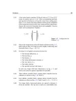
196 Transient and multidimensional heat conduction §5.2
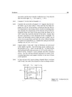
Figure 5.1 A simple
resistance-capacitance circuit.
With six variables in the dimensions J, K, m, and s, only two pi-groups
will appear in the dimensionless function equation.
Θ = fn
hAt
ρcV
= fn
t
T
(5.6)
This is exactly the form of the simple lumped-capacity solution, eqn. (1.22).
Notice, too, that the group t/T can be viewed as
t
T
=
hk(V/A)t
ρc(V/A)
2
k
=
h(V/A)
k
·
αt
(V/A)
2
= Bi Fo (5.7)
Electrical and mechanical analogies to the
lumped-thermal-capacity problem
The term capacitance is adapted from electrical circuit theory to the heat
transfer problem. Therefore, we sketch a simple resistance-capacitance
circuit in Fig. 5.1. The capacitor is initially charged to a voltage, E
o
. When
the switch is suddenly opened, the capacitor discharges through the re-
sistor and the voltage drops according to the relation
dE
dt
+
E
RC
= 0 (5.8)
The solution of eqn. (5.8) with the i.c. E(t = 0) = E
o
is
E = E
o
e
−t/RC
(5.9)
and the current can be computed from Ohm’s law, once E(t) is known.
I =
E
R
(5.10)
Normally, in a heat conduction problem the thermal capacitance,
ρcV, is distributed in space. But when the Biot number is small, T(t)
§5.2 Lumped-capacity solutions 197
is uniform in the body and we can lump the capacitance into a single
circuit element. The thermal resistance is 1/
hA, and the temperature
difference (T − T
∞
) is analogous to E(t). Thus, the thermal response,
analogous to eqn. (5.9), is [see eqn. (1.22)]
T −T
∞
=
(
T
i
−T
∞
)
exp
−
hAt
ρcV
Notice that the electrical time constant, analogous to ρcV/
hA,isRC.
Now consider a slightly more complex system. Figure 5.2 shows a
spring-mass-damper system. The well-known response equation (actu-
ally, a force balance) for this system is
m
What is the mass analogous to?
d
2
x
dt
2
+ c
the damping coefficient is analogous to R or to ρcV
dx
dt
+ k
where k is analogous to 1/C or to hA
x = F(t) (5.11)
A term analogous to mass would arise from electrical inductance, but we
Figure 5.2 A spring-mass-damper
system with a forcing function.
did not include it in the electrical circuit. Mass has the effect of carrying
the system beyond its final equilibrium point. Thus, in an underdamped
mechanical system, we might obtain the sort of response shown in Fig. 5.3
if we specified the velocity at x = 0 and provided no forcing function.
Electrical inductance provides a similar effect. But the Second Law of
Thermodynamics does not permit temperatures to overshoot their equi-
librium values spontaneously. There are no physical elements analogous
to mass or inductance in thermal systems.
198 Transient and multidimensional heat conduction §5.2
Figure 5.3 Response of an unforced
spring-mass-damper system with an
initial velocity.
Next, consider another mechanical element that does have a ther-
mal analogy—namely, the forcing function, F. We consider a (massless)
spring-damper system with a forcing function F that probably is time-
dependent, and we ask: “What might a thermal forcing function look
like?”
Lumped-capacity solution with a variable ambient temperature
To answer the preceding question, let us suddenly immerse an object at
a temperature T = T
i
, with Bi 1, into a cool bath whose temperature is
rising as T
∞
(t) = T
i
+bt, where T
i
and b are constants. Then eqn. (1.20)
becomes
d(T −T
i
)
dt
=−
T −T
∞
T
=−
T −T
i
−bt
T
where we have arbitrarily subtracted T
i
under the differential. Then
d(T −T
i
)
dt
+
T −T
i
T
=
bt
T
(5.12)
To solve eqn. (5.12) we must first recall that the general solution of
a linear ordinary differential equation with constant coefficients is equal
to the sum of any particular integral of the complete equation and the
general solution of the homogeneous equation. We know the latter; it
is T − T
i
= (constant) exp(−t/T ). A particular integral of the complete
equation can often be formed by guessing solutions and trying them in
the complete equation. Here we discover that
T −T
i
= bt − bT
§5.2 Lumped-capacity solutions 199
satisfies eqn. (5.12). Thus, the general solution of eqn. (5.12)is
T −T
i
= C
1
e
−t/T
+b(t − T ) (5.13)
The solution for arbitrary variations of T
∞
(t) is given in Problem 5.52
(see also Problems 5.3, 5.53, and 5.54).
Example 5.1
The flow rates of hot and cold water are regulated into a mixing cham-
ber. We measure the temperature of the water as it leaves, using a
thermometer with a time constant, T . On a particular day, the sys-
tem started with cold water at T = T
i
in the mixing chamber. Then
hot water is added in such a way that the outflow temperature rises
linearly, as shown in Fig. 5.4, with T
exit flow
= T
i
+ bt. How will the
thermometer report the temperature variation?
Solution. The initial condition in eqn. (5.13), which describes this
process, is T −T
i
= 0att = 0. Substituting eqn. (5.13) in the i.c., we
get
0 = C
1
−bT so C
1
= bT
and the response equation is
T −(T
i
+bt) = bT
e
−t/T
−1
(5.14)
This result is graphically shown in Fig. 5.4. Notice that the ther-
mometer reading reflects a transient portion, bT e
−t/T
, which decays
for a few time constants and then can be neglected, and a steady
portion, T
i
+b(t −T ), which persists thereafter. When the steady re-
sponse is established, the thermometer follows the bath with a tem-
perature lag of bT . This constant error is reduced when either T or
the rate of temperature increase, b, is reduced.
Second-order lumped-capacity systems
Now we look at situations in which two lumped-thermal-capacity systems
are connected in series. Such an arrangement is shown in Fig. 5.5. Heat is
transferred through two slabs with an interfacial resistance, h
−1
c
between
them. We shall require that h
c
L
1
/k
1
,h
c
L
2
/k
2
, and hL
2
/k
2
are all much
200 Transient and multidimensional heat conduction §5.2
Figure 5.4 Response of a thermometer to a linearly increasing
ambient temperature.
less than unity so that it will be legitimate to lump the thermal capaci-
tance of each slab. The differential equations dictating the temperature
response of each slab are then
slab 1 : −(ρcV)
1
dT
1
dt
= h
c
A(T
1
−T
2
) (5.15)
slab 2 : −(ρcV)
2
dT
2
dt
=
hA(T
2
−T
∞
) −h
c
A(T
1
−T
2
) (5.16)
and the initial conditions on the temperatures T
1
and T
2
are
T
1
(t = 0) = T
2
(t = 0) = T
i
(5.17)
We next identify two time constants for this problem:
1
T
1
≡ (ρcV)
1
h
c
A and T
2
≡ (ρcV)
2
hA
Then eqn. (5.15) becomes
T
2
= T
1
dT
1
dt
+T
1
(5.18)
1
Notice that we could also have used (ρcV)
2
/h
c
A for T
2
since both h
c
and h act on
slab 2. The choice is arbitrary.
§5.2 Lumped-capacity solutions 201
Figure 5.5 Two slabs conducting in series through an interfa-
cial resistance.
which we substitute in eqn. (5.16)toget
T
1
dT
1
dt
+T
1
−T
∞
+
h
c
h
T
1
dT
1
dt
= T
1
T
2
d
2
T
1
dt
2
−T
2
dT
1
dt
or
d
2
T
1
dt
2
+
1
T
1
+
1
T
2
+
h
c
hT
2
≡b
dT
1
dt
+
T
1
−T
∞
T
1
T
2
c(T
1
−T
∞
)
= 0 (5.19a)
if we call T
1
−T
∞
≡ θ, then eqn. (5.19a) can be written as
d
2
θ
dt
2
+b
dθ
dt
+cθ = 0 (5.19b)
Thus we have reduced the pair of first-order equations, eqn. (5.15) and
eqn. (5.16), to a single second-order equation, eqn. (5.19b).
The general solution of eqn. (5.19b) is obtained by guessing a solution
of the form θ = C
1
e
Dt
. Substitution of this guess into eqn. (5.19b) gives
D
2
+bD +c = 0 (5.20)
from which we find that D =−(b/2) ±
(b/2)
2
−c. This gives us two
values of D, from which we can get two exponential solutions. By adding
202 Transient and multidimensional heat conduction §5.2
them together, we form a general solution:
θ = C
1
exp
−
b
2
+
b
2
2
−c
t +C
2
exp
−
b
2
−
b
2
2
−c
t
(5.21)
To solve for the two constants we first substitute eqn. (5.21) in the
first of i.c.’s (5.17) and get
T
i
−T
∞
= θ
i
= C
1
+C
2
(5.22)
The second i.c. can be put into terms of T
1
with the help of eqn. (5.15):
−
dT
1
dt
t=0
=
h
c
A
(ρcV)
1
(T
1
−T
2
)
t=0
= 0
We substitute eqn. (5.21) in this and obtain
0 =
−
b
2
+
b
2
2
−c
C
1
+
−
b
2
−
b
2
2
−c
C
2
= θ
i
−C
1
so
C
1
=−θ
i
−b/2 −
(b/2)
2
−c
2
(b/2)
2
−c
and
C
2
= θ
i
−b/2 +
(b/2)
2
−c
2
(b/2)
2
−c
So we obtain at last:
T
1
−T
∞
T
i
−T
∞
≡
θ
θ
i
=
b/2 +
(b/2)
2
−c
2
(b/2)
2
−c
exp
−
b
2
+
b
2
2
−c
t
+
−b/2 +
(b/2)
2
−c
2
(b/2)
2
−c
exp
−
b
2
−
b
2
2
−c
t
(5.23)
This is a pretty complicated result—all the more complicated when
we remember that b involves three algebraic terms [recall eqn. (5.19a)].
Yet there is nothing very sophisticated about it; it is easy to understand.
A system involving three capacitances in series would similarly yield a
third-order equation of correspondingly higher complexity, and so forth.
§5.3 Transient conduction in a one-dimensional slab 203
Figure 5.6 The transient cooling of a
slab; ξ = (x/L) +1.
5.3 Transient conduction in a one-dimensional slab
We next extend consideration to heat flow in bodies whose internal re-
sistance is significant—to situations in which the lumped capacitance
assumption is no longer appropriate. When the temperature within, say,
a one-dimensional body varies with position as well as time, we must
solve the heat diffusion equation for T(x,t). We shall do this somewhat
complicated task for the simplest case and then look at the results of
such calculations in other situations.
A simple slab, shown in Fig. 5.6, is initially at a temperature T
i
. The
temperature of the surface of the slab is suddenly changed to T
i
, and we
wish to calculate the interior temperature profile as a function of time.
The heat conduction equation is
∂
2
T
∂x
2
=
1
α
∂T
∂t
(5.24)
with the following b.c.’s and i.c.:
T(−L, t > 0) = T (L, t > 0) = T
1
and T(x,t = 0) = T
i
(5.25)
In fully dimensionless form, eqn. (5.24) and eqn. (5.25) are
∂
2
Θ
∂ξ
2
=
∂Θ
∂Fo
(5.26)
204 Transient and multidimensional heat conduction §5.3
and
Θ(0, Fo) = Θ(2, Fo) = 0 and Θ(ξ, 0) = 1 (5.27)
where we have nondimensionalized the problem in accordance with eqn.
(5.4), using Θ ≡ (T − T
1
)/(T
i
− T
1
) and Fo ≡ αt/L
2
; but for convenience
in solving the equation, we have set ξ equal to (x/L) +1 instead of x/L.
The general solution of eqn. (5.26) may be found using the separation
of variables technique described in Sect. 4.2, leading to the dimensionless
form of eqn. (4.11):
Θ = e
−
ˆ
λ
2
Fo
G sin(
ˆ
λξ) +E cos(
ˆ
λξ)
(5.28)
Direct nondimensionalization of eqn. (4.11) would show that
ˆ
λ ≡ λL,
since λ had units of (length)
−1
. The solution therefore appears to have
introduced a fourth dimensionless group,
ˆ
λ. This needs explanation. The
number λ, which was introduced in the separation-of-variables process,
is called an eigenvalue.
2
In the present problem,
ˆ
λ = λL will turn out to
be a number—or rather a sequence of numbers—that is independent of
system parameters.
Substituting the general solution, eqn. (5.28), in the first b.c. gives
0 = e
−
ˆ
λ
2
Fo
(0 +E) so E = 0
and substituting it in the second yields
0 = e
−
ˆ
λ
2
Fo
G sin 2
ˆ
λ
so either G = 0
or
2
ˆ
λ = 2
ˆ
λ
n
= nπ, n = 0, 1, 2,
In the second case, we are presented with two choices. The first,
G = 0, would give Θ ≡ 0 in all situations, so that the initial condition
could never be accommodated. (This is what mathematicians call a trivial
solution.) The second choice,
ˆ
λ
n
= nπ/2, actually yields a string of
solutions, each of the form
Θ = G
n
e
−n
2
π
2
Fo/4
sin
nπ
2
ξ
(5.29)
2
The word eigenvalue is a curious hybrid of the German term eigenwert and its
English translation, characteristic value.
§5.3 Transient conduction in a one-dimensional slab 205
where G
n
is the constant appropriate to the nth one of these solutions.
We still face the problem that none of eqns. (5.29) will fit the initial
condition, Θ(ξ, 0) = 1. To get around this, we remember that the sum of
any number of solutions of a linear differential equation is also a solution.
Then we write
Θ =
∞
n=1
G
n
e
−n
2
π
2
Fo/4
sin
n
π
2
ξ
(5.30)
where we drop n = 0 since it gives zero contribution to the series. And
we arrive, at last, at the problem of choosing the G
n
’s so that eqn. (5.30)
will fit the initial condition.
Θ
(
ξ,0
)
=
∞
n=1
G
n
sin
n
π
2
ξ
= 1 (5.31)
The problem of picking the values of G
n
that will make this equation
true is called “making a Fourier series expansion” of the function f(ξ) =
1. We shall not pursue strategies for making Fourier series expansions
in any general way. Instead, we merely show how to accomplish the task
for the particular problem at hand. We begin with a mathematical trick.
We multiply eqn. (5.31)bysin(mπ/2), where m may or may not equal
n, and we integrate the result between ξ = 0 and 2.
2
0
sin
mπ
2
ξ
dξ =
∞
n=1
G
n
2
0
sin
mπ
2
ξ
sin
nπ
2
ξ
dξ (5.32)
(The interchange of summation and integration turns out to be legitimate,
although we have not proved, here, that it is.
3
) With the help of a table
of integrals, we find that
2
0
sin
mπ
2
ξ
sin
nπ
2
ξ
dξ =
0 for n ≠ m
1 for n = m
Thus, when we complete the integration of eqn. (5.32), we get
−
2
mπ
cos
mπ
2
ξ
2
0
=
∞
n=1
G
n
×
0 for n ≠ m
1 for n = m
3
What is normally required is that the series in eqn. (5.31)beuniformly convergent.
206 Transient and multidimensional heat conduction §5.3
This reduces to
−
2
mπ
(−1)
n
−1
= G
n
so
G
n
=
4
nπ
where n is an odd number
Substituting this result into eqn. (5.30), we finally obtain the solution to
the problem:
Θ
(
ξ,Fo
)
=
4
π
∞
n=odd
1
n
e
−(nπ/2)
2
Fo
sin
nπ
2
ξ
(5.33)
Equation (5.33) admits a very nice simplification for large time (or at
large Fo). Suppose that we wish to evaluate Θ at the outer center of the
slab—at x = 0orξ = 1. Then
Θ
(
0, Fo
)
=
4
π
×
exp
−
π
2
2
Fo
= 0.085 at Fo = 1
= 0.781 at Fo = 0.1
= 0.976 at Fo = 0.01
−
1
3
exp
−
3π
2
2
Fo
10
−10
at Fo = 1
= 0.036 at Fo = 0.1
= 0.267 at Fo = 0.01
+
1
5
exp
−
5π
2
2
Fo
10
−27
at Fo = 1
= 0.0004 at Fo = 0.1
= 0.108 at Fo = 0.01
+···
Thus for values of Fo somewhat greater than 0.1, only the first term in
the series need be used in the solution (except at points very close to the
boundaries). We discuss these one-term solutions in Sect. 5.5. Before we
move to this matter, let us see what happens to the preceding problem
if the slab is subjected to b.c.’s of the third kind.
Suppose that the walls of the slab had been cooled by symmetrical
convection such that the b.c.’s were
h(T
∞
−T)
x=−L
=−k
∂T
∂x
x=−L
and h(T −T
∞
)
x=L
=−k
∂T
∂x
x=L
or in dimensionless form, using Θ ≡ (T −T
∞
)/(T
i
−T
∞
) and ξ = (x/L)+1,
−Θ
ξ=0
=−
1
Bi
∂Θ
∂ξ
ξ=0
and
∂Θ
∂ξ
ξ=1
= 0
§5.3 Transient conduction in a one-dimensional slab 207
Table 5.1 Terms of series solutions for slabs, cylinders, and
spheres. J
0
and J
1
are Bessel functions of the first kind.
A
n
f
n
Equation for
ˆ
λ
n
Slab
2 sin
ˆ
λ
n
ˆ
λ
n
+sin
ˆ
λ
n
cos
ˆ
λ
n
cos
ˆ
λ
n
x
L
cot
ˆ
λ
n
=
ˆ
λ
n
Bi
L
Cylinder
2 J
1
(
ˆ
λ
n
)
ˆ
λ
n
J
2
0
(
ˆ
λ
n
) +J
2
1
(
ˆ
λ
n
)
J
0
ˆ
λ
n
r
r
o
ˆ
λ
n
J
1
(
ˆ
λ
n
) = Bi
r
o
J
0
(
ˆ
λ
n
)
Sphere
2
sin
ˆ
λ
n
−
ˆ
λ
n
cos
ˆ
λ
n
ˆ
λ
n
−sin
ˆ
λ
n
cos
ˆ
λ
n
r
o
ˆ
λ
n
r
sin
ˆ
λ
n
r
r
o
ˆ
λ
n
cot
ˆ
λ
n
= 1 − Bi
r
o
The solution is somewhat harder to find than eqn. (5.33) was, but the
result is
4
Θ =
∞
n=1
exp
−
ˆ
λ
2
n
Fo
2 sin
ˆ
λ
n
cos[
ˆ
λ
n
(ξ −1)]
ˆ
λ
n
+sin
ˆ
λ
n
cos
ˆ
λ
n
(5.34)
where the values of
ˆ
λ
n
are given as a function of n and Bi = hL/k by the
transcendental equation
cot
ˆ
λ
n
=
ˆ
λ
n
Bi
(5.35)
The successive positive roots of this equation, which are
ˆ
λ
n
=
ˆ
λ
1
,
ˆ
λ
2
,
ˆ
λ
3
, , depend upon Bi. Thus, Θ = fn(ξ, Fo, Bi), as we would expect. This
result, although more complicated than the result for b.c.’s of the first
kind, still reduces to a single term for Fo 0.2.
Similar series solutions can be constructed for cylinders and spheres
that are convectively cooled at their outer surface, r = r
o
. The solutions
for slab, cylinders, and spheres all have the form
Θ =
T −T
∞
T
i
−T
∞
=
∞
n=1
A
n
exp
−
ˆ
λ
2
n
Fo
f
n
(5.36)
where the coefficients A
n
, the functions f
n
, and the equations for the
dimensionless eigenvalues
ˆ
λ
n
are given in Table 5.1.
4
See, for example, [5.1, §2.3.4] or [5.2, §3.4.3] for details of this calculation.
208 Transient and multidimensional heat conduction §5.4
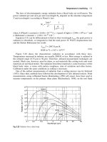
5.4 Temperature-response charts
Figure 5.7 is a graphical presentation of eqn. (5.34) for 0 Fo 1.5 and
for six x-planes in the slab. (Remember that the x-coordinate goes from
zero in the center to L on the boundary, while ξ goes from 0 up to 2 in
the preceding solution.)
Notice that, with the exception of points for which 1/Bi < 0.25 on
the outside boundary, the curves are all straight lines when Fo 0.2.
Since the coordinates are semilogarithmic, this portion of the graph cor-
responds to the lead term—the only term that retains any importance—
in eqn. (5.34). When we take the logarithm of the one-term version of
eqn. (5.34), the result is
ln Θ ln
2 sin
ˆ
λ
1
cos[
ˆ
λ
1
(ξ −1)]
ˆ
λ
1
+sin
ˆ
λ
1
cos
ˆ
λ
1
Θ-intercept at Fo = 0of
the straight portion of
the curve
−
ˆ
λ
2
1
Fo
slope of the
straight portion
of the curve
If Fo is greater than 1.5, the following options are then available to us for
solving the problem:
• Extrapolate the given curves using a straightedge.
• Evaluate Θ using the first term of eqn. (5.34), as discussed in Sect. 5.5.
• If Bi is small, use a lumped-capacity result.
Figure 5.8 and Fig. 5.9 are similar graphs for cylinders and spheres.
Everything that we have said in general about Fig. 5.7 is also true for
these graphs. They were simply calculated from different solutions, and
the numerical values on them are somewhat different. These charts are
from [5.3, Chap. 5], although such charts are often called Heisler charts,
after a collection of related charts subsequently published by Heisler
[5.4].
Another useful kind of chart derivable from eqn. (5.34) is one that
gives heat removal from a body up to a time of interest:
t
0
Qdt=−
⌠
⌡
t
0
kA
∂T
∂x
surface
dt
=−
⌠
⌡
Fo
0
kA
T
i
−T
∞
L
∂Θ
∂ξ
surface
L
2
α
dFo
Figure 5.7 The transient temperature distribution in a slab at six positions: x/L = 0 is the center,
x/L = 1 is one outside boundary.
209
Figure 5.8 The transient temperature distribution in a long cylinder of radius r
o
at six positions:
r/r
o
= 0 is the centerline; r/r
o
= 1 is the outside boundary.
210
Figure 5.9 The transient temperature distribution in a sphere of radius r
o
at six positions: r/r
o
= 0
is the center; r/r
o
= 1 is the outside boundary.
211
212 Transient and multidimensional heat conduction §5.4
Dividing this by the total energy of the body above T
∞
, we get a quan-
tity, Φ, which approaches unity as t →∞and the energy is all transferred
to the surroundings:
Φ ≡
t
0
Qdt
ρcV(T
i
−T
∞
)
=−
⌠
⌡
Fo
0
∂Θ
∂ξ
surface
dFo (5.37)
where the volume, V = AL. Substituting the appropriate temperature
distribution [e.g., eqn. (5.34) for a slab] in eqn. (5.37), we obtain Φ(Fo, Bi)
in the form of an infinite series
Φ
(
Fo, Bi
)
= 1 −
∞
n=1
D
n
exp
−
ˆ
λ
2
n
Fo
(5.38)
The coefficients D
n
are different functions of
ˆ
λ
n
— and thus of Bi — for
slabs, cylinders, and spheres (e.g., for a slab D
n
= A
n
sin
ˆ
λ
n
ˆ
λ
n
). These
functions can be used to plot Φ(Fo, Bi) once and for all. Such curves are
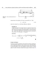
given in Fig. 5.10.
The quantity Φ has a close relationship to the mean temperature of
a body at any time,
T(t). Specifically, the energy lost as heat by time t
determines the difference between the initial temperature and the mean
temperature at time t
t
0
Qdt=
U(0) −U(t)
= ρcV
T
i
−T(t)
. (5.39)
Thus, if we define
Θ as follows, we find the relationship of T(t) to Φ
Θ ≡
T(t)−T
∞
T
i
−T
∞
= 1 −
t
0
Q(t) dt
ρcV(T
i
−T
∞
)
= 1 −Φ. (5.40)
Example 5.2
A dozen approximately spherical apples, 10 cm in diameter are taken
from a 30
◦
C environment and laid out on a rack in a refrigerator at
5
◦
C. They have approximately the same physical properties as water,
and
h is approximately 6 W/m
2
K as the result of natural convection.
What will be the temperature of the centers of the apples after 1 hr?
How long will it take to bring the centers to 10
◦
C? How much heat
will the refrigerator have to carry away to get the centers to 10
◦
C?
Figure 5.10 The heat removal from suddenly-cooled bodies as
a function of
h and time.
213