(McGraw-Hill) (Instructors Manual) Electric Machinery Fundamentals 4th Edition Episode 1 Part 8 ppt
Bạn đang xem bản rút gọn của tài liệu. Xem và tải ngay bản đầy đủ của tài liệu tại đây (601.43 KB, 20 trang )
135
5-21. Assume that the generator is connected to a 480-V infinite bus, and that its field current has been adjusted
so that it is supplying rated power and power factor to the bus. You may ignore the armature resistance
A
R
when answering the following questions.
(a) What would happen to the real and reactive power supplied by this generator if the field flux (and
therefore
A
E ) is reduced by 5%.
(b) Plot the real power supplied by this generator as a function of the flux
φ
as the flux is varied from 75%
to 100% of the flux at rated conditions.
(c) Plot the reactive power supplied by this generator as a function of the flux
φ
as the flux is varied from
75% to 100% of the flux at rated conditions.
(d) Plot the line current supplied by this generator as a function of the flux
φ
as the flux is varied from 75%
to 100% of the flux at rated conditions.
S
OLUTION
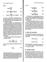
(a) If the field flux in increase by 5%, nothing would happen to the real power. The reactive power
supplied would increase as shown below.
V
φ
E
A
1
jX
S
I
A
Q
sys
Q
G
Q
2
Q
1
E
A
2
I
A
2
I
A
1
V
T
Q
∝
I
sin
θ
A
The reactive power
136
(b) If armature resistance is ignored, the power supplied to the bus will not change as flux is varied.
Therefore, the plot of real power versus flux is
(c) If armature resistance is ignored, the internal generated voltage
A
E
will increase as flux increases,
but the quantity
δ
sin
A
E will remain constant. Therefore, the voltage for any flux can be found from the
expression
Ar
r
A
EE
=
φ
φ
and the angle
δ
for any
A
E can be found from the expression
=
−
r
A
Ar
E
E
δδ
sinsin
1
where
φ
is the flux in the machine,
r
φ
is the flux at rated conditions,
Ar
E
is the magnitude of the internal
generated voltage at rated conditions, and
r
δ
is the angle of the internal generated voltage at rated
conditions. From this information, we can calculate
A
I for any given load from equation
S
A
A
jX
φ
VE
I
−
=
and the resulting reactive power from the equation
θ
φ
sin 3
A
IVQ =
where
θ
is the impedance angle, which is the negative of the current angle. Ignoring
A
R
, the internal
generated voltage at rated conditions is
ASA
jX IVE +=
φ
()( )
277 0 0.899 565.3 31.8 A
A
j=∠°+ Ω ∠− °E
137
695 38.4 V
A
=∠°E
so
V 461=
Ar
E
and
°= 5.27
r
δ
. A MATLAB program that calculates the reactive power supplied
voltage as a function of flux is shown below:
% M-file: prob5_21c.m
% M-file to calculate and plot the reactive power
% supplied to an infinite bus as flux is varied from
% 75% to 100% of the flux at rated conditions.
% Define values for this generator
flux_ratio = 0.90:0.01:1.00; % Flux ratio
Ear = 695; % Ea at full flux
dr = 38.4 * pi/180; % Torque ang at full flux
Vp = 277; % Phase voltage
Xs = 0.899; % Xs (ohms)
% Calculate Ea for each flux
Ea = flux_ratio * Ear;
% Calculate delta for each flux
d = asin( Ear ./ Ea .* sin(dr));
% Calculate Ia for each flux
Ea = Ea .* ( cos(d) + j.*sin(d) );
Ia = ( Ea - Vp ) ./ (j*Xs);
% Calculate reactive power for each flux
theta = -atan2(imag(Ia),real(Ia));
Q = 3 .* Vp .* abs(Ia) .* sin(theta);
% Plot the power supplied versus flux
figure(1);
plot(flux_ratio,Q/1000,'b-','LineWidth',2.0);
title ('\bfReactive power versus flux');
xlabel ('\bfFlux (% of full-load flux)');
ylabel ('\bf\itQ\rm\bf (kVAR)');
grid on;
hold off;
138
When this program is executed, the plot of reactive power versus flux is
(d) The program in part (c) of this program calculated
A
I as a function of flux. A MATLAB program
that plots the magnitude of this current as a function of flux is shown below:
% M-file: prob5_21d.m
% M-file to calculate and plot the armature current
% supplied to an infinite bus as flux is varied from
% 75% to 100% of the flux at rated conditions.
% Define values for this generator
flux_ratio = 0.75:0.01:1.00; % Flux ratio
Ear = 695; % Ea at full flux
dr = 38.4 * pi/180; % Torque ang at full flux
Vp = 277; % Phase voltage
Xs = 0.899; % Xs (ohms)
% Calculate Ea for each flux
Ea = flux_ratio * Ear;
% Calculate delta for each flux
d = asin( Ear ./ Ea .* sin(dr));
% Calculate Ia for each flux
Ea = Ea .* ( cos(d) + j.*sin(d) );
Ia = ( Ea - Vp ) ./ (j*Xs);
% Plot the armature current versus flux
figure(1);
plot(flux_ratio,abs(Ia),'b-','LineWidth',2.0);
title ('\bfArmature current versus flux');
xlabel ('\bfFlux (% of full-load flux)');
ylabel ('\bf\itI_{A}\rm\bf (A)');
grid on;
139
hold off;
When this program is executed, the plot of armature current versus flux is
5-22. A 100-MVA 12.5-kV 0.85-PF-lagging 50-Hz two-pole Y-connected synchronous generator has a per-unit
synchronous reactance of 1.1 and a per-unit armature resistance of 0.012.
(a) What are its synchronous reactance and armature resistance in ohms?
(b) What is the magnitude of the internal generated voltage
E
A
at the rated conditions? What is its torque
angle
δ
at these conditions?
(c) Ignoring losses in this generator, what torque must be applied to its shaft by the prime mover at full
load?
S
OLUTION
The base phase voltage of this generator is
,base
12,500/ 3 7217 VV
φ
==. Therefore, the base
impedance of the generator is
()
2
2
,base
base
base
3
37217 V
1.56
100,000,000 VA
V
Z
S
φ
== =Ω
(a) The generator impedance in ohms are:
()( )
0.012 1.56 0.0187
A
R =Ω=Ω
()( )
1.1 1.56 1.716
S
X =Ω=Ω
(b) The rated armature current is
()
100 MVA
4619 A
3 3 12.5 kV
AL
T
S
II
V
== = =
The power factor is 0.8 lagging, so
4619 36.87 A
A
=∠− °I
. Therefore, the internal generated voltage is
AAASA
RjX
φ
=+ +EV I I
140
()()()()
7217 0 0.0187 4619 36.87 A 1.716 4619 36.87 A
A
j=∠°+ Ω ∠− °+ Ω ∠− °E
13,590 27.6 V
A
=∠°E
Therefore, the magnitude of the internal generated voltage
A
E = 13,590 V, and the torque angle
δ
= 23
°
.
(c) Ignoring losses, the input power would equal the output power. Since
()( )
OUT
0.85 100 MVA 85 MWP ==
and
()
sync
120 50 Hz
120
3000 r/min
2
e
f
n
P
== =
the applied torque would be
()()()
app ind
85,000,000 W
270,000 N m
3000 r/min 2 rad/r 1 min/60 s
ττ
π
== = ⋅
5-23. A three-phase Y-connected synchronous generator is rated 120 MVA, 13.2 kV, 0.8 PF lagging, and 60 Hz.
Its synchronous reactance is 0.9 Ω, and its resistance may be ignored.
(a) What is its voltage regulation?
(b) What would the voltage and apparent power rating of this generator be if it were operated at 50 Hz
with the same armature and field losses as it had at 60 Hz?
(c) What would the voltage regulation of the generator be at 50 Hz?
S
OLUTION
(a) The rated armature current is
()
120 MVA
5249 A
3 3 13.2 kV
AL
T
S
II
V
== = =
The power factor is 0.8 lagging, so 5249 36.87 A
A
=∠− °I . The phase voltage is 13.2 kV / 3 = 7621
V. Therefore, the internal generated voltage is
AAASA
RjX
φ
=+ +EV I I
()( )
7621 0 0.9 5249 36.87 A
A
j=∠°+ Ω ∠− °E
11,120 19.9 V
A
=∠°E
The resulting voltage regulation is
11,120 7621
VR 100% 45.9%
7621
−
=×=
(b) If the generator is to be operated at 50 Hz with the same armature and field losses as at 60 Hz (so
that the windings do not overheat), then its armature and field currents must not change. Since the voltage
of the generator is directly proportional to the speed of the generator, the voltage rating (and hence the
apparent power rating) of the generator will be reduced by a factor of 5/6.
()
,rated
5
13.2 kV 11.0 kV
6
T
V ==
()
rated
5
120 MVA 100 MVA
6
S ==
141
Also, the synchronous reactance will be reduced by a factor of 5/6.
()
5
0.9 0.75
6
S
X =Ω=Ω
(c) At 50 Hz rated conditions, the armature current would be
()
100 MVA
5247 A
3 3 11.0 kV
AL
T
S
II
V
== = =
The power factor is 0.8 lagging, so 5247 36.87 A
A
=∠− °I . The phase voltage is 11.0 kV / 3 = 6351
V. Therefore, the internal generated voltage is
AAASA
RjX
φ
=+ +EV I I
()( )
6351 0 0.75 5247 36.87 A
A
j=∠°+ Ω ∠− °E
9264 19.9 V
A
=∠°E
The resulting voltage regulation is
9264 6351
VR 100% 45.9%
6351
−
=×=
Because voltage, apparent power, and synchronous reactance all scale linearly with frequency, the voltage
regulation at 50 Hz is the same as that at 60 Hz. Note that this is not quite true, if the armature resistance
A
R is included, since
A
R does not scale with frequency in the same fashion as the other terms.
5-24. Two identical 600-kVA 480-V synchronous generators are connected in parallel to supply a load. The
prime movers of the two generators happen to have different speed droop characteristics. When the field
currents of the two generators are equal, one delivers 400 A at 0.9 PF lagging, while the other delivers 300
A at 0.72 PF lagging.
(a) What are the real power and the reactive power supplied by each generator to the load?
(b) What is the overall power factor of the load?
(c) In what direction must the field current on each generator be adjusted in order for them to operate at the
same power factor?
S
OLUTION
(a) The real and reactive powers are
()()()
1
3 cos 3 480 V 400 A 0.9 299 kW
TL
PVI
θ
== =
(
)
(
)
(
)
1
1
3 sin 3 480 V 400 A sin cos 0.9 145 kVAR
TL
QVI
θ
−
== =
(
)
(
)
(
)
2
3 cos 3 480 V 200 A 0.72 120 kW
TL
PVI
θ
== =
(
)
(
)
(
)
1
2
3 sin 3 480 V 200 A sin cos 0.72 115 kVAR
TL
QVI
θ
−
== =
(b) The overall power factor can be found from the total real and reactive power supplied to the load.
TOT 1 2
299 kW 120 kW 419 kWPPP=+= + =
TOT 1 2
145 kVAR 115 kVAR 260 kVARQQQ=+= + =
The overall power factor is
142
1
TOT
TOT
PF cos tan 0.850 lagging
Q
P
−
==
(c) The field current of generator 1 should be increased, and the field current of generator 2 should be
simultaneously decreased.
5-25. A generating station for a power system consists of four 120-MVA 15-kV 0.85-PF-lagging synchronous
generators with identical speed droop characteristics operating in parallel. The governors on the
generators’ prime movers are adjusted to produce a 3-Hz drop from no load to full load. Three of these
generators are each supplying a steady 75 MW at a frequency of 60 Hz, while the fourth generator (called
the swing generator) handles all incremental load changes on the system while maintaining the system's
frequency at 60 Hz.
(a) At a given instant, the total system loads are 260 MW at a frequency of 60 Hz. What are the no-load
frequencies of each of the system’s generators?
(b) If the system load rises to 290 MW and the generator’s governor set points do not change, what will the
new system frequency be?
(c) To what frequency must the no-load frequency of the swing generator be adjusted in order to restore the
system frequency to 60 Hz?
(d) If the system is operating at the conditions described in part (c), what would happen if the swing
generator were tripped off the line (disconnected from the power line)?
S
OLUTION
(a) The full-load power of these generators is
()()
MW10285.0 MVA120 = and the droop from no-
load to full-load is 3 Hz. Therefore, the slope of the power-frequency curve for these four generators is
102 MW
34 MW/Hz
3 Hz
P
s ==
If generators 1, 2, and 3 are supplying 75 MW each, then generator 4 must be supplying 35 MW. The no-
load frequency of the first three generators is
()
1 1 nl1 sysP
Ps f f=−
(
)
()
nl1
75 MW 34 MW/Hz 60 Hzf=−
nl1
62.21 Hzf =
The no-load frequency of the fourth generator is
()
4 4 nl4 sysP
Ps f f=−
()
()
nl1
35 MW 34 MW/Hz 60 Hzf=−
Hz03.61
nl1
=f
(b) The setpoints of generators 1, 2, 3, and 4 do not change, so the new system frequency will be
()()()()
LOAD 1 nl1 sys 2 nl2 sys 3 nl3 sys 4 nl4 sysPP P P
Psffsffsffsff=−+−+−+−
()
()
()
()
()
()
()
()
sys sys sys sys
290 MW 34 62.21 34 62.21 34 62.21 34 61.03ffff=−+−+−+−
sys
8.529 247.66 4 f=−
143
sys
59.78 Hzf =
(c) The governor setpoints of the swing generator must be increased until the system frequency rises back
to 60 Hz. At 60 Hz, the other three generators will be supplying 75 MW each, so the swing generator must
supply 290 MW – 3(75 MW) = 65 MW at 60 Hz. Therefore, the swing generator’s setpoints must be set
to
()
4 4 nl4 sysP
Ps f f=−
(
)
()
nl1
65 MW 34 MW/Hz 60 Hzf=−
nl1
61.91 Hzf =
(d) If the swing generator trips off the line, the other three generators would have to supply all 290 MW
of the load. Therefore, the system frequency will become
()()()
LOAD 1 nl1 sys 2 nl2 sys 3 nl3 sysPP P
P sff sff sff=−+−+−
(
)
()
(
)
()
(
)
()
sys sys sys
290 MW 34 62.21 34 62.21 34 62.21fff=−+−+−
sys
8.529 186.63 3 f=−
sys
59.37 Hzf =
Each generator will supply 96.7 MW to the loads.
5-26. Suppose that you were an engineer planning a new electric co-generation facility for a plant with excess
process steam. You have a choice of either two 10 MW turbine-generators or a single 20 MW turbine
generator. What would be the advantages and disadvantages of each choice?
S
OLUTION
A single 20 MW generator will probably be cheaper and more efficient than two 10 MW
generators, but if the 20 MW generator goes down all 20 MW of generation would be lost at once. If two
10 MW generators are chosen, one of them could go down for maintenance and some power could still be
generated.
5-27. A 25-MVA three-phase 13.8-kV two-pole 60-Hz synchronous generator was tested by the open-circuit test,
and its air-gap voltage was extrapolated with the following results:
Open-circuit test
Field current, A 320 365 380 475 570
Line voltage, kV 13.0 13.8 14.1 15.2 16.0
Extrapolated air-gap voltage, kV 15.4 17.5 18.3 22.8 27.4
The short-circuit test was then performed with the following results:
Short-circuit test
Field current, A 320 365 380 475 570
Armature current, A 1040 1190 1240 1550 1885
The armature resistance is 0.24 Ω per phase.
(a) Find the unsaturated synchronous reactance of this generator in ohms per phase and in per-unit.
(b) Find the approximate saturated synchronous reactance
X
S
at a field current of 380 A. Express the
answer both in ohms per phase and in per-unit.
144
(c) Find the approximate saturated synchronous reactance at a field current of 475 A. Express the answer
both in ohms per phase and in per-unit.
(d) Find the short-circuit ratio for this generator.
S
OLUTION
(a) The unsaturated synchronous reactance of this generator is the same at any field current, so we will
look at it at a field current of 380 A. The extrapolated air-gap voltage at this point is 18.3 kV, and the
short-circuit current is 1240 A. Since this generator is Y-connected, the phase voltage is
18.3 kV/ 3 10,566 V V
φ
==
and the armature current is 1240 A
A
I = . Therefore, the unsaturated
synchronous reactance is
10,566 V
8.52
1240 A
Su
X ==Ω
The base impedance of this generator is
()
2
2
,base
base
base
3
3 7967 V
7.62
25,000,000 VA
V
Z
S
φ
== =Ω
Therefore, the per-unit unsaturated synchronous reactance is
,pu
8.52
1.12
7.62
Su
X
Ω
==
Ω
(b) The saturated synchronous reactance at a field current of 380 A can be found from the OCC and the
SCC. The OCC voltage at
F
I = 380 A is 14.1 kV, and the short-circuit current is 1240 A. Since this
generator is Y-connected, the corresponding phase voltage is
14.1 kV/ 3 8141 V V
φ
== and the armature
current is 1240 A
A
I = . Therefore, the saturated synchronous reactance is
8141 V
6.57
1240 A
Su
X ==Ω
and the per-unit unsaturated synchronous reactance is
,pu
6.57
0.862
7.62
Su
X
Ω
==
Ω
(c) The saturated synchronous reactance at a field current of 475 A can be found from the OCC and the
SCC. The OCC voltage at
F
I = 475 A is 15.2 kV, and the short-circuit current is 1550 A. Since this
generator is Y-connected, the corresponding phase voltage is
15.2 kV/ 3 8776 V V
φ
==
and the armature
current is 1550 A
A
I = . Therefore, the saturated synchronous reactance is
8776 V
5.66
1550 A
Su
X ==Ω
and the per-unit unsaturated synchronous reactance is
,pu
5.66
0.743
7.62
Su
X
Ω
==
Ω
(d) The rated voltage of this generator is 13.8 kV, which requires a field current of 365 A. The rated line
and armature current of this generator is
145
()
25 MVA
1046 A
3 13.8 kV
L
I ==
The field current required to produce a short-circuit current of 10465 A is about 320 A. Therefore, the
short-circuit ratio of this generator is
365 A
SCR 1.14
320 A
==
5-28. A 20-MVA 12.2-kV 0.8-PF-lagging Y-connected synchronous generator has a negligible armature
resistance and a synchronous reactance of 1.1 per-unit. The generator is connected in parallel with a 60-Hz
12.2-kV infinite bus that is capable of supplying or consuming any amount of real or reactive power with
no change in frequency or terminal voltage.
(a) What is the synchronous reactance of the generator in ohms?
(b) What is the internal generated voltage
E
A
of this generator under rated conditions?
(c) What is the armature current
I
A
in this machine at rated conditions?
(d) Suppose that the generator is initially operating at rated conditions. If the internal generated voltage
E
A
is decreased by 5 percent, what will the new armature current I
A
be?
(e) Repeat part (d) for 10, 15, 20, and 25 percent reductions in
E
A
.
(f) Plot the magnitude of the armature current
I
A
as a function of E
A
. (You may wish to use MATLAB
to create this plot.)
S
OLUTION
(a) The rated phase voltage of this generator is 12.2 kV /
3
= 7044 V. The base impedance of this
generator is
()
2
2
,base
base
base
3
37044 V
7.44
20,000,000 VA
V
Z
S
φ
== =Ω
Therefore,
0 (negligible)
A
R ≈Ω
()( )
1.1 7.44 8.18
S
X =Ω=Ω
(b) The rated armature current is
()
20 MVA
946 A
3 3 12.2 kV
AL
T
S
II
V
== = =
The power factor is 0.8 lagging, so
946 36.87 A
A
=∠− °I
. Therefore, the internal generated voltage is
AAASA
RjX
φ
=+ +EV I I
()( )
7044 0 8.18 946 36.87 A
A
j=∠°+ Ω∠− °E
13,230 27.9 V
A
=∠°E
(c) From the above calculations,
946 36.87 A
A
=∠− °I
.
146
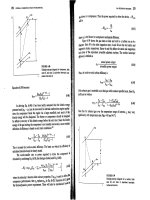
(d) If
A
E is decreased by 5%, the armature current will change as shown below. Note that the infinite
bus will keep
φ
V and
m
ω
constant. Also, since the prime mover hasn’t changed, the power supplied by the
generator will be constant.
V
φ
E
A
1
jX
S
I
A
E
A
2
I
A
2
I
A
1
Q
∝
I
sin
θ
A
3
sin constant
A
S
VE
P
X
φ
δ
==, so
11 22
sin sin
AA
EE
δδ
=
With a 5% decrease,
2
12,570 V
A
E = , and
11
1
22
2
13,230 V
sin sin sin sin 27.9 29.5
12,570 V
A
A
E
E
δδ
−−
== °=°
Therefore, the new armature current is
2
12,570 29.5 7044 0
894 32.2 A
8.18
A
A
S
jX j
φ
−
∠°− ∠°
== =∠−°
EV
I
(e) Repeating part (d):
With a
10% decrease,
2
11, 907 V
A
E = , and
11
1
22
2
13,230 V
sin sin sin sin 27.9 31.3
11,907 V
A
A
E
E
δδ
−−
== °=°
Therefore, the new armature current is
2
11, 907 31.3 7044 0
848 26.8 A
8.18
A
A
S
jX j
φ
−
∠°− ∠°
== =∠−°
EV
I
With a
15% decrease,
2
11, 246 V
A
E = , and
11
1
22
2
13,230 V
sin sin sin sin 27.9 33.4
11,246 V
A
A
E
E
δδ
−−
== °=°
Therefore, the new armature current is
2
11,246 33.4 7044 0
809 20.7 A
8.18
A
A
S
jX j
φ
−
∠°− ∠°
== =∠−°
EV
I
With a
20% decrease,
2
10,584 V
A
E = , and
11
1
22
2
13,230 V
sin sin sin sin 27.9 35.8
10,584 V
A
A
E
E
δδ
−−
== °=°
Therefore, the new armature current is
147
2
10,584 35.8 7044 0
780 14.0 A
8.18
A
A
S
jX j
φ
−
∠°− ∠°
== =∠−°
EV
I
With a
25% decrease,
2
9,923 V
A
E =
, and
11
1
22
2
13,230 V
sin sin sin sin 27.9 38.6
9,923 V
A
A
E
E
δδ
−−
== °=°
Therefore, the new armature current is
2
9,923 38.6 7044 0
762 6.6 A
8.18
A
A
S
jX j
φ
−
∠°− ∠°
== =∠−°
EV
I
(f) A MATLAB program to plot the magnitude of the armature current
A
I as a function of
A
E is shown
below.
% M-file: prob5_28f.m
% M-file to calculate and plot the armature current
% supplied to an infinite bus as Ea is varied.
% Define values for this generator
Ea = (0.65:0.01:1.00)*13230; % Ea
Vp = 7044; % Phase voltage
d1 = 27.9*pi/180; % torque angle at full Ea
Xs = 8.18; % Xs (ohms)
% Calculate delta for each Ea
d = asin( 13230 ./ Ea .* sin(d1));
% Calculate Ia for each flux
Ea = Ea .* ( cos(d) + j.*sin(d) );
Ia = ( Ea - Vp ) ./ (j*Xs);
% Plot the armature current versus Ea
figure(1);
plot(abs(Ea)/1000,abs(Ia),'b-','LineWidth',2.0);
title ('\bfArmature current versus \itE_{A}\rm');
xlabel ('\bf\itE_{A}\rm\bf (kV)');
ylabel ('\bf\itI_{A}\rm\bf (A)');
grid on;
hold off;
148
The resulting plot is shown below:
149
Chapter 6:
Synchronous Motors
6-1. A 480-V, 60 Hz, four-pole synchronous motor draws 50 A from the line at unity power factor and full
load. Assuming that the motor is lossless, answer the following questions:
(a) What is the output torque of this motor? Express the answer both in newton-meters and in pound-feet.
(b) What must be done to change the power factor to 0.8 leading? Explain your answer, using phasor
diagrams.
(c) What will the magnitude of the line current be if the power factor is adjusted to 0.8 leading?
S
OLUTION
(a) If this motor is assumed lossless, then the input power is equal to the output power. The input power
to this motor is
()()()
IN
3 cos 3 480 V 50 A 1.0 41.6 kW
TL
PVI
θ
== =
The output torque would be
()
OUT
LOAD
41.6 kW
221 N m
1 min 2 rad
1800 r/min
60 s 1 r
m
P
τ
π
ω
== = ⋅
In English units,
(
)
(
)
()
OUT
LOAD
7.04 41.6 kW
7.04
163 lb ft
1800 r/min
m
P
n
τ
== =⋅
(b) To change the motor’s power factor to 0.8 leading, its field current must be increased. Since the
power supplied to the load is independent of the field current level, an increase in field current increases
A
E
while keeping the distance
δ
sin
A
E
constant. This increase in
A
E
changes the angle of the current
A
I , eventually causing it to reach a power factor of 0.8 leading.
V
φ
E
A
1
jX
S
I
A
E
A
2
I
A
2
I
A
1
Q
∝
I
sin
θ
A
}
∝
P
}
∝
P
(c) The magnitude of the line current will be
()()
41.6 kW
62.5 A
3 PF 3 480 V 0.8
L
T
P
I
V
== =
6-2. A 480-V, 60 Hz, 400-hp 0.8-PF-leading six-pole
∆
-connected synchronous motor has a synchronous
reactance of 1.1 Ω and negligible armature resistance. Ignore its friction, windage, and core losses for the
purposes of this problem.
150
(a) If this motor is initially supplying 400 hp at 0.8 PF lagging, what are the magnitudes and angles of
E
A
and
I
A
?
(b) How much torque is this motor producing? What is the torque angle
δ
? How near is this value to the
maximum possible induced torque of the motor for this field current setting?
(c) If
E
A
is increased by 15 percent, what is the new magnitude of the armature current? What is the
motor’s new power factor?
(d) Calculate and plot the motor’s V-curve for this load condition.
S
OLUTION
(a) If losses are being ignored, the output power is equal to the input power, so the input power will be
()( )
IN
400 hp 746 W/hp 298.4 kWP ==
This situation is shown in the phasor diagram below:
V
φ
E
A
jX
S
I
A
I
A
The line current flow under these circumstances is
()()
298.4 kW
449 A
3 PF 3 480 V 0.8
L
T
P
I
V
== =
Because the motor is
∆
-connected, the corresponding phase current is
449 / 3 259 A
A
I ==
. The angle of
the current is
()
1
cos 0.80 36.87
−
−=−°, so 259 36.87 A
A
=∠− °I . The internal generated voltage
A
E is
ASA
jX
φ
=−EV I
()()( )
480 0 V 1.1 259 36.87 A 384 36.4 V
A
j=∠°− Ω ∠− °=∠−°E
(b) This motor has 6 poles and an electrical frequency of 60 Hz, so its rotation speed is
m
n = 1200 r/min.
The induced torque is
()
OUT
ind
298.4 kW
2375 N m
1 min 2 rad
1200 r/min
60 s 1 r
m
P
τ
π
ω
== = ⋅
The maximum possible induced torque for the motor at this field setting is
()()
()
()
ind,max
3
3 480 V 384 V
4000 N m
1 min 2 rad
1200 r/min 1.1
60 s 1 r
A
mS
VE
X
φ
τ
π
ω
== =⋅
Ω
(c) If the magnitude of the internal generated voltage
A
E
is increased by 15%, the new torque angle can
be found from the fact that
constantsin =∝ PE
A
δ
.
()
21
1.15 1.15 384 V 441.6 V
AA
EE== =
151
()
11
1
21
2
384 V
sin sin sin sin 36.4 31.1
441.6 V
A
A
E
E
δδ
−−
== −°=−°
The new armature current is
2
2
480 0 V 441.6 31.1 V
227 24.1 A
1.1
A
A
S
jX j
φ
−
∠° − ∠− °
== =∠−°
Ω
VE
I
The magnitude of the armature current is 227 A, and the power factor is cos (-24.1°) = 0.913 lagging.
(d) A MATLAB program to calculate and plot the motor’s V-curve is shown below:
% M-file: prob6_2d.m
% M-file create a plot of armature current versus Ea
% for the synchronous motor of Problem 6-2.
% Initialize values
Ea = (1:0.01:1.70)*384; % Magnitude of Ea volts
Ear = 384; % Reference Ea
deltar = -36.4 * pi/180; % Reference torque angle
Xs = 1.1; % Synchronous reactance
Vp = 480; % Phase voltage at 0 degrees
Ear = Ear * (cos(deltar) + j * sin(deltar));
% Calculate delta2
delta2 = asin ( abs(Ear) ./ abs(Ea) .* sin(deltar) );
% Calculate the phasor Ea
Ea = Ea .* (cos(delta2) + j .* sin(delta2));
% Calculate Ia
Ia = ( Vp - Ea ) / ( j * Xs);
% Plot the v-curve
figure(1);
plot(abs(Ea),abs(Ia),'b','Linewidth',2.0);
xlabel('\bf\itE_{A}\rm\bf (V)');
ylabel('\bf\itI_{A}\rm\bf (A)');
title ('\bfSynchronous Motor V-Curve');
grid on;
152
The resulting plot is shown below
350 400 450 500 550 600 650 700
200
210
220
230
240
250
260
E
A
(V)
I
A
(A)
Synchronous Motor V-Curve
6-3. A 2300-V 1000-hp 0.8-PF leading 60-Hz two-pole Y-connected synchronous motor has a synchronous
reactance of 2.8 Ω and an armature resistance of 0.4 Ω. At 60 Hz, its friction and windage losses are 24
kW, and its core losses are 18 kW. The field circuit has a dc voltage of 200 V, and the maximum
I
F
is 10
A. The open-circuit characteristic of this motor is shown in Figure P6-1. Answer the following questions
about the motor, assuming that it is being supplied by an infinite bus.
(a) How much field current would be required to make this machine operate at unity power factor when
supplying full load?
(b) What is the motor’s efficiency at full load and unity power factor?
(c) If the field current were increased by 5 percent, what would the new value of the armature current be?
What would the new power factor be? How much reactive power is being consumed or supplied by the
motor?
(d) What is the maximum torque this machine is theoretically capable of supplying at unity power factor?
At 0.8 PF leading?
Note: An electronic version of this open circuit characteristic can be found in file
p61_occ.dat, which can be used with MATLAB programs. Column 1
contains field current in amps, and column 2 contains open-circuit terminal
voltage in volts.
153
S
OLUTION
(a) At full load, the input power to the motor is
CUcoremechOUTIN
PPPPP +++=
We can’t know the copper losses until the armature current is known, so we will find the input power and
armature current ignoring that term, and then correct the input power after we know it.
()( )
IN
1000 hp 746 W/hp 24 kW 18 kW 788 kWP =++=
Therefore, the line and phase current at unity power factor is
()()
788 kW
198 A
3 PF 3 2300 V 1.0
AL
T
P
II
V
== = =
The copper losses due to a current of 198 A are
()()
2
2
CU
3 3 198 A 0.4 47.0 kW
AA
PIR== Ω=
Therefore, a better estimate of the input power at full load is
()( )
IN
1000 hp 746 W/hp 24 kW 18 kW 47 kW 835 kWP =+++=
and a better estimate of the line and phase current at unity power factor is
154
()()
835 kW
210 A
3 PF 3 2300 V 1.0
AL
T
P
II
V
== = =
The phasor diagram of this motor operating a unity power factor is shown below:
jX
S
I
A
V
φ
I
A
E
A
I
A
R
A
The phase voltage of this motor is 2300 /
3
= 1328 V. The required internal generated voltage is
AAASA
RjX
φ
=− −EV I I
()( )()( )
1328 0 V 0.4 210 0 A 2.8 210 0 A
A
j=∠°−Ω∠°− Ω∠°E
1376 25.3 V
A
=∠−°E
This internal generated voltage corresponds to a terminal voltage of
()
3 1376 2383 V=
. This voltage
would require a field current of 4.6 A.
(b) The motor’s efficiency at full load and unity power factor is
OUT
IN
746 kW
100% 100% 89.3%
835 kW
P
P
η
=× = × =
(c) To solve this problem, we will temporarily ignore the effects of the armature resistance
A
R
. If
A
R
is
ignored, then
δ
sin
A
E is directly proportional to the power supplied by the motor. Since the power
supplied by the motor does not change when
F
I is changed, this quantity will be a constant.
If the field current is increased by 5%, then the new field current will be 4.83 A, and the new value of
the open-circuit terminal voltage will be 2450 V. The new value of
A
E
will be 2450 V /
3
= 1415 V.
Therefore, the new torque angle
δ
will be
()
11
1
21
2
1376 V
sin sin sin sin 25.3 24.6
1415 V
A
A
E
E
δδ
−−
== −°=−°
Therefore, the new armature current will be
1328 0 V 1415 -25.3 V
214.5 3.5 A
0.4 2.8
A
A
AS
RjX j
φ
−
∠° − ∠ °
== =∠°
++Ω
VE
I
The new current is about the same as before, but the phase angle has become positive. The new power
factor is cos 3.5
°
= 0.998 leading, and the reactive power supplied by the motor is
(
)
(
)
(
)
3 sin 3 2300 V 214.5 A sin 3.5 52.2 kVAR
TL
QVI
θ
== °=
(d) The maximum torque possible at unity power factor (ignoring the effects of
A
R ) is:
(
)
(
)
() ()
ind,max
3
3 1328 V 1376 V
5193 N m
1 min 2 rad
3600 r/min 2.8
60 s 1 r
A
mS
VE
X
φ
τ
π
ω
== =⋅
Ω