Báo cáo lâm nghiệp: "A contribution to the resistance of combined plywood materials to abrasion" potx
Bạn đang xem bản rút gọn của tài liệu. Xem và tải ngay bản đầy đủ của tài liệu tại đây (217 KB, 9 trang )
J. FOR. SCI., 54, 2008 (1): 31–39 31
JOURNAL OF FOREST SCIENCE, 54, 2008 (1): 31–39
e surface of materials with glass fibre shows
specific properties. Before the actual assessment
of abrasion resistance, the methodology of testing
the abrasion resistance of combined water-proof
plywood materials with the phenol-formaldehyde
foil surface finish without and with fibreglass was
designed. Water-proof plywood is a large-area
material glued by a phenol-formaldehyde adhesive.
It is manufactured by the combination of beech,
birch and spruce veneers. Water-proof plywoods are
manufactured in two versions:
– plywoods with double-faced surface finish with a
smooth foil;
– plywoods with the one side finished with a smooth
foil and the other side with a foil subject to antislip
treatment.
Lateral edges are treated with coating from effects
of moisture. Plywoods treated with a phenol-for-
maldehyde foil are used where there is an increased
risk of damage to the surface by abrasion, e.g.
shelves, work platforms, sports floors, work tables,
formwork, surface of lorry beds and railway wagons.
anks to their resistance to water the plywoods can
also be used in industries with higher moisture or at
places where they will be subject to weather effects
(K, H 2003).
All these properties are affected by several fac-
tors: type and composition of resin, amount of resin
deposit, quality and weight of bearing paper, special
admixtures, shape of the pressing plate surface etc.
(S 1995).
In addition to static functions, combined plywood
materials also show various special functions, for
example thermal and insulation ones. By the combina-
tion of these two requirements a material originates
which is more suitable as against the use of separate
materials (H, K 2007). ese advantages
consist particularly in price factors but also in the
A contribution to the resistance of combined plywood
materials to abrasion
P. K, J. H
Faculty of Forestry and Wood Technology, Mendel University of Agriculture and Forestry in Brno,
Brno, Czech Republic
ABSTRACT: e aim of the paper was to propose the methodology of testing the abrasion resistance of combined
water-proof plywood materials with the phenol-formaldehyde foil surface finish and to assess the surface resistance
of a new combined plywood material of a given construction to abrasion. For sheathing, phenol-formaldehyde foils
with the low content of resins were used, which are combined with unwoven and woven glass fibres highly resistant to
mechanical wear. e paper for phenol-formaldehyde foils manufactured of sulphate pulp (basis weight 60 g/m
2
) was
impregnated by a low-molecular resin with the resin deposit 150% DM (dry matter) per paper DM. To evaluate the
newly designed material our testing methodology was prepared in such a way that it will conform to related European
standards. It is completed by the method of sampling and preparation of samples for tests including their acclimation.
According to our proposal, measurements were carried out of selected constructions of water-resistant plied veneer
materials with jackets of various basis weight combined with glass fibres. Data on the abrasion resistance were acquired
which can be considered to be reliable. e values of abrasion resistance were assessed with respect to standards valid
in the EU which determine fields of their use.
Keywords: abrasion resistance; foliated plywood; phenol foil; glass fibre; high-pressure laminate; abrasion; phenol-
formaldehyde resin; Taber abraser
Supported by the Ministry of Education, Youth and Sports of the Czech Republic, Project No. MSM 6215648902 Forest and
Wood.
32 J. FOR. SCI., 54, 2008 (1): 31–39
simplicity of production technology and productivity
of work. Combined plywood materials are manufac-
tured in smaller amounts than plywoods for construc-
tion purposes and the manufacture of formwork.
MATERIAL AND METHODS
Several standards deal with testing the abrasion
resistance of wood-based materials. e particular
methods differ because they examine various types
of surfaces. us, there arise different requirements
for abrasion resistance. e proposed methodology
is based on the DIN 53 799 standard, being however
completed by the procedure of sampling, prepara-
tion and air conditioning of samples in such a way
that a well-arranged and integrated instruction for
standard users will be created. is standard was
used as a starting norm thanks to its high popular-
ity in European manufacturers of plywoods with
foil surface finish, particularly in Germany, which
belongs to leading countries in the manufacture of
plywoods.
Standards ČSN 91 0276 (Furniture. Methods of
Determining the Surface Abrasion Resistance) and
ČSN EN 13329 (Laminated Floor Coverings) were
also taken into account. Members with surface fin-
ish on the basis of reaction-plastic amino resins.
Specifications, requirements, methods of testing,
ČSN EN 438-1 standard (High-pressure Decorative
HPL Laminates. Boards based on reaction-plastics.
Part 1. Introduction and general information) and
ČSN EN 438-2 standard (High-pressure Decorative
HPL Laminates. Boards based on reaction-plastics.
Part 2. Determination of properties).
Products are sampled from the assessed batch
using the method of random sampling. Tests can
be carried out on control samples prepared in the
process of manufacture as well as on samples pre-
pared under laboratory conditions and showing the
same surface as tested products.
To determine the surface properties at least 3 test
specimens are necessary from each of the boards.
e specimens are taken uniformly with respect to
the product dimensions at places where no defect
occurs relating to the surface finish.
e abrasion resistance was tested on combined
seven-ply plywood boards 15 mm thick manufactured
of beech and spruce veneers 1.8 and 3.0 mm thick, re-
spectively. e surface of these boards was treated with
single-layer phenol-formaldehyde foils of basis weight
167 g/m
2
. e amount of the phenol-formaldehyde
resin deposit ranged from 125 to 145 g/m
2
.
Square test specimens of the edge length 100 mm
are cut from the board. In the test specimen cen-
tre, a hole of 65 mm in diameter is bored for the
purpose of fastening to a carrier. e specimen
thickness must range between 0.5 and 5 mm. In
larger thickness, the lower side has to be worked in
parallel with the specimen level (Fig. 2). e speci-
men height has to correspond to requirements of
a testing machine. If the testing machine does not
allow to change the height of pivot points of holding
arms, where abrasive disks are placed in such a way
that the arms will be sufficiently parallel with the
test specimen surface, it is necessary to carry out the
working of the lower side of the test specimen.
e principle of tests
e ability of the board decorative surface layer to
resist abrasion down to the board base is determined
by a test. A rotating test specimen is abraded by the
effect of loaded cylindrical abrasive disks with glued-
on strips of sanding paper. e force of 5.5 ± 0.2 N
acts on each of the abrasive disks. e sanding pa-
per with a self-adhesive layer is glued on the whole
girth of rubber disks. e ends of sanding paper are
trimmed as necessary in such a way that the send-
ing paper will cover the whole circumference of the
rubber disk, however, not being glued crisscross.
Abrasive disks are placed in such a way that their
cylindrical surfaces will be at the same distance from
the axis of rotation of the test specimen, not being
however oriented to it tangentially.
By turning the test specimen abrasive disks rotate
creating a groove of the annulus shape on the test
specimen surface. As the rate of abrasion resistance,
the number of revolutions (speed) of a test specimen
is used to a certain degree of abrasion.
Preparation of test specimens
e test specimen surface is cleaned by rinsing us-
ing an anhydrous organic solvent, e.g. 1,1,1-trichlo-
roethane, which disturbs the test specimen surface.
Samples are visually checked before the beginning of
the test. Defects found are recorded into a protocol.
Before the actual test, samples are acclimatized for
72 hours at least in the environment with air temper-
ature 23 ± 2°C and air relative humidity 50 ± 5%.
Test material and device
Self-adhesive sanding paper of basis weight
70–100 g/m
2
of dust Al
2
O
3
(aluminium oxide) of
grain dimensions which fall through the sieve mesh
100 m, being however caught on the sieve mesh
63 m. Grains have to be distributed on the paper
J. FOR. SCI., 54, 2008 (1): 31–39 33
uniformly. If the sanding paper is not self-adhesive,
a double-sided sticky tape is necessary.
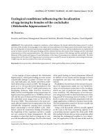
Test instrument. Tests are carried out with an
instrument called Taber abraser (Fig. 1). e test
principle consists in the determination of the resist-
ance of surface layers of tested boards to resist abra-
sion to a base. A rotating test specimen fixed onto
a carrier is worn by the effect of loaded cylindrical
abrasive disks with stuck strips of sanding paper. e
disks are placed in such a way their cylindrical areas
will be at the same distance from the axis of rotation
of the test specimen, not being however oriented
tangentially to it.
By turning the test specimen abrasive disks rotate
creating a groove of the annulus shape on the test
specimen surface. e apparatus consists of a hori-
zontally situated driving disk (7). A test specimen is
fastened (6) onto the disk with a clamping screw (5).
e carrier rotates at a speed of 55 ± 6 rpm. Speed is
taken by a counter. Abrasive disks (3) consist of two
cylindrical rubber wheels 12.7 ± 0.1 mm in width
and 50 mm in diameter, which freely rotate around
the common axis. e cylindrical surface of disks is
covered to a depth of 6 mm with rubber (2) of 50 to
55 IRHD hardness according to ISO 48. Inner ends
of disks are 50 to 55 mm from each other and their
common axis must be at a distance of 20 mm from
the vertical axis of the test specimen holder.
Strips of sanding paper (1) are fixed onto the rub-
ber surface. Exhaust necks (4) are placed 1–2 mm
above the abrasive zone of a test specimen in such
a way that the one neck will be between abrasive
disks and the other diametrically opposite. Centres
of nozzles have to be 77 mm apart and 2 ± 0.5 mm
from the test specimen surface. e exhaust device
suction is 1.5 to 1.6 kPa and the device has to ex-
haust abraded material.
Check test of sanding paper
Two disks are prepared with conditioned unused
sanding paper from the same batch that will be
used for testing. A zinc plate is fixed onto the test
specimen holder, the exhaust device is switched on, a
revolution counter is set to zero, disks are started and
the zinc plate is abraded at 500 rpm. e zinc plate is
cleaned and weighed to the nearest 1 mg. e sand-
ing paper is replaced by new strips of conditioned
Fig. 1. Test device (dimensions in mm)
1 – sanding paper, 2 – rubber, 3 – abrasive
disks, 4 – exhaust necks, 5 – clamping screw,
6 – test specimen, 7 – carrier (a disk carrying a
sample), 8 – supporting and lifting device
Fig. 2. Test specimen (dimensions in mm)
34 J. FOR. SCI., 54, 2008 (1): 31–39
unused sanding paper from the same batch and the
zinc plate is abraded at 500 rpm once more. e
zinc plate is cleaned and reweighed to the nearest
1 mg. A decrease in its weight must be 130 ± 20 mg.
e batch of sanding paper which causes the weight
decrease out of this range must not be used for test-
ing.
Preliminary test
e preliminary test shows if and how often the
sanding paper has to be replaced during testing. e
test specimen is fastened onto a plate being subject
to orientation loading by abrasion at 500 rpm. e
sanding paper and the abrasion image are assessed
at every 25 revolutions (monitoring period). In par-
ticular, it is necessary to follow the uniform course
of abrasion. If the sharpness of abrasion on sanding
paper is smaller after one or several periods of moni-
toring, then the replacement of the sanding paper
subject to the irregular course of abrasion has to be
carried out at a half number of rpm.
Abrasion of the test specimen
e test is carried out immediately after calibra-
tion. Two disks are prepared with conditioned un-
used sanding paper from the same batch that was
approved by the last calibration. e disks are placed
into the apparatus and the revolution counter is set to
zero. e first test specimen is fixed into the holder. It
is necessary to ensure that the test specimen surface
will be flat. e disks are actuated, the exhaust device
is switched on and the test specimen is abraded. e
test specimen is fixed to be flat, abrasive disks are
put on the test specimen, exhaustion is switched
on and turning starts. After every 25 revolutions,
the abrasion of the test specimen and filling of the
sanding paper with abraded material are checked.
e frequency of the sanding paper replacement is
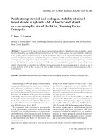
Table 1. e initial and final point of abrasion in samples without glass fibres
Sample
Initial point of abrasion
(rpm)
Final point of abrasion
(rpm)
Mean value (rpm)
1 250 625 437.5
2 225 650 437.5
3 225 650 437.5
4 250 675 462.5
5 250 650 450.0
6 225 625 425.0
7 225 650 437.5
8 250 650 450.0
9 275 750 512.5
10 225 675 450.0
Arithmetic mean (m) 240 660 450.0
Standard deviation (s) 17.48 35.746 24.296
Coefficient of variation V (%) 7.283 5.416 5.399
0
100
200
300
400
500
600
700
800
1 2 3 4 5 6 7 8 9 10
Sample number
Number of rpm
Final point of abrasion Initial point of abrasion
Number of rpm
800
700
600
500
400
300
200
100
0
1 2 3 4 5 6 7 8 9 10
Sample number
Final point of abrasion Initial point of abrasion
Fig. 3. Initial and final points of abrasion in
samples without glass fibres
J. FOR. SCI., 54, 2008 (1): 31–39 35
controlled according to observations from the pre-
liminary test. e sanding paper has to be replaced
in principle after 500 revolutions and after each test.
Tests of this type are carried out until the initial
point of abrasion is achieved when the number of
revolutions is recorded and the test continues until
the final point of abrasion is achieved. e number
of revolutions is recorded again.
e initial point of abrasion occurs when:
– the first disturbance of the printed picture is vis
-
ible in the printed decoration;
– in single-coloured decorations the basis (e.g. pro
-
tective paper, particleboard etc.) is visible.
e final point of abrasion occurs when:
– in printed decorations some 95% of the printed
picture is abraded;
– in single-coloured decorations 95% of the basis (e.g.
protective paper, plywood etc.) shows through.
Abrasive resistance is calculated as follows:
Resistance = (P + K) : 2
where: P – initial value of abrasion,
K – final value of abrasion.
An arithmetic mean from the results of minimally
3 test specimens is taken as “resistance”.
RESULTS
Table 1 shows the initial and final points of abra-
sion in samples without glass fibres inclusive the
arithmetic mean, standard deviation and coefficient
of variation.
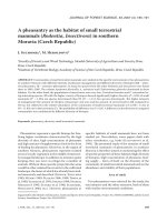
Table 2 shows the initial and final points of
abrasion in samples with glass fibres inclusive the
arithmetic mean, standard deviation and coefficient
of variation.
Table 2. e initial and final point of abrasion in samples with glass fibres
Sample
Initial point of abrasion
(rpm)
Final point of abrasion
(rpm)
Mean value (rpm)
1 275 3,075 1,675.0
2 250 3,125 1,687.5
3 225 3,100 1,662.5
4 250 3,050 1,650.0
5 275 3,500 1,887.5
6 275 3,150 1,712.5
7 275 3,150 1,712.5
8 250 3,025 1,637.5
9 225 4,700 2,462.5
10 225 3,400 1,812.5
Arithmetic mean (m) 252.5 3,327.5 1,790.0
Standard deviation (s) 21.89 506.273 248.803
Coefficient of variation V (%) 8.669 15.215 13.89
Fig. 4. Initial and final points of abrasion in
samples with glass fibres
0
500
1,000
1,500
2,000
2,500
3,000
3,500
4,000
4,500
5,000
1 2 3 4 5 6 7 8 9 10
Sample number
Number of rpm
Final point of abrasion Initial point of abrasion
Number of rpm
5,000
4,500
4,000
3,500
3,000
2,500
2,000
1,500
1,000
500
0
1 2 3 4 5 6 7 8 9 10
Sample number
Final point of abrasion Initial point of abrasion
36 J. FOR. SCI., 54, 2008 (1): 31–39
Table 3. Weights of samples without glass fibres before and after abrasion
Sample Initial weight (g) Final weight (g) Difference in weight (g)
1 132.5857 131.8806 0.7051
2 133.0288 132.2633 0.7655
3 133.1010 132.4042 0.6968
4 133.5700 132.8663 0.7037
5 132.7647 132.0506 0.7141
6 130.9830 130.2733 0.7097
7 133.2222 132.4728 0.7494
8 131.2708 130.4759 0.7949
9 134.7634 133.8736 0.8898
10 134.5973 133.7465 0.8508
Arithmetic mean (m) 132.98869 132.23071 0.75798
Table 4. Weights of samples with glass fibres before and after abrasion
Sample Initial weight (g) Final weight (g) Difference in weight (g)
1 132.3215 129.8397 2.4818
2 132.5481 129.8190 2.7291
3 132.8337 130.2251 2.6086
4 133.2488 130.7923 2.4565
5 132.6613 129.9653 2.6960
6 130.7662 127.9328 2.8334
7 132.9741 129.9868 2.9873
8 130.4613 127.8615 2.5998
9 134.0598 130.5533 3.5065
10 133.9012 130.8834 3.0178
Arithmetic mean (m) 132.5776 129.78592 2.79168
Table 5. Values of abrasion resistance –WISA plywoods
Firm name Sheath weight (g/m
2
) Abrasion value (rpm)
Wisa-Form Spruce 120 300
Betofilm 120 320
Wisa-Form Birch 120 320
Wisa-Wire 145 380
Wisa-Wire 167 450
Wisa-Wire 220 570
Wisa-Form Birch 220 600
Wisa- Hexa Grip 240 630
Wisa-Wire 250 800
Wisa-SP 300 1,070
Wisa-Form Super 400 2,100
Wisa-Trans 500 3,500
Table 3 documents the weights of samples with-
out glass fibres before and after abrasion inclusive
the arithmetic mean.
Table 4 documents the weights of samples with
glass fibres before and after abrasion inclusive the
arithmetic mean.
J. FOR. SCI., 54, 2008 (1): 31–39 37
Table 5 presents a comparison of the values of
abrasion resistance in WISA plywoods.
Table 6 presents a comparison of the values of
abrasion resistance in FINNFOREST plywoods.
Fig. 3 illustrates the initial and final points of
abrasion in samples without glass fibres.
Fig. 4 illustrates the initial and final points of
abrasion in samples with glass fibres.
0
50
100
150
200
250
300
1 2 3 4 5 6 7 8 9 10
Sample number
Number of rpm
Samples without glass fibres Samples with glass fibres
Number of rpm
300
250
200
150
100
50
0
1 2 3 4 5 6 7 8 9 10
Sample number
Samples without glass fibres
Samples with glass fibres
0
500
1,000
1,500
2,000
2,500
3,000
3,500
4,000
4,500
5,000
1 2 3 4 5 6 7 8 9 10
Sample number
Number of rpm
Samples without glass fibress Samples with glass fibress
Number of rpm
1 2 3 4 5 6 7 8 9 10
Sample number
5,000
4,500
4,000
3,500
3,000
2,500
2,000
1,500
1,000
500
0
Samples without glass fibres Samples with glass fibres
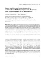
Fig. 6. Comparison of final points of abrasion
in samples with and without glass fibres
Fig. 5. Comparison of initial points of abrasion
in samples with and without glass fibres
Table 6. Values of abrasion resistance – FINNFOREST plywoods
Firm name Sheath weight (g/m
2
) Abrasion value (rpm)
Metsä-Deck 120 350
Metsä-Form 120 350
Metsä-Form 170 600
Metsä-Deck 220 900
Metsä-Form 220 900
Metsä-White 250 500
Metsä-Sp 340 1,300
Metsä-Form 440 2,200
Metsä-Top 440 2,200
Metsä-Floor 500 3,200
Metsä-Diamond 580 3,100
Metsä-Form 660 3,200
Metsä-Top 660 4,100
Metsä-Floor 700 4,300
38 J. FOR. SCI., 54, 2008 (1): 31–39
Fig. 5 compares the initial points of abrasion in
samples with and without glass fibres.
Fig. 6 compares the final points of abrasion in
samples with and without glass fibres.
DISCUSSION
Abrasion resistance was tested on boards of given
thickness and construction. e surface of these
boards was treated with single-layer phenol-formal-
dehyde foils in combination with glass fibres applied
onto the sanded and unsanded underlay surface.
Ten test specimens from each board were meas-
ured. On the basis of measurements, plywoods with
glass fibres show higher abrasion resistance than
plywoods treated with the foil only. It is caused by
the presence of glass fibres. e glass fibre increases
abrasion resistance because its strength is substan-
tially higher than the strength of the foil alone. e
fibre restrains forces induced by an abrader both in
horizontal (rotation) and vertical direction (weight).
After cutting through the upper foil to glass fibres
there occurred a contact of the sanding strip with
glass fibres which resulted in the destruction of the
sanding strip margins. It is caused by a fact that
sharp facets originate on slightly disturbed fibres
which tear the strips.
e plywood which was not equipped with glass
fibres showed quite different values of resistance.
To cut through, a smaller number of rpm and sand-
ing papers, which are not damaged by sharp edges
of disturbed glass fibres, is sufficient. Variations in
measurements can be caused by inaccuracies in
measurements or by the board quality. e quality of
the surface of the last ply of veneers is an important
factor affecting abrasion. If the ply is not prepared
well, the connection of a veneer with a foil is imper-
fect after gluing the foil. It results in a decrease of the
initial point of abrasion when the places with rough
surface are cut through earlier than the well foliated
parts. e uniformity of glue spread below the foil
ranks among other important factors affecting abra-
sion resistance. If the spreads differ markedly, faster
cutting through occurs at the place of the thinner
layer of the adhesive. On the other hand, the thicker
layer of the adhesive is cut through for a longer time.
Of course, it does not mean that higher layers of the
glue are always suitable. e foil quality and kind
are no less important aspects of abrasion resistance.
e values of similar products obtained from for-
eign companies WISA (Finland) and FINNFOREST
(Finland) serve for the purpose of comparison. Face
veneers of these products are of birch except spruce
boards Metsä-Form and Wisa-Form Spruce. All ply-
woods are reground before gluing the foil. Sheathing
is carried out using a single-layer or multi-layer phe-
nol-formaldehyde foils of a basis weight from 120 to
880 g/m
2
. e comparison of values measured at
our workplace and values provided by WISA and
FINNFOREST
manufacturers is rather problematic
because only one tested kind of plywood is available.
Plywoods differ in many factors.
CONCLUSION
e aim of the paper was to propose the method-
ology of testing the abrasion resistance of combined
water-proof plywood materials with the surface
finish of phenol-formaldehyde foils and to assess
abrasion resistance of two different surface treat-
ments applied onto these materials.
The methodology proposed is based on DIN
53 799 standard completed by the procedure of
sampling, preparation and acclimatization of
samples in such a way that a well-arranged and
integrated instruction for common users will be
created. is standard was used as an initial norm
thanks to its high popularity in European manufac-
turers of plywoods with the foil treatment of surface
particularly in Germany, which belongs to leading
countries in the manufacture of plywoods.
According to the methodology proposed by our
workplace we carried out measurements of se-
lected samples of combined plywood boards with
two types of surface foil. Data acquired from our
research results concerning the abrasion resistance
can be considered to be reliable in plywood without
glass fibres, because the coefficient of variation does
not exceed 6%. On the other hand, in the case of us-
ing glass fibres the coefficient of variation increased
to 14%, which was caused particularly by one sam-
ple with the extremely high final point of abrasion.
If this sample were excluded from measurements,
the coefficient of variation would decrease and the
measurement could be considered as reliable.
Boards including glass fibres are (thanks to their
higher point of abrasion) suitable where the higher
load of a construction occurs. On the other hand,
boards without glass fibres are more suitable where
constructions are less loaded, e.g. working boards
of tables.
e comparison of boards in which our meas-
urements were carried out with boards of other
manufacturers is rather complicated because these
products differ in many aspects, e.g. tree species of
the underlying veneer, its treatment, surface design,
and also the procedure of the abrasion resistance
measurement.
J. FOR. SCI., 54, 2008 (1): 31–39 39
Foliated materials are more suitable from eco-
nomic aspects because the wood is utilized more
efficiently. us, by the gradual improvement of
properties of these materials also the field of their
use in various industries is extended.
R ef er en ce s
HRÁZSKÝ J., KRÁL P., 2007
. A contribution to the properties
of combined plywood materials. Journal of Forest Science,
53: 483–490.
KRÁL P., HRÁZSKÝ J.,
2003. Analýza oděruvzdornosti
překližovaných materiálů. Acta Universitatis Agriculturae
et Silviculturae Mendelianae Brunensis, 51: 25–42.
SOINÉ H, 1995. Holzwerkstoffe. Herstellung und Verarbei-
tung. Stuttgart, DRW Verlag: 368.
ČSN EN 438-1, 2005. Vysokotlaké dekorativní lamináty
HPL. Desky na bázi reaktoplastů. Část 1: Úvod a obecné
informace: 12.
ČSN EN 438-2, 2005. Vysokotlaké dekorativní lamináty HPL.
Desky na bázi reaktoplastů. Část 2: Stanovení vlastností: 64.
ČSN 91 0276, 1989. Nábytek. Metoda zjišťování odolnosti
povrchu proti oděru: 8.
ČSN EN 13329, 2006. Laminátové podlahové krytiny. Prvky
s povrchovou úpravou na bázi reaktoplastických aminových
pryskyřic. Specifikace, požadavky, metody zkoušení: 32.
DIN 53 799, 1986. Platten mit dekorativer Oberfläche auf
Aminoplastharzbasis – Prüfung: 14.
Received for publication October 22, 2007
Accepted after corrections November 23, 2007
Příspěvek k odolnosti kombinovaných překližovaných materiálů proti oděru
ABSTRAKT: Předmětem práce bylo posouzení odolnosti povrchu nového kombinovaného překližovaného mate-
riálu stanovené konstrukce. K oplášťování byly použity fenolformaldehydové fólie s nízkým obsahem pryskyřice,
které jsou kombinovány s netkanými a tkanými skleněnými vlákny vysoce odolnými vůči mechanickému opotřebení.
Papír pro fenolformaldehydové fólie vyrobený ze sulfátové buničiny (o plošné hmotnosti 60 g/m
2
) byl impregnován
nízkomolekulární pryskyřicí s nánosem pryskyřice 150 % sušiny na sušinu papíru. Pro hodnocení nově navrženého
materiálu byla naše zkušební metodika vypracována tak, aby odpovídala souvisejícím evropským standardům. Je
doplněna o metodu odběru vzorků a přípravu vzorků ke zkouškám včetně jejich klimatizace. Podle našeho návrhu
byla provedena měření vybraných konstrukcí vodovzdorných vrstvených dýhových materiálů s plášti o různých ploš
-
ných hmotnostech, kombinovaných se skelným vláknem. Byly získány údaje o odolnosti vůči oděru, které můžeme
považovat za spolehlivé. Hodnoty oděruvzdornosti byly posuzovány vzhledem ke standardům platným v Evropské
unii, které stanovují jejich oblasti použití.
Klíčová slova: odolnost proti oděru; fóliované překližky; fenolická fólie; skelné vlákno; vysokotlaký laminát; obru-
šování; fenolformaldehydové pryskyřice; Taber abraser
Corresponding author:
Doc. Dr. Ing. P K, Mendelova zemědělská a lesnická univerzita v Brně, Lesnická a dřevařská fakulta,
Lesnická 37, 613 00 Brno, Česká republika
tel.: + 420 545 134 160, fax: + 420 545 134 157, e-mail: