building a cicso network for windows 2000 phần 6 potx
Bạn đang xem bản rút gọn của tài liệu. Xem và tải ngay bản đầy đủ của tài liệu tại đây (8.81 MB, 60 trang )
274 Chapter 7 • Sizing the Infrastructure for Windows 2000
Figure 7.10 Performance monitor for replication traffic.
Figure 7.11 Replication monitor.
www.syngress.com
71_BCNW2K_07 9/10/00 1:18 PM Page 274
Sizing the Infrastructure for Windows 2000 • Chapter 7 275
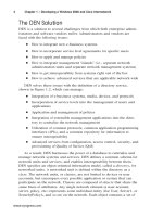
Figure 7.12 Network monitor.
The problem with using the Network monitor lies in the fact that it cap-
tures every packet, and does not filter at the capture level according to the
packet type. What you can do, however, is to set a port for RPC traffic by
configuring the registry key at HKLM\System\CurrentControlSet\Services\
NTDS\Parameters\TCP/IP Port.
Once the port for this is set, you can start the Network monitor. Next
you will need to force replication by opening the Active Directory Sites and
Services console, then right-clicking on the NTDS Settings objects below
each domain controller object and selecting “Replicate Now.” Once replica-
tion has completed, you can review the captured packets for those with the
port number you configured. Those will represent the RPC traffic. If you
have configured a site link to use SMTP traffic, you should also look for
packets using port 25.
Server Placement
Which servers do you place into which sites? Do they have to be domain
controllers? Do they have to be Global Catalog servers? Which sites need
DNS servers or DHCP servers? Where do you put a RAS server for dial up?
Where do you put a RAS server for VPN? What about a branch office with
www.syngress.com
71_BCNW2K_07 9/10/00 1:18 PM Page 275
276 Chapter 7 • Sizing the Infrastructure for Windows 2000
30 users—do they need a domain controller or just a file and print server?
Now server placement seems to be a dilemma—but it is one that is easily
solved.
First, there definitely will be an impact on your network traffic when
you place servers in various sites. The availability of the Active Directory is
directly affected by the placement of various types of servers as well.
Domain Controllers
When you start this exercise, you should already have a site topology plan
for your network. This will be your starting point for determining the place-
ment of domain controllers. In addition to the site topology plan, you
should have your domain/DNS plan, and an understanding of the physical
location of the end-users who will exist in each domain. This will allow you
to determine which domains span which sites, and vice versa, as shown in
Figure 7.13.
Figure 7.13 Domains and sites spanning each other.
It is highly recommended that, for each domain existing within a site,
you also place a domain controller for that domain. There are some excep-
tions to this recommendation—if you have a set of 10 users in a site for
DOMAIN.COM, and you have 287 users in that same site belonging to
ROOT.COM, then you will not need a DC for DOMAIN.COM in that site.
However, if you have 100 users for DOMAIN.COM and 287 users for
ROOT.COM, then you will probably want to include a DC from both
domains.
www.syngress.com
Site 1
Site 2
s4.root.com
s2.sub.tree.com
s1.tree.com
s3.tree.com
Tree.com spans both Site 1 and Site 2.
Site 1 spans tree.com and root.com.
Site 2 spans tree.com and sub.tree.com.
71_BCNW2K_07 9/10/00 1:18 PM Page 276
Sizing the Infrastructure for Windows 2000 • Chapter 7 277
Imagine if you have a large campus network with five domains in a
single site. You would want to put five different DCs in that single site
simply to support authentication traffic. As you can see, the more domains
that exist in a site, the more separate servers you will need. And this is not
counting whether you need separate Global Catalog, DNS, DHCP, or other
servers running in those sites yet.
Once you’ve decided which sites will receive at least one domain con-
troller from the domains in your plan, you need to determine how many
domain controllers total you will want for that domain. This decision will
be based partially on the number of sites that you deem require a domain
controller, and partially on the size and power of the server hardware that
will support the domain controllers. A single-processor Pentium PC with a
4GB hard drive will not support even a fifth as many users as a four-pro-
cessor Pentium III server-class machine with a 40GB RAID array. But you
don’t want to max out your server to start with either; you need to plan to
leave room for growth. You will want to take into account whether your
domain controller will provide other services such as DNS, DHCP, or file
and print services because these services will reduce the capacity of the
domain controller to support the Active Directory services.
So, there is no magic formula regarding the number of users a domain
controller will support. But there is a way of figuring out how many your
domain controller will support. The first thing to do is to look at some
statistics such as those in Table 7.2, and estimate what size servers you
will need for today and for the future. Note that these are averages, and
that there may be some differences in the size of your Active Directory
objects and replication traffic based on the number of attributes you fill
out in each object, whether you include custom attributes, and whether
these attributes are copied to the Global Catalog.
www.syngress.com
Table 7.2 Sizing Statistics
Component Definition Size
Security principal
Nonsecurity
principal
Attributes
User, Group, any object that can be
granted rights to other objects
Organizational Unit, Organization, any
object that is not granted rights to
other objects
Additional attributes added to support
services on the network, such as DNS
3600 bytes
1100 bytes
100 bytes per
attribute
Continued
71_BCNW2K_07 9/10/00 1:18 PM Page 277
278 Chapter 7 • Sizing the Infrastructure for Windows 2000
When you determine the size of your Active Directory storage needs,
usually you can be assured that any standard hard drive will be able to
house even the largest domain partitions. Use the following equation to
estimate your storage needs:
(#Security Principals * 3600 bytes) +
(#Non-security principals * 1100 Bytes) =
Active Directory Size
To ensure that you have enough space for growth, multiply this result
by at least 200 percent or more, depending on your company’s growth over
the last three years.
Active Directory Size * 200% = Minimum DC capacity required
If you have a domain with 200,000 users, 1000 organizational units,
then you can safely estimate your AD database storage needs:
(200,000 * 3600)+(1000 * 1100)= 721100000 Bytes = 687 MB * 200% =
1374 MB = 1.2 GB
Table 7.2 shows that the size of the replication of new objects and
changed attributes turns out to be more expensive than the incremental
storage of that same data on a single DC hard disk. For example, if you
have one DC storing all the objects in a single domain that is the only
domain in its forest, then there is no replication traffic that will interrupt
other network traffic on the wire. (However, you won’t have any redun-
www.syngress.com
Table 7.2 Continued
Component Definition Size
Intrasite replication
of a single user
Intrasite replication
of a single
attribute change
Intersite replication
of a single user
Intersite replication
of a single
attribute
The average amount of replication
traffic generated within a site when
creating a new user account
The average amount of replication
traffic generated within a site when
changing a single attribute on an AD
object
The average amount of replication
traffic generated between sites when
creating a new user account
The average amount of replication
traffic generated between sites when
changing a single attribute
13,000 bytes
4500 bytes
11,000 bytes
4000 bytes
71_BCNW2K_07 9/10/00 1:18 PM Page 278
Sizing the Infrastructure for Windows 2000 • Chapter 7 279
dancy in case that DC fails, so always make certain to have two DCs per
domain.) If you have two domain controllers, then you will have one time
replication for each change on the Active Directory database. If you have
three DCs, then replication will occur twice (from DC1 to DC2, then from
DC2 to DC3) for each update on the Active Directory. Replication is simply
the number of DCs (one, as shown in Figure 7.14). Since hard drive
storage is cheap and bandwidth has a lot of competition for its use by
applications on the network, it is cheaper from a network traffic standpoint
to maintain fewer DCs!
Figure 7.14 Active Directory replication between four DCs.
A DC’s processor utilization increases as the number of users increases
in a domain. Several factors contribute to this phenomenon. The main
issue is not replication or storage, but happens to be the number of users
that log on simultaneously or query the network for resources at the same
time. The differences in processor types that are supported by Windows
2000 are widely varied. Not only are the manufacturers and processor
models variables, but the speed of the processor (MHz) and the supported
bus speed of the motherboard (also in MHz, but different from the processor
speed) are also variables—and these can make all the difference in how
your processor performs. You will need to test your processor in a lab envi-
ronment to determine its maximum simultaneous processing capabilities.
You can test these capabilities using Performance monitor and simulation
www.syngress.com
s4.root.com
s2.sub.tree.com
s3.tree.com
A full ring for replication
traffic is achieved with 3
paths between the 4 DCs.
71_BCNW2K_07 9/10/00 1:18 PM Page 279
280 Chapter 7 • Sizing the Infrastructure for Windows 2000
/benchmarking utilities. (You can find many simulation or benchmarking
utilities on the Internet. One of the largest benchmarking software devel-
opers is ZDNet’s Benchmark Operation, whose Web site is
www.zdnet.com/zdbop/.) But just finding the maximum simultaneous
capacity is not enough; you need to consider the likelihood of that max-
imum capacity. For example, if you have a processor that reaches 99 per-
cent utilization with 1000 simultaneous logons, you will also want to
consider how often 1000 users would log on simultaneously. If 1000
people were to arrive at work at the same time and log on, they would
probably do so within the space of several minutes. If you give them five
minutes, then you would be estimating that your server could support up
to 5000 users in a network before it was maxed out.
Again, the maximum capacity is not the beginning capacity for your
network; you want to make certain to include enough room for growth.
One way to do this is to add domain controllers to the domain. Another
way to do this is to load up on the hardware for your domain controller. If
you think that one processor will just about be sufficient to support your
network, two processors will be better, and four will give that domain con-
troller room for growth for quite a while.
Once you specify how many DCs you need in each domain, compare
that to how many domain controllers you will need to support your sites.
From this comparison, select the number of DCs that is larger. For
example, if you have three sites and intend to place a DC in each, and you
have determined that only two DCs are needed to support the domain’s
users, then you will need three DCs in total. What is nice about this situa-
tion is that you know exactly where each DC will be placed. However, if
you have three sites and you need five DCs to support the domain, then
you must determine where to place the other two DCs. Look at the number
of users in each site. If two of the sites have 200 users each, and the third
site has 7000 users, then the two other DCs should be placed in the site
with 7000 users. This method will ensure that the workload is balanced for
those DCs.
Aside from balancing the workload, redundancy is another issue to
consider when deciding the number of DCs per site. If a WAN link is
untrustworthy (it fails often or is overutilized), you should ensure that the
number of DCs in each site connected to that WAN link is at least two.
Global Catalog Servers
The Global Catalog is required to be available in each site if the Active
Directory forest consists of more than one domain. The multidomain forest is
an important factor. In a single-domain forest, there is no need for a Global
www.syngress.com
71_BCNW2K_07 9/10/00 1:18 PM Page 280
Sizing the Infrastructure for Windows 2000 • Chapter 7 281
Catalog since all resources will be available in the domain partition of the
Active Directory.
The Global Catalog is important for multidomain forests because:
■
It is used during the logon process to determine memberships of
universal groups. If unable to contact a GC server, logon is refused
to ensure that the user had not been denied access to resources
through a universal group membership.
■
It is used for queries of resources that exist outside of a user’s own
domain.
If you have more than one domain, you will want to place at least one
GC server in each site. This will probably not require any extra physical
servers because a GC server is simply an enhanced domain controller, and
will consume only a minor amount of storage and processing power.
Although you will not need as many GC servers as you do DCs, wherever
possible, you should try to ensure that workload is balanced among the
GC servers in a site, and that redundant GC servers are placed in sites
separated by untrustworthy WAN links.
DNS Servers
The Active Directory depends on DNS in order for
■
DCs to contact each other for replication
■
Users to contact DCs to log on to the network
■
Users to contact GCs to execute a query
Without DNS, there is no communication—users can’t log on, and the
Active Directory cannot replicate updates. Because of DNS’s importance,
you should ensure that at least one DNS server exists in each site, and two
should exist in any site that is separated from other DNS servers by
untrustworthy WAN links.
You can install DNS services on the existing DCs in the forest. The DNS
service will consume a minor amount of storage and processing power. It is
recommended that you test the capacity of a DC with additional services
loaded on it when you add DNS and the Global Catalog.
WINS Servers
Windows Internet Naming Service (WINS) is used to map NetBIOS names
to IP addresses. WINS is not necessary to the working domain running in
native mode. You may not need to plan for WINS servers at all, but for
those networks that do need to provide WINS services for downlevel clients,
www.syngress.com
71_BCNW2K_07 9/10/00 1:18 PM Page 281
282 Chapter 7 • Sizing the Infrastructure for Windows 2000
they should be placed in a centrally available network location. You should
have at least two WINS servers on the internetwork for redundancy.
FSMOs
There are five Flexible Single Masters of Operations (FSMOs) that you need
to consider for placement on the network:
■
RID master
■
PDC emulator
■
Domain naming master
■
Infrastructure master
■
Schema master
Relative ID (RID) Master
The RID master is a designated DC. It provides unique relative ID portions
of the SID to other DCs. When those DCs assign SIDs to security princi-
pals (users, groups, or other objects that can be granted rights), the RID
master ensures that the SID is unique. This is especially necessary when
moving an object between domains.
When placing the RID master, you need to consider which DC is most
easily accessible by other DCs in the domain. If you have a hub-and-spoke
formation in your network where there is one main site and the rest of
your sites all connect to it, it is fairly simple to select a DC in that site. If,
however, you have a more complex internetwork with several major sites,
you should still select the site that is most central to all other DCs.
In the case of a downed RID master, where the RID master is not recov-
erable, you will need to change the role to another DC on the internetwork.
This means that you should select a DC to serve as the backup RID master.
Remember that the RID master backup will not automatically happen by
itself; you will need to change the role over manually:
1. Open the Active Directory Users and Computers console.
2. Right-click on the domain.
3. Select Connect to Domain Controller from the menu.
4. Select the DC which you are going to transfer the RID master role
to.
5. Click OK.
6. Right-click on the domain.
7. Select Operations Master from the menu.
www.syngress.com
71_BCNW2K_07 9/10/00 1:18 PM Page 282
Sizing the Infrastructure for Windows 2000 • Chapter 7 283
8. Click the Change button on the RID tab.
9. Click OK.
PDC Emulator
The PDC Emulator does more than act as a backward-compatible PDC in a
mixed mode domain. It still exists in a native mode domain. Overall, the
PDC emulator handles these important functions:
■
Mixed mode PDC authority over Windows NT BDCs
■
Native mode and mixed mode central repository for domain pass-
word changes
■
Native mode and mixed mode central authority for time synchro-
nization
When the domain is in mixed mode, the PDC Emulator is the PDC for
any Windows NT BDCs in the same domain. The PDC Emulator cannot
exist in a domain that has a Windows NT PDC in it, which is why a migra-
tion plan must upgrade the Windows NT PDC first, when retaining the
same domain.
When the domain is in any mode, the PDC Emulator is contacted by
each DC on which a password change has been made, and then stores
that password change. If a user changes his or her password on one DC,
and then attempts to authenticate to another DC that still holds the old
password, the DC first contacts the PDC Emulator to check for a password
change there. In this way, the user’s logon can be accepted.
The PDC Emulator also takes on the role of the time authority for the
domain. All other DCs will synchronize their clocks to the PDC Emulator,
and then serve that time to the time clients in the domain.
The PDC Emulator needs to be highly available to the entire domain,
especially to DCs in its own domain. You will want to place that PDC
Emulator in a location that is central to other DCs and is highly available
to them. Because of the PDC Emulator’s critical nature for password
changes, you will want to give that role to a DC that has fault tolerant
hardware, such as a RAID array or cluster. You will also need to designate
a potential backup PDC Emulator in case the original DC holding that role
fails. To change the role of a DC to a PDC Emulator, follow a nearly iden-
tical process as that of changing the RID master role:
1. Open the Active Directory Users and Computers console.
2. Right-click on the domain.
3. Select Connect to Domain Controller from the menu.
www.syngress.com
71_BCNW2K_07 9/10/00 1:18 PM Page 283
284 Chapter 7 • Sizing the Infrastructure for Windows 2000
4. Select the DC to which you are going to transfer the PDC Emulator
role.
5. Click OK.
6. Right-click on the domain.
7. Select Operations Master from the menu.
8. Click the PDC tab.
9. Click the Change button.
10. Click OK.
Domain Naming Master
There is a single Domain Naming master per Active Directory forest. The
first DC installed is granted this role by default. The Domain Naming
master ensures that the domain namespace is unique within a forest, and
is used each time a domain is added or removed from the forest. The
Domain Naming master must be installed on a Global Catalog server.
When placing the Domain Naming master, you should select a DC
within the root domain (although being a member of the root domain is not
necessarily a requirement, it can enhance performance because of its
Kerberos trust relationships) of the forest that is also a Global Catalog
server. It must be available to each domain in the forest, so this Domain
Naming master’s site must be site-linked or site-link-bridged to every other
site in the forest.
You can change the Domain Naming master through the Active
Directory Domains and Trusts console:
1. Open the Active Directory Domains and Trusts console.
2. Right-click the root.
3. Select Connect to Domain Controller from the menu.
4. Type the name of the DC that will be the new Domain Naming
master (make certain you select a Global Catalog server) and press
Enter.
5. Right-click on the root again.
6. Select Operations Masters from the menu.
7. Click the Change button.
8. Click OK.
www.syngress.com
71_BCNW2K_07 9/10/00 1:18 PM Page 284
Sizing the Infrastructure for Windows 2000 • Chapter 7 285
Infrastructure Master
There is a single Infrastructure master in each domain. It is used to main-
tain a reference to objects in other domains—specifically those objects that
have been moved to other domains, or group members that belong to other
domains.
The Infrastructure master should reside on a DC that is highly avail-
able to the rest of the DCs for that domain. Try to place the server in a
central location for that domain. To change the Infrastructure master role:
1. Open the Active Directory Users and Computers console.
2. Right-click on the domain.
3. Select Connect to Domain Controller from the menu.
4. Select the DC that will be the new Infrastructure master.
5. Click OK.
6. Right-click the domain.
7. Select Operations Masters from the menu.
8. Click the Infrastructure tab.
9. Click the Change Button.
10. Click OK.
Schema Master
There is a single Schema master within an Active Directory forest. It is the
only domain controller on which the schema can be changed. You can
change the Schema master role from one DC to another.
TIP
To make any changes to the schema or the Schema master, you must
install the Windows 2000 Administrative Tools. To do this, use the
Add/Remove Programs icon in the Control Panel, select Windows 2000
Administrative Tools, and click Change. Then install all the administrative
tools.
To start the Active Directory Schema snap-in, click Start and then Run.
Type MMC and press Enter. Click the Console menu and select
Add/Remove Snap-In. Click Add and select the Active Directory Schema.
Click Add, then Close and OK to return to the console window.
www.syngress.com
71_BCNW2K_07 9/10/00 1:18 PM Page 285
286 Chapter 7 • Sizing the Infrastructure for Windows 2000
Because the schema should not be changed often, and because only a
very few persons should ever be granted access to change the schema, the
placement of the Schema master will not affect Active Directory perfor-
mance. You may wish to grant the Schema master role to a DC that is not
easily accessible. To change the Schema master role:
1. Open the Active Directory Schema Manager console.
2. Right-click on the root.
3. Select Change Domain Controller from the menu.
4. Type the name of the new Schema master.
5. Click OK.
6. Right-click on the root.
7. Select Operations Master from the menu.
8. Click the Change button.
9. Click OK.
RAS Servers
Placing a RAS server for dial-up users on the network is a matter of
bringing the server closer to the resources that users need to access. If you
are placing a RAS server for a VPN, then bring the server closer to the WAN
link, from which users will be connecting. In the best of worlds, you will be
able to place that server close to the resources and move the WAN link or
dial-up lines to where that server resides.
DHCP Servers
If you apply static IP addresses to both clients and servers currently, then
you should look into adding DHCP to the network. DHCP will assign IP
addresses to workstations and servers when they authenticate to the net-
work. The addresses can be pooled so that they are efficiently handed out
to workstations on an as-needed basis. If you are currently using DHCP,
then you already know of the benefits that it can bring to your network.
DHCP is important for every network client and server that uses it. A
workstation or a server would not be able to access the network without
receiving an assigned IP address from a DHCP server or being able to con-
tact the DHCP server to renew it.
When you consider the placement of the DHCP servers, you need to
look at the:
www.syngress.com
71_BCNW2K_07 9/10/00 1:18 PM Page 286
Sizing the Infrastructure for Windows 2000 • Chapter 7 287
■
Number of sites
■
Size of the sites
■
Speed and reliability of the WAN links
You will want to place DHCP servers at your main sites, and then place
DHCP servers at any site that is connected to the internetwork via slow or
unreliable WAN links. This does not necessarily mean adding yet another
server to the network; you can install the DHCP service on a Windows
2000 DC, or other Windows 2000 server.
Terminal Services
Terminal Services offer a thin-client solution for applications across the
network. They also have an option of being installed to provide server man-
agement via remote control of the server console. The placement of the
Terminal server depends on the role that the Terminal Service is playing.
If Terminal Services are being added to Windows 2000 servers and
domain controllers in order to provide a method of server management,
then it does not matter where those servers are placed. They should be
placed solely in accordance with the other services that they are providing
on the network.
For example, if Terminal Services are installed on a Windows 2000
server or domain controller in order to provide an application to thin-
clients, then the server should be placed close to the application data
source. You see, a Terminal server is the middle tier of a three-tier system,
as shown in Figure 7.15. As the middle tier, the Terminal server acts as a
client to network server applications. The application client must be
installed on the Terminal server. Workstations are installed with a
Terminal server client, with which they access the Terminal server, take
remote control of a session, and then use the application client to access
other network servers.
Figure 7.15 Terminal Services as the middle tier in a three-tier system.
www.syngress.com
Data Server
Hosts database for Terminal Services
Terminal Server
Client to Data Server
Host to Terminal Client
Terminal Client
Client to Terminal Services
Runs database client via remote control
Tier 1 Tier 3Tier 2
71_BCNW2K_07 9/10/00 1:18 PM Page 287
288 Chapter 7 • Sizing the Infrastructure for Windows 2000
Terminal Services should be placed close to servers that provide data to
the applications. For example, if a Terminal server was going to be used for
access to a SQL application, then the Terminal server and the SQL server
should both be placed on the same network segment, or two segments that
are well connected. This rule does not prove true for the workstations since
they use a thin-client application (which uses very little network band-
width, for example) to take control of a Terminal server. Workstations can
be placed anywhere on a network relative to the Terminal server.
When you size a Terminal server itself, you need to consider the
number of simultaneous users. A single Pentium II processor generally can
provide sessions for about 20 to 25 users. Therefore if you want to provide
Terminal Services for 50 simultaneous users, you would need at least two
or more processors. (Simultaneous users are not the total number of users
that are allowed to use the server, but are the total number of users that
would actually use the server at the exact same time.)
The number of simultaneous users also governs the amount of RAM.
First, you would allocate about 256MB of RAM for the base operating
system. Although Windows 2000 will operate with around 128MB of RAM,
you will want to double it to 256MB to handle all the services that will run
on the server. Then you will want to add 8MB RAM for each simultaneous
user. This means that if you have 50 simultaneous users, you will add
another 400MB RAM to your total. This gives us a total of 656MB RAM,
but since no machine has that specific amount, you will round it up to the
next level or more. So if the server supports RAM in 256MB increments,
you would install 768MB or RAM of more. (More RAM cannot hurt your
server’s performance.)
Infrastructure Components
The infrastructure is everything that sits between a client workstation and
a Windows 2000 server, including the wiring, hubs, switches, routers, and
gateways. The Active Directory can be optimized to work well on many
existing internetworks. Generally, it can use the existing infrastructure
components. Even so, the internetwork may perform better if it is also
optimized to work with the Active Directory in return.
The goal of sizing the infrastructure is to maximize the availability of
services while minimizing the bandwidth that those same services con-
sume. One of the challenges that businesses face today is an increasing
use of the Internet to perform daily business procedures. This leads to
competition for bandwidth from all end-points to the Internet connection
(or connections) that exist on the internetwork. When reviewing infrastruc-
ture components, you need to take this growing bandwidth consumption
www.syngress.com
71_BCNW2K_07 9/10/00 1:18 PM Page 288
Sizing the Infrastructure for Windows 2000 • Chapter 7 289
into account and plan for managing it, whether through cache engines,
proxies, or increased bandwidth availability.
Table 7.3 is a list of the components that you should review. If the
questions that you ask reveal that any component currently is not suffi-
cient or will not be sufficient in the future, then you should upgrade that
component.
www.syngress.com
Table 7.3 Infrastructure Components
Component Analysis
Cabling
Cabling
WAN Links
WAN Links
WAN Links
LAN Links
LAN Links
LAN Links
Routers/Bridges
Routers/Bridges
Network Interface
Cards (NICs)
Is the cabling stable, or does it perform with faults?
Can the cabling support faster Physical/Data Link
protocols?
Is there available bandwidth on the existing WAN
links?
Are there redundant WAN links in case of a failure?
Will a WAN link support additional bandwidth con-
sumption given an average of 5% compounded
growth in consumption month over month over the
next year?
Is the local LAN segment experiencing excessive delays
or, in the case of Ethernet, excessive collisions?
Are hubs used for shared network segment access?
Are switches used with microsegmentation (each
workstation receiving its own port) or do switches
connect multiple shared access hubs?
Does the infrastructure support all the protocols
required—TCP/IP, DNS, Dynamic DNS, DHCP, Quality of
Service (QoS), IPSec?
Does the infrastructure support the needs for voice
and video data?
Are all network interfaces compatible with Windows
2000?
71_BCNW2K_07 9/10/00 1:18 PM Page 289
290 Chapter 7 • Sizing the Infrastructure for Windows 2000
WARNING
An administrator who creates a large number of objects over a short
period of time can cause a denial of service for end users. What happens
in this case is that massive replication occurs within the domain and
throughout the Global Catalog for the forest—especially within a site
where replication takes place upon demand rather than on a schedule.
The replication within a site is not compressed and therefore can take up
most of the network bandwidth. Then, when the replicated traffic
reaches a Global Catalog server, it must use its processing power to
handle the changes to its database. As a result, a user who accesses the
network can be denied access because the network is busy transmitting
replication traffic. Or a user who attempts to access a Global Catalog
server at the time that it is processing these changes will be denied
access to the Active Directory or to the server’s resources.
Quality of Service
If you intend to deploy Quality of Service (QoS), you must ensure that the
internetwork will support it. Many older versions of routers will not recog-
nize a QoS packet. When this happens, the packet is handled just like any
other packet, and if the header is stripped and rebuilt in order to pass that
packet from one segment to another, then all remaining infrastructure
components will treat that packet without any priority whatsoever. It is
imperative for you to ensure that all infrastructure components support
QoS in the path from a packet’s source to its destination.
Monitoring the Infrastructure
The same tools used to measure replication traffic can be used to monitor
the network infrastructure traffic. Monitoring the infrastructure is critical
to managing an internetwork. The activity on the network impacts the per-
formance of both the infrastructure components and the Windows 2000
servers.
The types of information to monitor can be subdivided into each layer
of the OSI protocol reference model. By dividing the monitoring tasks this
way, you can better trace a bottleneck to its source problem. Table 7.4
shows the types of data and the OSI Protocol model layers from which they
originate.
www.syngress.com
71_BCNW2K_07 9/10/00 1:18 PM Page 290
Sizing the Infrastructure for Windows 2000 • Chapter 7 291
www.syngress.com
Layer 1 and Layer 2
Layer 3
Layer 4
Layer 5
Layer 6 and Layer 7
Physical and Data
Link
Network
Transport
Session
Application and
Presentation
Most physical protocols also contain
a data link portion. To monitor the
Physical/Data Link traffic, monitor
the Network Interface of each server.
This protocol handles the routed
data, which in turn requires
addressing. You will need to monitor
IP for the TCP/IP protocol, and
NWLink for the IPX/SPX protocol.
The transport layer handles segmen-
tation and provides sockets, or ports,
for upper layers to use. You will need
to monitor TCP and UDP for the
TCP/IP protocol.
The establishment and breakdown of
end-to-end sessions are handled at
this layer. NetBIOS is implemented as
a Session layer API when it is used
over TCP/IP. To monitor NetBIOS over
TCP/IP, use the NBT Connection coun-
ters.
The Application and Presentation
layers are often grouped together.
The Presentation layer manages the
format of data, inclusive of encryp-
tion and compression, and the
Application layer provides the user
interface to the network. To monitor
at these layers, look at the server
and redirector counters.
Table 7.4 Monitoring Traffic through the OSI Layers
Layer Numbers OSI Reference Application Data to Monitor
Model Layer
71_BCNW2K_07 9/10/00 1:18 PM Page 291
292 Chapter 7 • Sizing the Infrastructure for Windows 2000
www.syngress.com
Optimizing Windows 2000
TCP/IP Performance for
Slow WAN Links
Windows 2000 is fairly self-optimizing. But if it is serving clients
across a slow WAN link, it may benefit from some performance tuning.
As it was for Windows NT, much of the Windows 2000 performance opti-
mization can be done through editing the registry. To edit the registry,
you need to execute the REGEDT32.EXE command.
Proceed with caution when you edit the registry! Whenever you edit
the registry, your computer’s operability is being risked. You should
always test a registry edit on a test computer before using it on a pro-
duction computer. In addition, you should always back up your produc-
tion computer before editing its registry even if your tests were
completely successful.
The HKEY_LOCAL_MACHINE hive contains the parameters for TCP/IP
in HKLM\System\CurrentControlSet\Services\Tcpip\Parameters. These are
not the only keys that can be changed, but for increased performance,
you will definitely want to look at modifying the following keys:
MaxUserPort To increase throughput by allowing more sockets
to be created, increase this parameter. It ranges from 0x400
to 0xFFFE. The default behavior of Windows 2000 is to grant
TCP ports between the value of 1024 and 5000, which is gen-
erally sufficient. Changing this key to a higher value will
enable more ports to be available. It will have a negative
effect on the computer if its processor or memory is unable to
handle the additional load.
MaxFreeTcbs To increase the number of available preallocated
Transport Control Blocks (TCBs). TCBs are maintained for each
TCP/IP connection. The range for this parameter is between 0
and 0xFFFFFFFF. The default value is 2000 TCBs for servers
with more than 64MB RAM. You should increase this value
only when you have a lot of available RAM because it will
reduce the available RAM by setting aside a cache for more
TCBs.
For IT Professionals
Continued
71_BCNW2K_07 9/10/00 1:18 PM Page 292
Sizing the Infrastructure for Windows 2000 • Chapter 7 293
Network Monitor
Network monitor is intended to analyze network activity sent to or from a
Windows 2000 computer on a local area network segment. Network mon-
itor captures the frames that pass on the network segment. When using a
switch between two devices, you will have difficulty tracking the data on
the network because each switch port is a separate network segment. (A
switch is simply a multiport bridge, and gains the higher throughput due
to the segmentation of each port.)
To get around this issue temporarily, you can replace a switch with a
hub, given that they are both using compatible media and physical/
datalink network protocol and data rate. A switch can connect Ethernet
10BaseT over unshielded twisted pair with Ethernet 100BaseT over
unshielded twisted pair. In more rare cases, switches can connect these
with Ethernet 10BaseF over fiber or 10Base2 over thin-wire coaxial cable
or 10Base5 over thick-wire coaxial cable. The multiple media types can
become an issue if the switch is replaced with a single-media hub.
Alternatively, if the switch supports it, you can connect to the switch’s
internal “mirror port.” Some switches have a mirror port that is actually an
internal channel through which all data between the ports passes.
IP frames include a header with the source address of the sending com-
puter, the destination address of the computer that will receive the frame,
other header information, and the actual data that is being sent. Not only
does Network monitor look at frames, it also looks at bandwidth utilization
and transmission rates in bytes per second or frames per second.
To use Network monitor, you must install it on the computer where you
want to capture data. But you also install Network monitor on a Windows
2000 server to receive the data from multiple clients. Then you capture the
data and review the results. You can also monitor for certain patterns
within a frame and then execute a trigger such as stop capturing or exe-
cuting a command line.
When you review data to solve a performance issue, you will want to
look for repeated sequences of data transmissions or for lengthy delays in
www.syngress.com
MaxHashTableSize To increase throughput (on a single pro-
cessor computer) by creating a faster connection lookup,
increase this parameter. It ranges from 0x40 to 0x10000. This
parameter manages how fast a TCB can be found for a TCP
connection. It should be increased only when you increase
MaxFreeTcbs.
71_BCNW2K_07 9/10/00 1:18 PM Page 293
294 Chapter 7 • Sizing the Infrastructure for Windows 2000
acknowledgements or replies. Retries indicate that the network is congested
or that there is a breakdown in the path to the destination computer, or
even that there is a problem with a higher layer protocol timing out. When
there are lengthy delays, it could indicate that either the destination com-
puter, or some router in the path to the destination, is performing poorly.
If you wish to test the ability of RPCs to travel across a link, you can
use the RPC Ping utility. This consists of two components: one resides on a
server, RPINGS.EXE, and the other is executed on the client,
RPINGC32.EXE. To use this, load the server component, and then run the
RPINGC32.EXE component on the other machine.
PathPing is a utility for tracing a path from one computer to another.
What PathPing does is send a set of packets to each router along the way
to a destination computer. Not only does PathPing trace the route between
the two computers, it then shows which routers dropped packets along the
way.
Case Studies
Preparing the infrastructure for Windows 2000 is more of an art than a
science. The two case studies, ABC Chemical Company and West Coast
Accounting, both will need to go through this exercise before installing
Windows 2000 on the network.
ABC Chemical Company
The ABC Chemical Company first needs to review its site topology plan.
ABC has three sites in its site topology plan: one represents the campus
and the other two represent the warehouses in its production forest. (Since
the e-commerce forest contains only a single site, we will only discuss the
configuration of the production forest.)
Each warehouse is physically connected to the campus network via
Frame Relay links, which are slow 56 Kbps network connections. The max-
imum amount of traffic can be estimated by considering how much it
would take to replace each user account in the warehouse and upload
those changes to the central site. Then, estimate how much time it would
take to upload the changes based on the number of domain controllers
that would be replicating from the remote site to the central site. (We
assume only one domain controller will upload replication across the
Frame Relay link because there are only 50 users there.)
1 ReplicationCycle * 50 users * 11000 Bytes = 4296 Kbits / 56 Kbps = 76 sec-
onds for full upload + 10 seconds for overhead traffic = 86 seconds
www.syngress.com
71_BCNW2K_07 9/10/00 1:18 PM Page 294
Sizing the Infrastructure for Windows 2000 • Chapter 7 295
Note that this is the maximum traffic that could possibly be expected to
cross the link due to Active Directory. You would probably see 10 percent
of this traffic or less at any time that replication occurs. That means that
you would want to upgrade the WAN link if 430 Kbits (10 percent of the
4296) is too much traffic to occur once every hour, if you configure fre-
quency of replication for 60 minutes.
Once you have the time it would take for the most traffic you expect to
go across the WAN links, then you need to determine if this is tolerable, as
well how often such a change would happen. Remember, ABC Chemical
can adjust the frequency of replication and schedule if this is too much
during high utilization hours, or upgrade the link speed. ABC Chemical
Company decides that the replication traffic should not occur from 10:00
AM to 2:00 PM for either link. The site links are listed in Table 7.5 along
with the site link bridge.
www.syngress.com
Table 7.5 ABC Chemical Company Site Links and Site Link Bridge
Site Link or Cost Frequency Schedule
Site Link Bridge
EastWarehouse-HQ
WestWarehouse-HQ
East-WestBridge
5
5
10
60 minutes
60 minutes
NA
Available 12:00 AM to 10:00 AM,
2:00
PM to 11:59 PM
Available 12:00 AM to 10:00 AM,
2:00
PM to 11:59 PM
Not configurable—follows the addi-
tive rules of the site links
The next step is to decide how many DCs are required for the domain.
Given only 1100 users, a single DC can be used; however, that does not
allow for redundancy. Since there are three separate sites, and each site
should have a DC within it, there are three domain controllers required
overall, one in each site.
Since there is only a single domain, ABC Chemical Company does not
need Global Catalog servers available to all the users. ABC will place a
Global Catalog server at the main HQ and install it on the existing DC
there. The RID Master FSMO will be installed on that DC, as well as the
PDC Emulator and the Domain Naming master. However, the
Infrastructure master and the Schema master will each be placed on the
DCs at the East and West sites, respectively.
71_BCNW2K_07 9/10/00 1:18 PM Page 295
296 Chapter 7 • Sizing the Infrastructure for Windows 2000
DNS services must be available everywhere, so the server at the HQ site
will contain the primary zone, and the East and West DCs will run DNS
service with secondary zones to the HQ primary zone.
DHCP is required at each site, and because the Frame Relay links have
been very stable, ABC Chemical decides to use a single DHCP server at the
HQ site and forward DHCP requests to the warehouses. ABC decides to
use a Windows 2000 member server, rather than a DC for this role.
ABC Chemical Company does not need RAS or Terminal Services, so
there is no need to place them on the network.
Although the 1100 users for ABC Chemical Company will not tax even
a small, single-processor server with a 2GB hard drive and 256MB of RAM,
ABC Chemical makes the decision to use a clustered server for the main
DC. The decision is made to place the single DHCP server on a clustered
server as well. In addition, ABC Chemical installs three file and print
servers at the HQ site. The final Windows 2000 infrastructure is depicted
in Figure 7.16.
Figure 7.16 ABC Chemical Company’s Windows 2000 infrastructure.
www.syngress.com
56Kbps
56 Kbps
Switch
Switch
Switch
Switch
Switch
DC
Infrastructure FSMO
Secondary DNS Server
DC
Schema Master FSMO
Seconday DNS Server
Clustered DC
RID Master
PDC Emulator
Domain Naming Master
Primary DNS Server
Clustered DHCP Server
File and Print Server
File and Print Server
File and Print Server
HQ Site
East Site
West Site
Router
Router
Router
71_BCNW2K_07 9/10/00 1:18 PM Page 296
Sizing the Infrastructure for Windows 2000 • Chapter 7 297
West Coast Accounting, L.L.C.
West Coast Accounting has two domains in its production forest—
westcoast.com is the root domain and the e-commerce domain is
wcacctg.com. All users will belong to westcoast.com, but only Web users
belong to the wcacctg.com, and they are connected through San Francisco.
West Coast Accounting has five relatively small sites:
■
Seattle, with 50 users
■
Los Angeles, with 50 users
■
Portland, with 50 users
■
Phoenix, with 50 users
■
San Francisco, with 100 users
To calculate the maximum amount of traffic for West Coast Accounting,
you can look at what would happen if each site updated all of its users at
the same time. (We assume that there are four replication cycles because
there are five DCs. And we use a T1 line at 1.544 Mbps for the speed of the
WAN link.)
4 Replication Cycles * 300 users * 11000 Bytes = 100 Mbits / 1.544 Mbps = 65
seconds for upload + 10 seconds for overhead traffic = 75 seconds
Here, we’ve calculated the traffic for all the users in the entire domain
to be updated at once across a T1 line. In reality, the traffic will be taking
place across multiple lines for far less than this. It is likely that 56 Kbps
Frame Relay links can withstand all the traffic that would be generated
from each of the various sites because the amount of traffic from any site
into San Francisco would constitute about one-sixtieth of this (one-sixth of
300 users = 50 users * 10% = one-sixtieth).
Because San Francisco and Los Angeles share several cases in
California, they require updates to be more available to each site. West
Coast Accounting has the site links and site link bridges as shown in Table
7.6.
There is no need for more than a single DC to support 300 users for
the westcoast.com domain. However, since users are spread throughout
the various sites, there should be at least one DC for westcoast.com in
each site. The wcacctg.com domain will exist only in the San Francisco
site. The IT Group intends to use anonymous Web users initially and to
add the ability to support individual user accounts into the domain later
on. For now, the decision is to place two DCs for wcacctg.com in the San
Francisco site.
www.syngress.com
71_BCNW2K_07 9/10/00 1:18 PM Page 297
298 Chapter 7 • Sizing the Infrastructure for Windows 2000
www.syngress.com
Because of the multiple domains, there should be a Global Catalog
server in each site. A Global Catalog will be installed on each DC for the
westcoast.com domain. The PDC Emulator, the Domain Naming master,
and the RID master will all be installed on a westcoast.com DC in the San
Francisco site. The LA site will have the Infrastructure master and Schema
master on its DC. wcacctg.com will have the Infrastructure master and RID
master installed on one of its DCs, with the PDC Emulator on the other
DC. (Since the Schema master and Domain Naming master exist only as
one per forest, they do not need to exist in wcacctg.com.)
West Coast Accounting decides to install DNS on each DC, with Active
Directory-integrated zones for each domain. In addition, West Coast needs
to maintain WINS for backward compatibility for the remote workstations
that end-users use to dial in to the network. West Coast Accounting places
the WINS service on a member server that also serves as a RAS server.
West Coast Accounting also installs DHCP on the RAS server.
West Coast Accounting installs Terminal Services on a member server in
the westcoast.com domain. West Coast selects a four-way processor machine
with 1GB RAM in anticipation of heavy use of the thin-client sessions.
West Coast installs Internet Information Services on a member server
in the wcacctg.com domain to provide the e-commerce solution. The final
West Coast Accounting infrastructure is depicted in Figure 7.17.
Table 7.6 West Coast Accounting Site Links and Site Link Bridge
Site Link or Cost Frequency Schedule
Site Link Bridge
Seattle-SanFran
LA-SanFran
Portland-SanFran
Phoenix-SanFran
AllSitesBridge
5
1
5
5
16
60 minutes
30 minutes
60 minutes
60 minutes
NA
Available all hours
Available all hours
Available all hours
Available all hours
Not configurable
71_BCNW2K_07 9/10/00 1:18 PM Page 298