Tài liệu DHCP for Windows 2000 by Neall Alcott pdf
Bạn đang xem bản rút gọn của tài liệu. Xem và tải ngay bản đầy đủ của tài liệu tại đây (2.4 MB, 248 trang )
DHCP for Windows 2000
by
Neall Alcott
Copyright 2001 O’Reilly & Associates, Inc. All rights reserved.
Printed in the United States of America.
Published by O’Reilly & Associates, Inc
, 101 Morris Street, Sebastopol, CA 95472.
Editor: Sue Miller
Production Editor: Leanne Clarke Soylemez
Cover Designer: EllieVolckhausen
Printing History:
January 2001: First Edition.
Nutshell Handbook, the Nutshell Handbook logo, and the O’Reilly logo are registered
trademarks of
by O’Reilly & Associates, Inc
. Many of the designations used by manufacturers
and sellers to distinguish their products are claimed as trademarks. Where those designations
appear in this book, and
O’Reilly & Associates, Inc
. was aware of a trademark claim, the
designations have been printed in caps or initial caps. The assocation between the image of a
frilled coquette hummingbird and DHCP is a trademark of
O’Reilly & Associates, Inc
.
While every precaution have been taken in the preparation of this book, the publisher assumes
no responsibility for errors or omissions, or for damages resulting from the use of the
information contained herein.
Library of Congress Cataloging-in-Publication Data can be found at:
ISBN: 1-56592-838-5
[M]
Table of Contents
Preface ...........................................................
Conventions Used in This Book
.......................................
How to Contact Us
.................................................
Acknowledgments ..................................................
1
1
2
2
1. TCP/IP Overview
................................................
1.1 The TCP/IP Protocol Suite
........................................
1.2 MAC Addresses
...............................................
1.3 IP Addressing
.................................................
1.4 DNS and Hostnames
............................................
1.5 WINS and NetBIOS Names
......................................
1.6 Summary
....................................................
4
5
11
14
21
24
28
2. In The Beginning: RARP and BOOTP
...............................
2.1 RARP
......................................................
2.2 What Is BOOTP?
..............................................
2.3 BOOTP Packet Structure
........................................
2.4 The BOOTP Conversation
.......................................
2.5 Summary
....................................................
29
29
30
31
32
38
3. Making Life Easier: DHCP
........................................
3.1 Why DHCP?
.................................................
3.2 DHCP Packet Structure
..........................................
3.3 The DHCP Conversation
.........................................
3.4 The DHCP Relay Agent
.........................................
3.5 Summary
....................................................
39
39
42
43
52
55
4. Designing a DHCP Infrastructure
...................................
4.1 Who Needs DHCP?
............................................
4.2 Creating an IP Addressing Plan
....................................
4.3 Network Topology
.............................................
4.4 DHCP Client Needs
............................................
4.5 Defining Scopes
...............................................
4.6 Fault Tolerance
...............................................
4.7 Putting It All Together: DHCP Strategies
.............................
4.8 Summary
....................................................
56
56
57
64
65
66
67
68
73
5. The DHCP Server
...............................................
5.1 Introduction to Windows 2000
....................................
5.2 DHCP Server in Windows 2000
...................................
5.3 Installing DHCP Server in Windows 2000
............................
5.4 The DHCP Console
............................................
5.5 Configuring a DHCP Server
......................................
5.6 Leases
......................................................
5.7 Options
.....................................................
5.8 Summary
...................................................
74
74
75
76
82
85
97
98
106
6. DHCP Clients
.................................................
6.1 Windows 2000 Professional
.....................................
6.2 Windows NT Workstation 4.0
....................................
6.3 Windows 9x
.................................................
6.4 Windows for Workgroups
.......................................
6.5 MS-DOS
...................................................
6.6 Summary
...................................................
108
108
120
127
133
137
140
7. Advanced DHCP
...............................................
7.1 Superscopes
.................................................
7.2 Delegating Administration
......................................
7.3 Using Netsh Commands for DHCP
................................
7.4 Configuring Multihomed DHCP Servers
............................
7.5 The DHCP Database
...........................................
7.6 Supporting BOOTP Clients
......................................
7.7 Configuring Cisco Routers
......................................
7.8 Configuring Windows 2000 as a DHCP Relay Agent
...................
7.9 Summary
...................................................
142
142
144
145
150
152
155
155
157
159
8. Multicasting: Using MADCAP
....................................
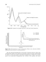
8.1 Multicast Address Allocation
....................................
8.2 Summary
...................................................
161
161
172
9. DHCP Failover: Using Clusters
....................................
9.1 Windows Clustering
...........................................
9.2 Building a Windows 2000 Cluster
.................................
9.3 Summary
...................................................
173
173
179
194
10. Integrating DHCP and DNS
.....................................
10.1 Domain Name System
........................................
10.2 Windows 2000 DNS Server
.....................................
10.3 Dynamic Update
.............................................
10.4 Summary
..................................................
195
195
195
202
212
11. Monitoring and Troubleshooting DHCP
............................
11.1 Monitoring DHCP
...........................................
11.2 Troubleshooting DHCP
........................................
11.3 Summary
..................................................
213
213
218
225
12. What Lies Ahead: IPv6 and DHCPv6
..............................
12.1 IPv6
......................................................
12.2 DHCP for IPv6
..............................................
12.3 Summary
..................................................
226
226
230
238
A. Appendix:DHCP Options
........................................
239
Colophon
......................................................
244
DHCP for Windows 2000
page 1
Preface
Dynamic Host Configuration Protocol (DHCP) provides a means of allocating and managing
IP addresses dynamically over a network. Before the advent of DHCP, administrators
configured each host on a network with an IP address, subnet mask, and default gateway.
Maintaining the changes and the logs of the changes took a tremendous amount of time and
was prone to error. DHCP uses a client/server model in which the network information is
maintained and updated dynamically by the system.
This book discusses DHCP in a Windows 2000 environment. It provides an introduction to
the DHCP protocol and shows how to implement a DHCP server into the network. It also
covers the more advanced features of DHCP.
The book begins with an overview of the TCP/IP protocol suite and shows how DHCP
coexists with the rest of the TCP/IP suite. It identifies DHCP's predecessors, RARP and
BOOTP, and explores the reasons that DHCP was developed. DHCP design considerations
are discussed, as well as the different methods of deployment. The book shows how to install
and configure DHCP servers in routed and non-routed environments and how to configure a
client to use DHCP. It also discusses how to administer a DHCP server in Windows 2000
using DHCP scopes, options, and leases. Finally, the book covers DHCP's close relationship
with Dynamic DNS, as well as some of the future directions for DHCP.
Conventions Used in This Book
The following conventions are used throughout this book:
Italic
Used for URLs, filenames, email addresses, and new terms when first defined.
Constant width
Used in examples to show the contents of files or the output from commands.
Constant bold
Used in examples to show commands or other text to be typed by the user.
Constant italic
Used in examples and command syntax definitions to show variables for which a
context-specific substitution should be made.
Indicates a tip, suggestion, or general note.
Indicates a warning.
DHCP for Windows 2000
page 2
How to Contact Us
We have tested and verified the information in this book to the best of our ability, but you
may find that features have changed (or even that we have made mistakes!). Please let us
know about any errors you find, as well as your suggestions for future editions, by writing to:
O'Reilly & Associates, Inc. 101 Morris Street Sebastopol, CA 95472 (800) 998-9938 (in the
U.S. or Canada) (707) 829-0515 (international/local) (707) 829-0104 (fax)
We have a web site for the book, where we list errata, examples, or any additional
information. You can access this page at:
To ask technical questions or comment on the book, send email to:
For more information about our books, conferences, software, Resource Centers, and the
O'Reilly Network, see our web site at:
Acknowledgments
Acknowledgments, acknowledgments, acknowledgments! They are oh so difficult. What if I
forget someone?! Well, let me try my best. If I left anyone out, please take me to lunch so I
can personally thank you . . . your treat of course . . .
This book began to take shape during a phone call with Robert Denn at O'Reilly. We
discussed the curious situation where there were many books for many subjects, but very few
for the oft-used, but little discussed, DHCP. Thus, this book was born. I would also like to
thank Neil Salkind, my agent, and everyone at Studio B for all of their help.
At O'Reilly, I would like to thank Sue Miller, my editor. Sue was instrumental in keeping this
project moving forward and sharpening my work. I especially need to thank Leanne Soylemez
for her thoroughness as the production editor and Rob Romano for redrawing my crappy . . .
err . . . displeasing figures.
And of course, the tech reviewers honed the details and, in the end, created a better book. I
must thank Andre Paree-Huff, Rory Winston, and Jim Boyce.
I must say I was very fortunate to work with the finest IT team around: System Support at
AstraZeneca Chesterbrook. Many thanks and memories go to Bill "The Fridge" Friedgen,
Chuck "Chooch" Boohar, Frank "No, not Kathy Lee's hubby, the decent one" Gifford, Mark
"When I was a . . . " Clayton, Richard "This is Richard!" Muir, Mike "Polly" Kliwinski, Matt
"Good eats" McWilliams, Tina Hughes, Tina Mohler, Adara Santillo (J), Paul "Hoagie Man"
Kern, Sandy "Could you please come to the data center" Garlinski, Ed "Salt Shaker"
Cartright, Steve Urick, The Honorable Marvin Mayes, George "The Agent" Oschenreither,
DHCP for Windows 2000
page 3
Chris Pignone, Ed Murawski, David Short, Rich Donato, and finally, the Men in Black: Brian
"Morphius" Seltzer and Jeff "The Angry Man" Sisson. Tell the Culinary Engineer at the
Deltaga I said hello and the coffee is weak.
Nor shall I ever forget the Ghosts of System Support's Past (kill the lights and queue the sad
music):
Jeff Tincher and Mark Marshall, both currently haunting Brandycare.
Jim Lange, rattling chains at Merck.
Bill Juliana, the only spirit wearing boat shoes and changing CDs at Comverse.
Lise Leonard, casually floating through the halls of Yoh.
And most of all I must thank my wife, Ginny, and my daughters, Lauren and Lindsey. Thank
you for always making me laugh and letting me know that play must always be more
important than work. The breaks that I took with you made it possible to recharge my
batteries and forge ahead with this project. I am forever grateful for your love and support.
—Neall Alcott
DHCP for Windows 2000
page 4
Chapter 1. TCP/IP Overview
Dynamic Host Configuration Protocol (DHCP) is an Internet standard protocol designed to
dynamically allocate and distribute IP addresses as well as additional TCP/IP configuration
information. DHCP is defined by RFCs 2131 and 2132. Working with the Internet
Engineering Task Force (IETF) and a number of other vendors, Microsoft was instrumental in
the development and standardization of DHCP.
Before the advent of DHCP, most TCP/IP configurations were maintained statically. An
administrator configured each individual host with a valid IP address, subnet mask, and
default gateway, as well as other TCP/IP configuration parameters. As you can guess,
configuring and administrating static TCP/IP configurations for multiple workstations and
network devices can be a burdensome task, especially if the network is large and/or changes
frequently. The exception to the rule was the use of two predecessors to DHCP, the RARP
and BOOTP protocols. These protocols are covered in more detail in Chapter 2.
DHCP uses a client/server model of operation (see Figure 1.1), where a DHCP client makes a
request to a DHCP server for an IP address and other configuration parameters. When the
DHCP client makes the request, the DHCP server assigns it an IP address and updates its
database, noting which client has the address and the amount of time that the address can be
used. This amount of time is known as a lease. When the time expires, the DHCP client needs
to renew the lease or negotiate a new lease for a different IP address. Through the use of
leases, the DHCP server can reclaim unused IP addresses.
Figure 1.1. The DHCP client/server model
Using DHCP allows an administrator to make changes to a client's IP configuration without
the need to visit each and every client. The user at the workstation only needs to release and
renew their DHCP lease. That is the power and benefit of DHCP.
The purpose of this chapter is to provide an overview of the data that DHCP is expected to
deliver: TCP/IP configuration information. The TCP/IP protocol suite is the common
language of the Internet and by far the dominant networking protocol suite in use today. One
must understand the many different facets of the TCP/IP protocol suite in order to configure,
maintain, and troubleshoot a Windows 2000 DHCP server.
DHCP for Windows 2000
page 5
This chapter begins with an overview of the TCP/IP protocol suite, describing the different
functions at the different layers of the Open Systems Interconnection (OSI) Model. It then
covers Media Access Control (MAC) addresses—what they are and how they operate,
followed by a very important area that one must understand: IP addressing and subnetting.
The next two sections finish up the chapter by giving an overview of the two types of name
resolution used in Microsoft Networking: DNS and WINS.
1.1 The TCP/IP Protocol Suite
In the 1960s, the Department of Defense's Defense Advanced Research Projects Agency
(DARPA) was in charge of developing a means of communication that would still function in
the event of a nuclear war. Development focused on the new theory of the packet-switched
network. All forms of networking up to this time (i.e., the phone system) had used a circuit-
switched network.
A circuit-switched network connects the sending and receiving stations by a single, direct
physical path. Circuit-switched connections are not shared with other traffic; they are meant
to be one-to-one. The telephone system is an example of a circuit-switched network. When a
person dials a phone number, the phone company equipment establishes a direct connection
between the caller's phone and the receiving phone. This connection lasts for the duration of
the call.
A packet-switched network operates by breaking the data to be transmitted into smaller
datagrams or packets. Each of these packets is numbered and sent out across the network.
Because the packets are individually numbered, they can take multiple paths to their
destination. There they will be put back in order and reassembled into the original data.
Figure 1.2 illustrates the concepts of these two types of networks.
Figure 1.2. Circuit-switched and packet-switched networks
The weakness with a circuit-switched network is that communication links have to be set up
ahead of time. If a circuit goes down, communication stops. The beauty of a packet-switched
network is that if a point of communication goes down, the data is automatically rerouted
through another location dynamically. In the end, it had great battlefield potential—which is
what DARPA was looking for. If a command center was taken out, communications could
DHCP for Windows 2000
page 6
continue by rerouting the data across any available medium: packet radio, satellite links, land
links, etc.
The TCP/IP protocol suite was developed and refined as part of the packet-switched network
project.
1.1.1 The OSI and DOD Reference Models
The TCP/IP protocol suite can be used to communicate over any type of networking medium.
This includes Local Area Network (LAN) and Wide Area Network (WAN) environments.
TCP/IP accomplishes this by using a modular design. The blueprint of this modular design
comes from the Department of Defense (DOD) Reference Model. The International Standard
Organization (ISO) also developed a seven-layer reference model called the Open Systems
Interconnection (OSI) Model. These models provide networking hardware and software
vendors with guidelines to create products that will be compatible in form and function across
multiple hardware and operating system platforms.
The DOD Reference Model consists of only four layers that are closely aligned with the OSI
Reference Model (see Figure 1.3):
Application Layer
This layer provides application interfaces, session establishment, data formatting, and
data conversion for applications running on a host system. This layer coincides with
the upper three layers of the OSI Model: Application Layer, Presentation Layer, and
Session Layer.
Transport Layer
This layer defines the method of communication between two systems: connection-
oriented or connectionless. This layer maps directly to the Transport Layer in the OSI
Model.
Internet Layer
The Internet Layer defines internetworking communications (i.e., routing). This layer
maps directly to the Network Layer of the OSI Model.
Network Interface Layer
This layer defines data-link and media access methods (i.e., Ethernet, Token Ring,
FDDI). This layer includes the remaining two layers of the OSI Model: Data Link and
Physical Layers.
DHCP for Windows 2000
page 7
Figure 1.3. Comparing the OSI and DOD Models
1.1.1.1 The Application Layer
The Application Layer defines protocols that provide email, file transfer, remote logins, and
drive-mapping capabilities to user applications. Some examples of protocols from the TCP/IP
Protocol Suite that reside at this layer are Telnet, FTP (File Transfer Protocol), SNMP
(Simple Network Management Protocol), SMTP (Simple Mail Transport Protocol), and DNS
(Domain Naming System).
1.1.1.2 The Transport Layer
The Transport Layer defines two protocols: Transmission Control Protocol (TCP) and User
Datagram Protocol (UDP). These protocols provide two separate functions:
Transmission Control Protocol (TCP)
TCP is a connection-oriented protocol. This means that TCP will provide a reliable
connection between two systems. TCP accomplishes this by sending
acknowledgments periodically to determine that datagrams are being received. If the
datagrams were not received, TCP resends them, thus insuring reliable delivery. TCP
is also responsible for breaking the data down into individual segments, numbering
them, and reassembling them at the destination.
User Datagram Protocol (UDP)
UDP is a connectionless protocol. Unlike TCP, UDP does not use any
acknowledgments, sending data blindly out onto the network to the destination. UDP
assumes that another layer, usually provided by timers and timeout periods, will
handle error correction. Implementations such as these are integrated into applications
by the developer. Since UDP does not have the overhead of TCP, it is considered
quick and efficient.
1.1.1.3 The Internet Layer
The Internet Layer is responsible for the delivery of packets across an internetwork. There are
two protocols that operate at this layer, Internet Protocol (IP) and Internet Control Message
Protocol (ICMP).
IP is the engine of TCP/IP, in charge of routing packets to and from logical addresses (i.e., IP
addresses). These logical addresses correspond to particular systems located on the network.
DHCP for Windows 2000
page 8
IP addresses are organized in a hierarchical manner, allowing networks to be subdivided into
subnets.
When a system wants to transmit data to a destination on a local network, IP takes the data
segment provided by TCP. It then adds a header to the segment that includes the destination
IP address and determines the destination's local subnet. IP sends the resulting packet to the
source's network interface, and thus to the local network. At the destination, IP receives the
packet, strips off the header information, and sends the resulting segment up to TCP. TCP
reassembles the data and sends it to the appropriate application (see Figure 1.4).
Figure 1.4. IP in a LAN environment
If the destination is not located on the same local network as the source, IP performs
additional steps to transmit the data.
IP first takes the data segment provided by TCP. It creates and attaches the header to the data
segment and determines whether the destination is on a local or remote subnet. In this case,
since the source and destination are not on the same local network, IP sends the packet to the
default gateway (i.e., the router on the local subnet).
At the router, IP receives the packet and, after analyzing the destination IP address,
determines that the packet is destined for another host on a remote subnet. IP determines the
subnet address for the destination and routes the packet to the network interface attached or
closer to the destination's local subnet.
Finally, the destination receives the packet, strips off the header, and sends the data segment
to TCP for reassembly (see Figure 1.5).
DHCP for Windows 2000
page 9
Figure 1.5. IP in a WAN environment
I will discuss IP addresses and subnetting in more detail later in this chapter.
ICMP provides message packets that report errors and other information, such as network
congestion, that may be affecting IP packets. There are some situations when this may occur:
1. The destination may be unreachable because there is no route.
2. The host may be unreachable because of a configuration issue or because a gateway
does not have the buffering capacity to forward the packet.
3. ICMP can also notify the source host that a more efficient route exists.
ICMP also provides an echo-request message. These messages are created by the
ping
command and are used to test connectivity between hosts on an internetwork. The
tracert
command also uses this mechanism to determine the router list and report the time between
routers (known as hop time).
Finally, if an IP packet's Time to Live (TTL) field has reached zero, a router discards the
packet. The router then generates an ICMP time-exceeded message to notify the source host
that the packet was discarded.
1.1.1.4 Network Interface Layer
The Network Interface Layer provides data link and media access capabilities to the upper-
level layers via hardware addresses. This layer allows TCP/IP to function across multiple
media-access protocols, such as Ethernet, Token Ring, FDDI, Frame Relay, ISDN, and xDSL.
Ethernet
Invented by Xerox, Ethernet is a baseband LAN specification that uses Carrier Sense
Media Access/Collision Detection (CSMA/CD). Ethernet can operate at 10 Mbps over
various cable types. There are also newer and faster implementations of Ethernet
available.
DHCP for Windows 2000
page 10
Token Ring
Invented by IBM, Token Ring is a token-passing LAN specification. Computers in a
Token Ring environment are connected to the network media in a closed ring.
Whichever computer possesses the Token is permitted to transmit data on the ring.
When the computer is finished transmitting, it passes the token on to the next
computer in the ring. If the next computer does not need to transmit, it, too, passes the
token on. By employing a token-passing scheme, collisions are avoided, since only
one computer is permitted to transmit. Token Ring can operate at 4 or 16 Mbps.
Fiber Distributed Data Interface (FDDI)
FDDI is a 100 Mbps, token-passing LAN standard using fiber-optic cables. FDDI uses
a token-passing scheme similar to Token Ring. FDDI consists of two fiber-optic rings,
a primary ring and a backup ring in case the primary fails. FDDI using multimode
fiber can operate up to a distance of 2 km. FDDI using single mode fiber can operate
to a distance of 40 km.
Frame Relay
Frame Relay is a telecommunications service meant to be used as a WAN technology.
It is the medium by which multiple LANs can be linked together. Frame Relay
operates by placing data into a frame for transmission. A virtual circuit connection is
created between two end devices, over which the frame is sent. Frame Relay provides
no error correction, so the devices on either end of the connection must supply error
correction. A switched data link layer protocol, Frame Relay can handle multiple
virtual circuits.
Integrated Services Digital Network (ISDN)
A digital communication protocol, ISDN can carry voice and data through
conventional copper telephone networks. An ISDN line is comprised of two different
channels, B and D. B (or bearer) channels are the main conduits for data and voice
communications. D (or data) channels are used to transmit setup and control signals
for the entire ISDN connection. ISDN comes in two levels of service: Basic Rate
Interface (BRI) and Primary Rate Interface (PRI). BRI consists of two B channels (64
Kbps) and one D channel (16 Kbps). As a result, BRI ISDN operates at speeds up to
128 Kbps. PRI consists of 23 B channels and one 64 Kbps D channel. PRI ISDN
operates at up to 1.544 Mbps. An ISDN adapter must be installed on both ends of the
connection to handle the digital signal.
xDSL
A digital technology that uses the existing copper telephone infrastructure to transmit
voice and data. Typical telephone wire in the United States contains four wires. Only
two of the wires are used for telephone service; the other two remain unused. xDSL
utilizes all of the wires to carry a digital signal at a frequency higher than that of voice
communications. As a result, a telephone line utilizing xDSL can carry voice and data
communications simultaneously. xDSL is a faster alternative to ISDN and operates at
a number of speeds such as 640 Kbps, 1.6 Mbps and up. Currently xDSL suffers from
DHCP for Windows 2000
page 11
major distance limitations, usually less than 20,000 feet from the central telephone
office.
I briefly describe Ethernet here because it is by far the most popular LAN technology. It is
cheap, easy to use and understand, and flexible.
Ethernet uses a media access process known as CSMA/CD (Carrier Sense Media
Access/Collision Detect). This works by allowing any host on the network to transmit at any
time, but before transmitting, the host must listen for traffic on the network. If no traffic is
detected, the host can proceed. If two hosts on the network transmit at the same time, a
collision occurs. When a collision occurs, the offending stations are each set to wait a random
length of time before retrying the transmission.
Ethernet comes in primarily three flavors: IEEE 802.3 (10 Mbps), Fast Ethernet (100 Mbps),
and Gigabit Ethernet (1000 Mbps).
IEEE 802.3
The standardized version of Ethernet. It operates at a data rate of 10 Mbps.
Fast Ethernet
A form of Ethernet that provides a data rate of 100 Mbps. Workstations that are
equipped with IEEE 802.3 network adapters can connect to a Fast Ethernet-based
network, however they are still limited to 10Mbps data transmission.
Gigabit Ethernet
Another form of Ethernet that provides a data rate of 1 Gbps, or 1 gigabit. Gigabit
achieves its tremendous speed by using fiber-optic cable as the network medium.
Copper cabling can also be used, but it severely limits the distance Gigabit Ethernet
can operate at. Workstations equipped with IEEE 802.3 and Fast Ethernet network
adapters can attach to Gigabit Ethernet, but they are still limited to their respective
data transmission rates.
This essentially concludes the discussion of the DOD Reference Model. The remaining
sections of this chapter deal with more specific TCP/IP concepts. This provides an
understanding of some of the configuration parameters that a DHCP server provides to DHCP
clients.
1.2 MAC Addresses
Media Access Control (MAC) addresses are hardware addresses that uniquely identify a
network interface card (NIC) in a host.
MAC addresses are 48 bits in length and are written as 12 hexadecimal digits. The first 6
hexadecimal digits identify the manufacturer of the NIC. This is known as the Organizational
Unique Identifier (OUI), which is administered by the IEEE. Each manufacturer of Ethernet
devices must register with the IEEE. The remaining 6 hexadecimal digits are used as a serial
number, which is administered by the individual manufacturer (see Figure 1.6).
DHCP for Windows 2000
page 12
Figure 1.6. Example of MAC addresses
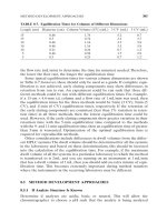
Table 1.1 lists the OUI numbers for several well-known NIC manufacturers.
Table 1.1. List of Common OUI Numbers
Manufacturer OUI Number
Novell 00-00-1B
Cisco 00-00-0C
3Com 00-20-AF
HP 08-00-09
Apple 08-00-07
IBM 08-00-5A
Intel 00-90-27
Microsoft 00-50-F2
1.2.1 ARP
In order for communication to take place across an internetwork, a MAC address must be
resolved to a logical network address (an IP address, which I will cover in more detail in the
next section). This is accomplished by using the Address Resolution Protocol (ARP). ARP
works slightly differently depending on whether it is used in a LAN or WAN environment.
In a LAN environment, ARP is used when a host needs to transmit data to another host (see
Figure 1.7). To find out the destination host's MAC address, the source broadcasts an ARP
request on the LAN. The ARP request includes the IP address to be resolved. Because it is a
broadcast, all hosts connected to the LAN receive and process this request. When the
destination host receives the broadcast, it responds directly with an ARP reply that contains its
MAC address. Also, any other host that receives the ARP request can respond if the requested
address is in their ARP cache. The source host will then add the destination's MAC address to
its ARP cache and begin transmitting data.
The ARP cache is dynamic and entries are removed after two minutes. If
an ARP entry was reused, the entry remains in the ARP cache for ten
minutes.
DHCP for Windows 2000
page 13
Figure 1.7. Example of ARP in a LAN environment
In a WAN environment, ARP operates mostly in the same manner, except that the source and
destination are not on the same LAN (see Figure 1.8). In this case, the source host compares
its IP address with the destination's IP address and determines that it is located on a different
subnet (through a process called ANDing, which I'll discuss later in this chapter). At this point
the source host broadcasts an ARP request to determine the MAC address of its default
gateway. The router replies with its MAC address, which is then added to the source's ARP
cache. Now, when the source wants to communicate with the destination host, it addresses its
data packets to the router's MAC address. The packet's destination IP address still contains the
destination's IP address. The router then forwards the information to the destination host on
the other subnet.
DHCP for Windows 2000
page 14
Figure 1.8. Example of ARP in a WAN environment
1.3 IP Addressing
IP addressing is the heart of the TCP/IP-based internetwork. The process of routing IP packets
is possible because of this logical addressing scheme.
An IP address is a logical 32-bit binary number that identifies a system on an internetwork.
An IP address comprises two parts—the network portion and the host portion. The network
portion of an IP address tells the host what logical network it is located on. The host portion
identifies that particular host.
1.3.1 IP Address Format
Because humans tend to have trouble remembering and evaluating binary numbers, IP
addresses are expressed in dotted decimal notation. A 32-bit binary IP address is written out
in four octets, each of which contains eight bits. Each bit position in an octet represents a
value (one of 128, 64, 32, 16, 8, 4, 2, 1); the sum of these values, when totaled, represents the
octet's decimal value (see Figure 1.9).
DHCP for Windows 2000
page 15
Figure 1.9. Dotted decimal example
1.3.2 IP Address Classes
Initially, when IP was developed, the IP address space was divided into distinct IP address
classes to determine where the network portion stops and the host portion begins. The value
of the first octet and its highest order (leftmost) bits determine the class. There are five IP
address classes, three of which (A, B, and C) are available for commercial use (see Figure
1.10). Class D is reserved for IP multicasting. Multicasting allows multiple computers in the
same multicast group to receive the same data transmission, sort of like a directed broadcast.
Class E is strictly reserved for research use by the Internet Engineering Task Force (IETF).
Figure 1.10. IP address classes
1.3.2.1 Class A
In a Class A IP address, the network portion is represented by the first octet; it has in its
leftmost bit. In other words, if you were to set all the remaining bits in the first octet to 0s, the
resulting value for the octet would be 0. If you set all the remaining bits in the first octet to 1s,
the resulting value would be 127. Therefore all Class A IP addresses fall into the 0-127 range
for the first octet. This also results in 127 possible networks and a maximum of 16,777,214
hosts on each network. (Please note that the network 127.0.0.0 is reserved for loopback
addresses.) Figure 1.11 summarizes the characteristics of the Class A address class.
DHCP for Windows 2000
page 16
Figure 1.11. Class A
1.3.2.2 Class B
In a Class B IP address, the first and second octets represent the network portion; it has 10 in
its two leftmost bits. A Class B IP address falls into the 128 to 191 range for the first octet.
This results in 16,384 possible networks and a maximum of 65,534 hosts on each network.
Figure 1.12 summarizes the characteristics of the Class B address class.
Figure 1.12. Class B
1.3.2.3 Class C
In a Class C IP address, the network portion is represented by the first, second, and third
octets; it has 110 in its three leftmost bits. A Class C IP address falls into the 192 to 223 range
for the first octet. This results in 2,097,152 possible networks and a maximum of 255 hosts on
each network. Figure 1.13 summarizes the characteristics of the Class C address class.
Figure 1.13. Class C
Please note that some host and network addresses cannot be used. These are discussed later in
this chapter.
1.3.3 IP Subnetting
IP address classes are not always the most efficient way to design an IP addressing scheme.
There aren't many companies that need a Class A address with 16 million hosts, and there
may be smaller companies that need more addresses than a Class C network can provide. As
you can see, this method could lead to a tremendous number of wasted IP addresses.
DHCP for Windows 2000
page 17
The Internet Engineering Task Force (IETF) saw this and submitted RFC 950 to facilitate the
addition of a third level to the existing two-level hierarchy created with IP address classes.
This third level is known as subnetting. Subnets are created by taking leftmost bits from the
host portion of an IP address and applying them to the network portion (see Figure 1.14).
Figure 1.14. Subnetting a Class C address
Subnetting gives network designers and administrators the ability to divide larger networks
into smaller, more efficient networks. Since subnets are under local administration, the
outside world (via routing tables) does not need to know of their existence.
Subnetting is made possible by the use of a subnet mask. A subnet mask, along with the IP
address classes, determines where the network and subnet portions of an IP address end and
the host portion begins. A subnet mask is a 32-bit binary number. Starting at the leftmost bit,
1s are placed in every bit that is part of the network and subnet portions. The remaining bits
contain 0s (see Figure 1.15).
Figure 1.15. Subnet mask example
So how does IP determine the subnet where a host is located? There is a set process that a
router or host performs to determine the subnet address. This process is commonly known as
Logical ANDing. Logical ANDing is simply a Boolean operation that follows three basic
rules: 1 "ANDed" with 1 is 1; 1 "ANDed" with is 0; "ANDed" with is 0. In other words, if 1 =
True and = False:
1 "ANDed" with 1 is 1 True AND True = True
1 "ANDed" with 0 is 0 True AND False = False
0 "ANDed" with 0 is 0 False AND False = False
The process begins with the IP destination address and the internal subnet mask. A Logical
AND operation is performed which causes the host portion of the destination IP address to be
removed—resulting in the subnet address. Here's an example where the ANDing operation is
performed on a Class C subnet. Take a moment and observe the last octet in the IP address:
DHCP for Windows 2000
page 18
Destination IP Address:
192.168.0.214 11010110
Subnet Mask:
255.255.255.224 11100000
Resulting Subnet Address:
192.168.0.192 11000000
Given the preceding example, we have determined that the IP address 192.168.0.214 with a
subnet mask of 255.255.255.224 is located on the subnet 192.168.0.192.
Taking the example further, what is the maximum number of hosts on this segment and what
are the starting and ending IP addresses?
Before we answer these questions, I want to introduce you to a little formula that makes life in
the IP world easier. This formula is 2
n
-2. Using this formula, one can determine the number
of hosts in a subnet. 2
n
represents the number of hosts that can be created, where 2 is the
number of possible values for each bit (0 or 1—remember we're dealing in binary here!) and n
is the number of bits taken from the host portion of the network address. I subtract two from
2n because addresses of all 1s and all 0s cannot be used.
Now let's take a moment to answer the first question: what is the maximum number of hosts
on this subnet, 192.168.0.192? This can be determined by examining the portion of the subnet
mask that is not masked, or contains 0's. For the subnet mask of 255.255.255.224, the host
portion contains 5 zeros. This means that the n
exponent in our trusty little formula would
have a value of 5. The number of hosts is then 2
5
-2. Which results in...get out those
calculators...30. So, on subnet 192.168.0.192, the maximum number of hosts is 30. That
wasn't so bad, was it?
OK, we answered the first question. Now let's figure out the second question: what are the
starting and ending IP addresses on subnet 192.168.0.192? Or another way to ask this
question is, what is the range of IP addresses on subnet 192.168.0.192?
To answer this we need to again examine the subnet mask 255.255.255.224.
First, note that we are only concerned with the last octet, 224, since this octet contains the
host addresses. Take 224 and convert it into binary. This results in 11100000. To figure out
the address ranges possible with this subnet mask, we need to determine the value of the
furthest bit to the right that is set to 1. For this subnet mask, there are three 1s, and the last set
bit is 32.
This value, 32, is known as the subnet offset value. The subnet offset value tells you that
every 32 addresses results in another subnet. We can now determine the subnet's address
range by taking the subnet address, 192.168.0.192, and adding 32, which results in
192.168.0.224. 192.168.0.224 is the start of the next subnet after 192.168.0.192.
Since 192.168.0.224 is the start of the next subnet, let's subtract 1 from this address, which
results in 192.168.0.223. This is the last host address in the 192.168.0.192 subnet.
Determining the first host address is simple: add 1 to the subnet address, 192.168.0.192,
which results in 192.168.0.193.
So, to answer the second question, 192.168.0.193 is the first host address, and 192.168.0.223
is the last host address in the 192.168.0.192 subnet.
DHCP for Windows 2000
page 19
Note that if we set another bit to 1 in the subnet mask, or, in other words, move the masked
bits further to the right, the subnet offset value gets smaller. This results in a smaller address
range, or fewer hosts per subnet. If we move the masked bits to the left, the subnet offset
value grows larger, resulting in larger address ranges.
Now let's expand our discussion to the enterprise level. Here we will walk through a situation
where subnetting would be used in a large internetwork environment. An organization has
been assigned the Class C network address 201.222.5.0. This company has 20 remote offices,
each containing 5 workstations and a server.
First, determine the subnet field size that will yield enough subnets in this situation.
Remember the 2
n
-2 formula? Using that formula again, one can determine the number of
subnets created.
In our example, the network address is 201.222.5.0. We know that it is a Class C address
because the first octet falls into the Class C range: 192 to 223. Given that it is a Class C
address, the network portion is made up of the first three octets. This represents 24 bits from
the 32 bits in the address. This leaves the remaining octet, or 8 bits, for the host portion. Now
let's determine the number of bits required. Using the formula 2
n
-2, simply plug in the
number of bits. 2
5
-2 = 30 possible subnets, which provides the required 20 subnets, with 10
left over for future growth.
Why use 5 bits? Why not use 4? 2
4
-2 = 14 subnets, which is not enough. Using 6 bits, 2
6
-2 =
62 subnets, which works for the subnets but does not leave enough host addresses.
Recall that the bit furthest to the right is the subnet offset value. This value determines the
subnet addresses.
We used 5 bits for the subnet portion. The fifth bit value from the right is 8. Therefore the
subnet addresses are all multiples of 8: the first subnet is 201.222.5.8, the next is
201.222.5.16, etc.
The host address range begins with the subnet address plus 1. The range ends with the next
subnet address minus 2.
Our first subnet is 201.222.5.8. The host range for this subnet would be 201.222.5.17 through
201.222.5.22.
To conclude, IP subnetting happens to be one of those subjects that many people do not
immediately comprehend. It needs to be studied and put to practical use. Once this happens,
people understand it, and they never forget it. Give subnetting time and work with it. It will
"click."
1.3.4 Classless Interdomain Routing (CIDR)
As the Internet unexpectedly grew in popularity, it became apparent that something must be
done about the depletion of registered Internet networks and the growth of Internet routing
tables. In particular, Class B networks were nearly completely allocated by the late 1980s.
The reason for the depletion of this particular class was the lack of a class whose size was
appropriate for a mid-size organization. A mid-size organization would require more than the
DHCP for Windows 2000
page 20
maximum 254 hosts a Class C network provides, while the 65,534 hosts a Class B network
provides were too many. If an organization needed more than 254 hosts, it would be assigned
a Class B network, essentially wasting many IP addresses.
Classless Interdomain Routing (CIDR), defined in RFC1519, was implemented to slow the
growth of the Internet routing tables and the need to allocate more network numbers.
CIDR slows routing table growth by aggregating multiple networks to form a single network.
This is known as supernetting. Supernetting also alleviates the Class B address depletion
problem by allowing multiple Class C networks to be aggregated. These aggregrated Class C
networks provide a number of hosts somewhere between a Class C and a Class B network.
For example, a company requires 6500 host addresses. To achieve this without allocating a
Class B address, the company is issued the network address 192.168.0.0/19. The /19
represents the number of bits in the network number, much like a subnet mask. This network
actually represents 32 Class C addresses, 192.168.0.0 to 192.168.31.0. The IP address
utilization level of the 192.168.0.0/19 network is almost 80%, whereas the utilization level of
a Class B network would have been about 10%. Also, only one route is added to the routing
table. When a router outside the company needs to send data to a host on subnet 192.168.16.0,
it uses the 192.168.0.0/19 routing table entry. The company's router then forwards the data to
the correct subnet.
CIDR solves the two problems of growing router tables and the need for more network
addresses quite nicely; however, there is an issue that needs to be considered. If you are
working entirely with modern routing technology, such as the routing protocol Open Shortest
Path First (OSPF), using CIDR is possible and not entirely difficult. However, if you are
using older technology such as Routing Information Protocol v.1 (RIP1), CIDR cannot be
used. RIP1 uses IP address classes to determine routes to a network. It does not use subnet
masks to determine the network address. It simply observes the address' first octet to
determine which class the IP address belongs to. So keep this in mind if you want to use
CIDR.
1.3.5 IP Address Restrictions
Certain IP addresses have special meanings and therefore cannot be used. Table 1.2 lists these
addresses and describes why they cannot be used. Please note that some newer networking
equipment allows some use of these restricted addresses. Refer to your equipment's operating
manual for more information.
Table 1.2. Special IP Addresses and Their Uses
Special Address Description
0.0.0.0
This host on this network. Can be used by the BootP process for a host that does not know
its IP address but does have a hardware address.
255.255.255.255 This is used for a broadcast to all hosts on the same physical medium.
Host Address of All
1s
This is used for a broadcast to all hosts on the specified network or subnet.
Network Address of
127
This is used as an internal loopback address. Packets addressed like this are used only for
testing the local TCP/IP stack.
DHCP for Windows 2000
page 21
1.4 DNS and Hostnames
Trying to remember many IP addresses is nearly impossible for anyone, especially with the
growth of the Internet during the past 10 years. Hostnames make everyone's life easier by
giving an IP address a memorable name. After all, remembering microsoft.com is much easier
than remembering 207.46.130.149.
Originally, in the dark days of the Internet and TCP/IP, hostname resolution was left to a
single text file, called the HOSTS file. Hostnames were manually added to this file, and then
the file was downloaded and distributed to each TCP/IP host. HOSTS files work fine and are
manageable if your network is small. HOSTS files in Windows NT and Windows 2000 are
stored in the %systemroot%\SYSTEM32\DRIVERS\ETC directory. Example 1.1 shows a
sample HOSTS file.
Example 1.1. Sample HOSTS File
# Copyright (c) 1994 Microsoft Corp.
#
# This is a sample HOSTS file used by Microsoft TCP/IP for Chicago
#
# This file contains the mappings of IP addresses to host names. Each
# entry should be kept on an individual line. The IP address should
# be placed in the first column followed by the corresponding host name.
# The IP address and the host name should be separated by at least one
# space.
#
# Additionally, comments (such as these) may be inserted on individual
# lines or following the machine name denoted by a '#' symbol.
#
# For example:
#
# 102.54.94.97 rhino.acme.com # source server
# 38.25.63.10 x.acme.com # x client host
127.0.0.1 localhost
192.168.0.l cg141484-a
192.168.0.254 proxy
192.168.0.2 nalcott
The HOSTS file method of hostname resolution became more cumbersome and inefficient as
the Internet grew. In 1984, two new RFCs (882 and 883) were released detailing DNS. These
RFCs have since been superceded by RFCs 1034 and 1035.
DNS is a distributed database that allows local administrators to maintain their portion of the
DNS database while allowing access to it for hostname resolution across the entire Internet.
DNS is implemented in a client/server arrangement. The server portion is driven by name
servers. Name servers hold the segment of the DNS database (called a zone) that they have
authority over. The client portion is known as a resolver. This can be any TCP/IP client that
supports DNS. Whenever you are using the Internet, whether it is the World Wide Web or
simply email, you are using DNS.
The structure of the DNS database can be described as an inverted tree (see Figure 1.16). The
top of the tree (or the trunk) is known as the root domain. It is shown as a single dot (".").