BUILDING BROADBAND NETWORKS phần 4 docx
Bạn đang xem bản rút gọn của tài liệu. Xem và tải ngay bản đầy đủ của tài liệu tại đây (10.82 MB, 61 trang )
rates at 40 Gbps — and ultimately at 1 Tbps — this DWDM infrastructure enables
seamless access to bandwidth-intensive multimedia applications. Capabilities of
optical network elements such as optical add-and-drop multiplexers (OADMs) in
provisioning transparent optical transmission functions and network management
services are also examined.
3.25 UNDERSEA OPTICAL NETWORK SOLUTIONS
Spiraling demand for high-capacity networks to support multimedia services and
applications contributes to deployment of undersea optical networks. Initially imple-
mented in the mid-1990s, undersea optical networks originally employed
SONET/SDH infrastructures. Present-day undersea initiatives typically employ
WDM and DWDM technologies for enabling oceanic transmissions at multigigabit
and multiterabit rates over long distances. Representative initiatives in the underwa-
ter optical network domain are now explored.
3.25.1 ALCATEL
3.25.1.1 SEA-ME-WE 3
Alcatel provisions network management operations for undersea network configu-
rations such as SEA-ME-WE 3. Featuring ATM-over-WDM and SDH-over-WDM
technologies, the SEA-ME-WE 3 configuration upon completion will extend over
38,000 kilometers and feature 40 landing points in 34 countries between the Euro-
pean Union and Asia. Transmission rates ranging from 2.488 Gbps to 50 Gbps over
two pairs of undersea fiber optic cabling will be enabled. Each optical fiber strand
supports eight wavelengths or fiber optic channels. Each wavelength or channel
supports multimedia transmission at 2.488 Gbps (OC-48 or STM-16). Network
segments between Hong Kong and Korea are currently in operation.
3.25.2 AT&T
AT&T employs WDM technology to provide communications services via a trans-
Atlantic fiber optic ring network to landing points in the United States, Great Britain,
and France. This undersea network also utilizes forward error correction (FEC) control
mechanisms for enabling reliable transmission of multimedia applications at 10 Gbps.
Infrastructure upgrades supporting transmission rates at 20 Gbps are in development.
3.25.3 FLAG (FIBER OPTIC LINK AROUND THE GLOBE) TELECOM
FLAG (Fiber Optic Link Around the Globe) Telecom operates underwater networks
that support SDH-over-DWDM technologies and administers network landing points
in Italy, Egypt, Spain, Jordan, the United Arab Emirates, Saudi Arabia, Malaysia,
India, Korea, Thailand, and China. FLAG Telecom gateways situated in Eastern
Africa, the Asia-Pacific region, the United Kingdom, South America, the Middle
East, Latin America, the European Union, and the United States are designed to
enable worldwide connectivity. FLAG Telecom also supports interconnections of
0889Ch03Frame Page 143 Wednesday, April 17, 2002 3:04 PM
© 2002 by CRC Press LLC
undersea networks to terrestrial broadband networks such as the FLAG Europe-Asia
fiber optic network and the GTS Trans-European DWDM Network.
FLAG Telecom buries optical fiber cable below the seabed to eliminate disrup-
tion to undersea habitats and to safeguard undersea networks from damage caused
by strong harbor currents, adverse weather conditions, electromagnetic interference,
and disruptions associated with congested shipping lanes. The FLAG Telecom under-
sea fiber optic system supports rates at 2.488 Gbps (OC-48 or STM-16) for enabling
high-speed multimedia transmission, fully protected voice services, and Internet broad-
casts. Upon completion, the FLAG undersea DWDM network will interlink landing
points in the United Kingdom and Japan via the Pacific Ocean, the South China Sea,
the Indian Ocean, the Red Sea, the Mediterranean Sea, and the Atlantic Ocean.
3.25.3.1 FA-1 (Flag Atlantic-1) Trans-Atlantic Network
As with other FLAG undersea initiatives, the FA-1 (Flag Atlantic-1) Trans-Atlantic
Network employs laser-generated lightwaves for transmitting digital information via
WDM and DWDM technologies. The FA-1 Trans-Atlantic Network features a dual
terrestrial and undersea optical fiber infrastructure for interconnecting landing points
in the United States, the European Union, the Asia-Pacific region, and the Middle
East. In addition, the FA-1 Trans-Atlantic Network provisions 5 Tbps of total raw
capacity and supports secure digital transmissions via an SDH-over-DWDM back-
bone network at rates reaching 2.5 Tbps.
3.25.3.2 FL-A1 (FLAG ASIA) Segment
Currently in development by FLAG Telecom, the FL-A1 (Flag Asia) segment is an
undersea DWDM network that provisions services for international communications
carriers. GTS expects to lease protected capacity on FL-A1 for enabling seamless
connections at 400 Gbps and unprotected capacity at 800 Gbps in an area that extends
from landing points in New York to the GTS Trans-European DWDM Network.
3.25.4 FRANCE TELECOM
France Telecom employs an SDH-over-WDM optical infrastructure for fiber optic
undersea networks that support high-speed, full-duplex voice, video, and data trans-
mission, and provision on-demand bandwidth. France Telecom participates in the
Americas II and Atlantis-2 undersea fiber optic initiatives.
3.25.4.1 Americas II Undersea Network
The Americas II fiber optic undersea network links North America, South America, and
the Caribbean region in a WDM configuration that extends over 8,000 kilometers. This
system features four pairs of fiber optic cabling and a landing point in Martinique.
Information transport at 40 Gbps is supported.
3.25.4.2 Atlantis-2 Undersea Network
The Atlantis-2 WDM undersea fiber optic network fosters interconnections between
landing points in Portugal, the Canary Islands, the Cape Verde Islands, Senegal,
0889Ch03Frame Page 144 Wednesday, April 17, 2002 3:04 PM
© 2002 by CRC Press LLC
Brazil, and Argentina. This configuration employs two pairs of fiber optic cabling.
Each fiber optic strand supports rates ranging between 5 Gbps and 20 Gbps. The
network extends to 12,000 kilometers.
3.25.5 GLOBAL CROSSING
3.25.5.1 Atlantic Crossing 1 (AC-1) and Atlantic Crossing 2 (AC-2)
Undersea Networks
Sponsored by Global Crossing, the Atlantic Crossing 1 (AC-1) trans-Atlantic
DWDM undersea fiber optic network links landing points in Germany, the Nether-
lands, the United Kingdom, and New York City in a fiber optic configuration
extending to 14,000 kilometers. In a related initiative, Global Crossing also supports
a 2.5 Tbps DWDM undersea network configuration called Atlantic Crossing 2 (AC-
2). The AC-2 undersea network interoperates with the AC-1 installation.
3.25.5.2 Mid-Atlantic Crossing and Pan American Crossing
Undersea Networks
Developed by Global Crossing, the Mid-Atlantic Crossing undersea fiber optic
network interconnects landing points in the Caribbean region and the Eastern United
States in a WDM configuration that extends to 7,500 kilometers. Also a Global
Crossing project, the Pan American Crossing undersea WDM fiber optic network
interconnects landing points in the Caribbean region, Central America, Mexico, and
the Western United States in a configuration covering 8,900 kilometers.
3.25.5.3 Global Crossing Undersea Fiber Optic Network in Japan
In Japan, Global Crossing supports implementation of a high-speed undersea fiber
optic network equipped with DWDM technology that interlinks landing points in
Tokyo, Nagoya, and Osaka in a configuration that extends to 1,200 kilometers.
3.25.6 IAXIS
Iaxis supports construction of a 10,000-kilometer WDM network in the Mediterra-
nean Sea that interlinks landing points in Africa, the European Union, and the Asia-
Pacific region.
3.25.7 SOUTH ATLANTIC TELEPHONE/WESTERN CABLE/SOUTHERN AFRICA
F
AR EAST, PHASE 3 (SAT-3/WASC/SAFE)
Currently in development, SAT-3/WASC/SAFE is an undersea fiber optic network
that accommodates Africa’s expanding telecommunications requirements. SAT-
3/WASC segments support connections between landing points at sites in Senegal,
Portugal, the Ivory Coast, Ghana, Nigeria, and Angola. A WDM Optical Layer
enables transmission rates at 20 Gbps, with upgrades to 40 Gbps available. SAFE
segments interlink landing points in South Africa, Mauritius, and Malaysia.
0889Ch03Frame Page 145 Wednesday, April 17, 2002 3:04 PM
© 2002 by CRC Press LLC
As with other undersea networks, SAT-3/WASC/SAFE implementation involves
mapping the topography of the ocean bed with sonar prior to fiber optic installation.
Aluminum sheaths protect optical fiber from shark bites. These sheaths are situated
between depths of 1,000 meters and 3,000 meters. Moreover, fiber optic cabling at
shallower depths is also encased in aluminum sheaths to prevent damage from rocks,
fishing nets, and anchors. A satellite remote control and surveillance system for SAT-
3/WASC/SAFE aids in the identification of network faults. Upon completion, this
network will support transmission over a maximum of eight fiber optic pairs for
enabling a total rate of 80 Gbps.
3.25.8 TELECOM NEW ZEALAND, OPTUS, SOUTHERN CROSS CABLES, AND
W
ORLDCOM
3.25.8.1 Trans-Pacific Southern Cross Network
Telecom New Zealand, Optus, Southern Cross Cables, and WorldCom sponsor the
Trans-Pacific Southern Cross Network. Presently in development, this self-restoring,
undersea fiber optic, long-haul configuration interlinks landing points in Australia,
New Zealand, Fiji, Hawaii, and the West Coast of the United States in a terrestrial
and undersea fiber optic network configuration. A high-speed, high-capacity config-
uration, the Trans-Pacific Southern Cross Network employs SONET/SDH-over-
WDM/DWDM technologies for provisioning an initial capacity of 40 Gbps on each
fiber optic pair. Upon completion, the Trans-Pacific Southern Cross Network will
enable transmission rates reaching 480 Gbps and transport high-quality, high-per-
formance voice, video, and data signals in an area of coverage that extends to 30,500
kilometers.
3.26 SUMMARY
The spiraling increase in the volume of information traffic transmitted across com-
munications networks contributes to the development of terrestrial and undersea
optical fiber network solutions for provisioning additional network capacity. The
communications capacity of fiber optic cabling is immense. According to the NSF
(National Science Foundation), a single strand of optical fiber possesses an accessible
bandwidth approaching 100,000 Gigahertz (GHz). By comparison, the entire radio
spectrum managed by the Federal Communications Commission (FCC) for enabling
FM and AM radio and television programming, cellular telephony, and satellite
services consists of approximately 60 GHz.
In this chapter, representative SONET/SDH solutions in enabling dependable
and reliable voice, video, data, and still-image transmission, and rapid access to
bandwidth-intensive applications are described. Capabilities of SONET/SDH imple-
mentations in fostering reliable tele-education and telemedicine programs, telecol-
laborative research, and E-government activities are examined.
Optical networks are evolving at a remarkable pace. Unprecedented demand for
high-speed, high-capacity optical solutions contributes to the popularity of optical
fiber networks that employ third-generation WDM and DWDM optical technologies
0889Ch03Frame Page 146 Wednesday, April 17, 2002 3:04 PM
© 2002 by CRC Press LLC
and the emergence of optical network configurations such as PONs, SuperPONs,
APONs, and AONs. Distinguishing characteristics of these optical network config-
urations are highlighted.
Distinctive attributes of WDM and DWDM technologies, architectures, compo-
nents, and solutions are introduced. The role of WDM and DWDM technologies in
contributing to the development of a new Optical Layer that serves as a Sublayer
of the Physical Layer or Layer 1 of the OSI (Open Systems Interconnection) Ref-
erence Model is highlighted. Network services provided by third-generation WDM
and DWDM technologies in supporting extendible, reliable, and dependable next-
generation network configurations and provisioning access to bandwidth-intensive
multimedia applications with differentiated QoS guarantees in the educational, cor-
porate, medical, and governmental sectors are reviewed. Representative examples
of terrestrial and undersea WDM and DWDM configurations in supporting ultrafast
information transport and providing unprecedented bandwidth for next-generation
Internet innovations and services are also examined.
3.27 SELECTED WEB SITES
Advanced Research and Development Network Operations Center
(ARDNOC). CA*net3 Optical Internet Backbone. Last modified on April
23, 2001.
Available: />Advanced Technology Demonstration Network. ATDNet. Last modified on
August 8, 2001.
Available: />Alcatel. Submarine Networks.
Available: />All-Optical Networking Consortium. Homepage. Last modified on July 30,
1997.
Available: />Canadian Network for the Advancement of Research, Industry, and Education
(CANARIE). CA*net3. Last modified on September 25, 2001.
Available: />European Commission. The ACTS Information Window.
Available: />FLAG (Fiber Optic Link Around the Globe) Telecom. Overview.
Available: http://www.flag.bm/index_e1.htm
France Telecom. Welcome to France Telecom’s Marine Activities Website.
Available: />Global Crossing. The Expanding Network.
Available: = Network
High-Speed Connectivity Consortium (HSCC). Home Page. Last modified on
July 12, 2001.
Available: />LightReading: The Global Site for Optical Networking.
Available: />0889Ch03Frame Page 147 Wednesday, April 17, 2002 3:04 PM
© 2002 by CRC Press LLC
Massachusetts Institute of Technology Lincoln Laboratory Advanced
Networks Group. BoSSNET (Boston-South Network).
Available: />Metropolitan Research and Education Network. MREN: Advanced networking
for advanced applications. Last modified on February 21, 2001.
Available: />Optical Domain Service Interconnect Coalition.
Available: />PennWell Corporation. LIGHTWAVE. Fiber Optic Communications,
Bandwidth Access, and Telecommunications.
Available: />Wisconsin Bureau of Network Services. BadgerNet Overview. Last modified
on August 20, 2001.
Available: />University Corporation for Advanced Internet Development (UCAID). About
Abilene.
Available: />U.S. Department of Defense Advanced Research Projects Agency (DARPA)
Information Technology Office (ITO). Next-Generation Internet (NGI).
Project List.
Available: />U.S. Department of Defense Advanced Research Projects Agency (DARPA)
Information Technology Office (ITO). Next-Generation Internet (NGI).
SuperNet Testbed.
Available: />0889Ch03Frame Page 148 Wednesday, April 17, 2002 3:04 PM
© 2002 by CRC Press LLC
4
Ethernet Networks
4.1 INTRODUCTION
The popularity of Web entertainment, E-commerce, and distance learning, and the
concurrent demand for ready access to Web applications in the local networking
environment, contribute to the widespread implementation of Ethernet communica-
tions networks. A flexible, reliable, scalable, and dependable technology, the Ethernet
technology suite sustains intranet, extranet, and Internet connectivity in LAN (Local
Area Network) environments and interoperates with wireline and wireless solutions.
The Ethernet technology suite is defined by a series of specifications and sup-
plements associated with the IEEE (Institute of Electrical and Electronics Engineers)
802.3 family of LAN standards. An Ethernet LAN supports operations in a delimited
geographic area such as a classroom, a multistory office building, a factory, or a
cluster of buildings on a university campus, and enables information exchange and
shared workgroup applications over a common communications medium. The mul-
tiservice Ethernet platform interworks with technologies that include Frame Relay
(FR), FDDI (Fiber Data Distributed Interface), Fibre Channel (FC), DSL (Digital
Subscriber Line), cable modem, WDM (Wavelength Division Multiplexing), and
DWDM (Dense WDM).
A conventional, in-place, 10 Mbps (Megabits per second) Ethernet platform can
be readily upgraded to Fast Ethernet, Gigabit Ethernet, and ultimately 10 Gigabit
(Gigabits per second or Gbps) Ethernet. As a result, institutions and organizations
with in-place 10 Mbps Ethernet implementations that migrate to faster and more
powerful Ethernet solutions preserve their investments in Ethernet equipment while
gaining additional bandwidth capacity and infrastructure services.
A ubiquitous LAN solution, Ethernet is the technology of choice for local
network implementations in schools, colleges, universities, libraries, research cen-
ters, scientific organizations, government agencies, corporations, and hospitals. As
noted in Chapter 3, Ethernet is also an enabler of high-performance high-capacity
metropolitan optical network solutions. (See Figure 4.1.)
4.2 PURPOSE
Demand for scalable, reliable, dependable, and affordable networks in all types of
environments contributes to Ethernet’s dominance in the LAN (Local Area Network)
arena. This chapter provides an introduction to the distinctive attributes of Ethernet,
Fast Ethernet. Gigabit Ethernet, and 10 Gigabit Ethernet technical solutions. Rep-
resentative initiatives supported by the four Ethernets in tele-education, E-government
0889Ch04Frame Page 149 Wednesday, April 17, 2002 3:03 PM
© 2002 by CRC Press LLC
(electronic government), telehealthcare, and E-business (electronic business) envi-
ronments are highlighted. In addition, capabilities of the Ethernet technology suite
in enabling shared use of network resources and VPN (Virtual Private Network)
implementations, advanced applications and Class of Service (CoS) assurances, and
home phoneline network solutions are described.
4.3 FOUNDATIONS
Robert Metcalf, then affiliated with the Xerox Palo Alto Research Center, is credited
with originally demonstrating Ethernet capabilities in 1973. The term “Ethernet”
was the name of the initial LAN product developed by Digital Equipment Corpo-
ration (DEC), Intel, and Xerox (DIX) that Metcalf used. The word “Ether” referred
to the wireline cabling that was employed. With the sponsorship of DIX, 10 Mbps
Ethernet was adopted as the foundation for the IEEE 802.3 LAN standard in 1984.
In 1995, Fast Ethernet was adopted as an extension to the Ethernet specification
and officially called the IEEE 802.3u standard. Fast Ethernet sustains data transmis-
sion via twisted copper pair, coaxial cable, and optical fiber in the local area at rates
reaching 100 Mbps.
The inability of Fast Ethernet to effectively handle the expanding volume of
traffic carried by the LAN backbone and the ongoing need for increased capacity
contributed to the emergence and standardization of Gigabit Ethernet. The Gigabit
Ethernet standard facilitates transmission rates at 1000 Mbps or 1 Gbps.
Gigabit Ethernet retains many of the same features as Ethernet and Fast Ethernet
and therefore interworks with the already installed base of Ethernet and Fast Ethernet
networks in diverse communications environments. A recent Ethernet innovation,
10 Gigabit Ethernet offers substantial performance enhancements in comparison to
its Ethernet predecessors.
The four Ethernets support operations, applications, and topologies that follow
traditional Ethernet guidelines. Regardless of rates enabled, Ethernet networks
FIGURE 4.1
An Ethernet/Fast Ethernet LAN configuration with multiple access points for
enabling remote connections via dial-up service, the Internet, and WAN links.
Local Server
Ethernet Segment Switch
Remote Node
Remote Node
10Base-T Hubs
100 Mbps 10 Mbps
WAN Internet
Router
Segment 1
Segment 2
Segment 3
0889Ch04Frame Page 150 Wednesday, April 17, 2002 3:03 PM
© 2002 by CRC Press LLC
effectively transmit traffic in localized environments. In addition, Ethernet config-
urations work in concert with other protocols, technologies, and network architec-
tures in supporting sophisticated levels of service and complex voice, video, and
data applications that feature Class of Service (CoS) assurances.
4.4 ETHERNET TECHNICAL BASICS
In the present-day environment, the IEEE 802.3 specification and its Annexes
describe a suite of Ethernet systems that are capable of running at speeds of 10
Mbps, 100 Mbps, 1000 Mbps or 1 Gbps, and 10000 Mbps or 10 Gbps via diverse
media. Ethernet technology is widely employed in present-day corporate, medical,
academic, and home networking environments.
In wireline configurations, Ethernet technologies transmit information via optical
fiber, coaxial cable, and twisted copper pair or the same cabling used for the Public
Switched Telephone Network (PSTN). Ethernet is also a popular enabler of hybrid
wireline and wireless configurations employing satellite and microwave technolo-
gies. The capabilities of wireless Ethernet configurations are examined in Chapter 9.
4.4.1 E
THERNET
F
RAME
F
ORMAT
According to the IEEE 802.3 LAN standard, the Ethernet frame is the basic unit of
transport in an Ethernet network. This frame functions as an envelope for carrying
data through the networking configuration.
The Ethernet frame consists of several different fields. The frame begins with
an eight-byte preamble for synchronizing operations and alerting the Ethernet NIC
(Network Interface Card) to accept incoming data. The frame next features a six-
byte destination address field, six-byte source address field, a two-byte type field,
and a data field that contains a maximum of 1500 bytes. The Ethernet frame
concludes with a four-byte frame check sequence field for verifying data integrity.
Ethernet frames vary in length and size from 64-byte packets to 1514-byte packets.
The Ethernet frame format is used consistently across Ethernet, Fast Ethernet,
Gigabit Ethernet, and 10 Gigabit Ethernet platforms.
4.4.2 C
ARRIER
S
ENSE
M
ULTIPLE
A
CCESS
WITH
C
OLLISION
D
ETECTION
(CSMA/CD) P
ROTOCOL
The Ethernet LAN specification describes a contention Media Access Control (MAC)
protocol called Carrier Sense Multiple Access with Collision Detection (CSMA/CD).
The CSMA/CD protocol defines the process by which the network allocates trans-
mission rights among network stations or nodes that share a common media. In the
present-day environment, CSMA/CD is a commonly used protocol in Ethernet
networks with bus, tree, and star topologies.
In moving forward with the Carrier Sense Multiple Access (CSMA) process, a
network station or node seeking to transmit a packet first listens to the Ethernet
medium in order to sense if the medium is busy. The Multiple Access process ensures
that every network station is linked to the shared communications medium. In the
0889Ch04Frame Page 151 Wednesday, April 17, 2002 3:03 PM
© 2002 by CRC Press LLC
absence of signaling on the Ethernet medium, any network station can initiate the
transmission process. Conversely, if a signal is detected, a network station withholds
transmission until the medium is idle.
Collisions occur when two or more network stations simultaneously initiate
transmissions upon sensing a clear channel. Upon detecting a collision, the trans-
mitting stations execute an algorithm that supports a back-off procedure. These
network stations then wait until the medium is clear prior to initiating the retrans-
mission process. In an Ethernet network, packet delivery is not guaranteed. As a
consequence, Ethernet transport of packets to destination network nodes is catego-
rized as “best-effort delivery” or “ordered chaos.”
An Ethernet local network is also known as a CSMA/CD LAN. CSMA/CD
originated with the implementation of the Aloha protocol in the Aloha radio network
in the late 1960s. The Aloha protocol is a random access control method that led to
the development of CSMA/CA (Carrier Sense Multiple Access/Collision Access)
and subsequently to CSMA/CD.
With CSMA/CA, information transmission occurs whenever a network station
has a frame or information packet to transmit. If a frame does not reach its desti-
nation, the frame is re-transmitted after a random period of time. If two frames
collide, the data encapsulated in both frames are damaged or lost. The slotted Aloha
version of the Aloha protocol minimizes the number of network collisions by assign-
ing timeslots for each frame or packet to be transported. Developed by the University
of Hawaii and the U.S. Department of Defense Advanced Research Projects Agency
(DARPA), the Aloha radio network was a contention system that featured a shared
channel, supported satellite transmissions, and enabled information transport in
networks with ring topologies.
4.4.2.1 IEEE 802.3 CSMA/CD Working Group of the IEEE LAN and
MAN Standards Committee
The IEEE 802.3 Working Group of the IEEE LAN (Local Area Network) and MAN
(Metropolitan Area Network) Standards Committee defines CSMA/CD specifica-
tions for Ethernet installations. This Working Group also coordinates standards
activities with the Fast Ethernet Alliance and the Gigabit Ethernet Alliance now
known as the I0 Gigabit Ethernet Alliance (I0GEA). Vendors, computer manufac-
turers, and network providers that promote the publication and adoption of IEEE
802.3 Ethernet standards typically participate in the Fast Ethernet Alliance and the
Gigabit Ethernet Alliance
4.5 TECHNICAL FUNDAMENTALS
Regardless of the speed supported, a typical Ethernet system consists of physical
components that include network stations or network nodes; internetworking devices
such as hubs, bridges, routers, and switches for interlinking network segments;
repeaters for regenerating Ethernet signals; and NICs (Network Interface Cards).
Network stations or nodes are linked to an Ethernet network with an Ethernet adapter
or interface. This adapter performs MAC (Media Access Control) functions for
0889Ch04Frame Page 152 Wednesday, April 17, 2002 3:03 PM
© 2002 by CRC Press LLC
transporting and receiving Ethernet frames over the communications channel. The
communications channel or medium provides a transmission pathway for signal
transport between the Ethernet adapter and the Ethernet transceiver.
Ethernet local networks feature network nodes or end-stations and interconnect-
ing media. Depending on their functions, network nodes are categorized as Data
Terminal Equipment (DTE) and Data Communications Equipment (DCE). PCs, print
servers, and file servers are examples of DTE devices. DCE includes communications
interface units such as NICs (Network Interface Cards) and modems and stand-alone
devices such as routers and switches that receive and forward Ethernet frames or
packets across the network.
Ethernet transceivers connect network stations or nodes to the Ethernet trans-
mission medium. Typically, transceivers are built into network interface cards
(NICs), work with diverse Ethernet platforms, and support operations that are com-
pliant with the IEEE 802.3 specification.
Ethernet transceivers receive and transmit signals over the connecting medium
and use electronic capabilities for handling collision detection. When a collision
occurs, the Ethernet transceiver puts a jamming signal on the communications link
to alert other transceivers in the configuration that a collision has taken place.
Although the IEEE 802.3 standard is based on Ethernet configurations and
capabilities, some minor differences between the wording in this specification and
the terms used in actual Ethernet implementations remain. For example, the phrase
“connecting cable” in practical Ethernet LANs is called the “Information Attachment
Unit” in the IEEE 802.3 specification and the term “transceiver “ in localized network
deployments is described as the “Medium Attachment Unit” (MAU) in the IEEE
802.3 standard.
Ethernet technology supports data encapsulation, collision detection, and data
encoding functions. In addition, Ethernet technology enables administrative opera-
tions such as media access management. New generations of Ethernet switches
enable error detection and recovery and support utilization of the Simple Network
Management Protocol (SNMP) for monitoring the network and maintaining trouble-
free network performance.
4.5.1 E
THERNET
P
ROTOCOL
S
TACK
Ethernet, Fast Ethernet, Gigabit Ethernet, and 10 Gigabit Ethernet support operations
at Layer 1 or the Physical Layer and Layer 2 or the Data-Link Layer of the OSI
(Open Systems Interconnection) Reference Model. The Data-Link Layer or Layer
2 is responsible for transmission and reception of Ethernet frames, specifies proce-
dures for accessing the Physical Layer, and employs multiplexing techniques such
as CSMA/CD for effective transmission. The Data-Link Layer includes the Media
Access Control (MAC) Sublayer and the Logical Link Control (LLC) Sublayer. At
the Data-Link Layer, the four Ethernets employ the MAC Sublayer for translating
data into Ethernet frame formats.
Initially designed to support half-duplex transmission, the Ethernet MAC pro-
tocol also supports burst mode operations for enabling concurrent full-duplex ser-
vices that feature bi-directional transmission via point-to-point links with gigabit
0889Ch04Frame Page 153 Wednesday, April 17, 2002 3:03 PM
© 2002 by CRC Press LLC
capacity. The Ethernet MAC (Media Access Control) protocol address is a hardware
address that indicates the identification of every node on the network. Originally
designed to support half-duplex transmission, the Ethernet MAC protocol also sup-
ports burst mode operations for enabling concurrent full-duplex services that feature
bi-directional packet transport via point-to-point links with gigabit capacity.
4.5.2 E
THERNET
T
OPOLOGIES
A network topology refers to the arrangement of network stations or nodes on the
communications medium. A network station or node is an active device linked to
the network. Network stations include computers, laptops, notebooks, scanners, and
printers.
In a bus topology, network stations or nodes are connected to the common com-
munications medium and arranged linearly along this shared medium between network
termination points situated at the two endpoints of the Ethernet segment. Centralized
hubs and switches dependably move traffic through the Ethernet network. These devices
can also transform an Ethernet bus configuration into a star format. In a bus configu-
ration, malfunctioning Ethernet nodes or cuts anywhere in the wireline infrastructure
bring network operations to a halt until transmission problems are resolved.
In a star configuration, network stations are arranged around a network core and
linked to the centralized hub or switch by the shared communications channel. Each
network station in a star configuration features a dedicated point-to-point link to the
centralized hub or switch. This link acts as a connection point for enabling network
nodes attached to the network to communicate with each other. Depending on their
locations in the star configuration, cuts in the common communication medium or
malfunctioning Ethernet nodes do not necessarily interfere with the functions of
other nodes attached to the common communications channel and network operations.
A centralized hub or switch also enables several network stations to transmit
information simultaneously as long as the transmissions are sent to different network
stations. However, if some stations attempt to transmit data to the same recipient
concurrently, the switch stores and then forwards this data at a later time to avoid
collisions. Distances between network stations are extended through the use of
internetworking devices such as gateways and routers. (See Figure 4.2.)
4.5.3 E
THERNET
T
RANSMISSION
C
APABILITIES
Ethernet networks support half-duplex or uni-directional transmissions and full-
duplex or bi-directional transmissions. By default, a standard Ethernet NIC enables
communications in half-duplex mode. Full-duplex mode doubles the carrying capacity
of a connection. For example, in a conventional full-duplex 10 Mbps Ethernet
network, rates reaching 20 Mbps are supported.
All Ethernet topologies have segment length limitations. The maximum trans-
mission distance varies between different types of Ethernet LANs. For example,
10BASE-T networks support transmissions over distances that reach 100 meters per
segment via twisted copper wire pairs. By contrast, 10BASE-F optical fiber networks
support transmissions over distances that reach 2,000 meters per segment via fiber
optic cabling.
0889Ch04Frame Page 154 Wednesday, April 17, 2002 3:03 PM
© 2002 by CRC Press LLC
4.6 10 Mbps ETHERNET
4.6.1 M
ULTIPLEXING
F
UNDAMENTALS
10 Mbps Ethernet implementations enable baseband transmission so that the com-
munications link functions as a single channel capable of supporting a single trans-
mission at any point in time. Because signals on baseband wiring travel at rates
ranging from 1 Mbps to 10 Mbps, sending network stations employ TDM (Time-
Division Multiplexing) for dividing the medium into timeslots to enable information
transport at predetermined times. Multiple signals are combined into a composite signal
by the TDM multiplexer for uni-directional or bi-directional transmission via the shared
communications medium. At the termination point, a TDM demultiplexer separates out
individual signals from the composite signal for distribution to recipient stations.
By contrast, the Frequency-Division Multiplexing (FDM) multiplexer divides
the shared communications link into numerous channels so that more than one
transmission occupies the communications link concurrently. Multiple signals are
intermixed for one-way or two-way transmission via these channels to the termina-
tion point. FDM demultiplexers then separate the signals and distribute them to the
designated recipient nodes.
4.6.2 E
THERNET
I
NSTALLATIONS
Four types of media are used in 10 Mbps Ethernet installations. These media include
thick coaxial cabling for 10BASE-5; thin coaxial cable for 10BASE-2; Unshielded
FIGURE 4.2
An Ethernet/Fast Ethernet LAN configuration provisioning router-based WAN
connections.
Local Server
Ethernet Segment Switch
100BaseT
Switch
10Base-T Hubs
10 Mbps
WAN
Router
Segment 1
Segment 2
Segment 3
Application
Servers
100BaseT Hubs
Power Users
100Mbps
Local Server
0889Ch04Frame Page 155 Wednesday, April 17, 2002 3:03 PM
© 2002 by CRC Press LLC
Twisted Pair (UTP) copper wiring for 10BASE-T; and optical fiber for 10BASE-F
and 10BASE-F sub-categories, specifically, 10BASE-FL (Fiber Optic Inter Repeater
Link) and 10 BASE-FB (Fiber Backbone).
10BASE-5, 10BASE-2, and 10BASE-F installations employ bus or linear topol-
ogies. By comparison, 10BASE-T installations employ a star topology for linking
network segments to a centralized hub.
Ethernet coaxial cable installations employ standard cable system technology
and transmit data in an analog format. Amplifiers support signal strength. Originally
designed to work with thick coaxial cable resembling yellow garden hose, Ethernet
now facilitates data transport via an array of wireline options including Shielded
Twisted Pair (STP), Unshielded Twisted Pair (UTP), and single-mode and multimode
fiber optic cable.
Single-mode optical fiber supports transmission via a single lightpath or channel
over longer network segments at higher bandwidths and at higher costs than multimode
optical fiber. Multimode fiber optic cabling uses multiple lightpaths or channels for
transporting multiple streams of voice, video, and data over the network.
4.6.3 10 M
BPS
E
THERNET
S
PECIFICATIONS
4.6.3.1 10BASE-5
The initial Ethernet specification was 10BASE-5 or thick-wire Ethernet. 10BASE-
5 supported a 10 Mbps data rate and baseband transmission on thick coaxial cable.
In parallel with other Ethernet variants, the descriptor 10BASE-5 highlights essential
Ethernet capabilities. Specifically, 10BASE-5 indicates that data rates at 10 Mbps
are enabled, baseband signaling or the insertion of digital signals directly into the
transmission medium is employed, and the maximum segment length is 500 meters.
(Meters are determined by multiplying the final number in the descriptor by 100.)
4.6.3.2 10BASE-2
Subsequent to 10BASE-5, the 10BASE-2 specification, also known as thin wire
Ethernet and Cheapernet, was officially recognized. With 10BASE-2, the maximum
segment length is 200 meters.
4.6.3.3 10BASE-T
Until the adoption of the Ethernet 10BASE-T specification, coaxial cable was the
preferred communications medium for LANs. Network problems associated with
10BASE-2 cabling contributed to the development of 10BASE-T. The letter “T”
refers to 10BASE-T usage of UTP (Unshielded Twisted Pair). UTP is generally
employed in the PSTN (Public Switched Telephone Network) and commonly serves
as the foundation for present-day Ethernet deployments.
10BASE-T employs two pairs of voice grade Category 3 or Category 5 UTP
wiring for enabling baseband transmission at 10 Mbps over distances of 100 meters.
Also called twisted pair Ethernet, 10 BASE-T supports half-duplex and full-duplex
operations.
0889Ch04Frame Page 156 Wednesday, April 17, 2002 3:03 PM
© 2002 by CRC Press LLC
Distinguished by its support of interoperability, ease of use, and affordability,
10BASE-T solutions are widely used for local area network (LAN) implementations.
Basic 10BASE-T network components include cabling, repeaters, adapter cards, and
centralized hubs or switches for supporting star topologies.
In a 10BASE-T star topology, a transmission from a network station or node is
received by the hub and then retransmitted to its destination address. In 10BASE-
T implementations, the term “switches” also refers to “switching hubs.” A 10BASE-
T switching hub is a centralized hub with advanced switching capabilities for
provisioning each network station or node with a virtual private Ethernet connection.
10BASE-T configurations that use switching hubs are also called switched 10BASE-
T LANs or switched LANs (SLANs).
4.6.3.4 10BASE-F
The letter “F” in 10BASE-F Ethernet specifications signifies fiber optic cabling.
10BASE-F implementations support baseband transmission rates at 10 Mbps and
employ optical fiber cabling to facilitate in-building point-to-point connections and
SLAN (switched LAN) solutions. Ethernet-over-fiber optic configurations employ
10BASE-FL, 10BASE-FP, and 10BASE-FP technologies.
4.6.3.4.1 10BASE-FL
Adopted in 1993, the IEEE 802.3j standard includes a description of 10BASE-FL. The
letters “FL” signify the capability of 10BASE-FL solutions in interoperating with
FOIRL (Fiber Optic Inter Repeater Link) deployments. Designed to replace FOIRL
solutions, 10BASE-FL configurations employ interlinked repeater hubs for enabling
baseband transmissions at 10 Mbps over distances that extend to 2,000 meters.
The number of network stations that are interlinked in a 10 Mbps baseband
Ethernet LAN depends on types of cabling that are employed. As an example,
10BASE-2 thick wire installations support up to 30 nodes per segment. By contrast,
10BASE-FL optical fiber configurations support a maximum of 1,024 nodes per
segment. Available from Cisco Systems, an Ethernet 10 BASE-FL port adapter
supports five IEEE 802.3 Ethernet FL interfaces that collectively enable half-duplex
transmission rates reaching 50 Mbps.
4.6.3.4.2 10BASE-FB
Delineated in the IEEE 802.3j specification, 10BASE-FB involves the use of a fiber
optic backbone network that employs synchronous signaling and enables the inte-
gration of additional repeaters to the network segment. As with 10BASE-FL,
10BASE-FB configurations support baseband transmission at 10 Mbps over dis-
tances that extend to 2,000 meters.
4.6.3.4.3 10BASE-FP
First released in the year 2000, 10BASE-FP describes an optical fiber passive star
network configuration that supports half-duplex transmission rates at 10 Mbps via
loop lengths that extend to 500 meters. 10BASE-FP refers to the Fiber Passive
System that interlinks multiple information appliances to fiber optic cabling without
repeaters. Point-to-point transmissions are supported.
0889Ch04Frame Page 157 Wednesday, April 17, 2002 3:03 PM
© 2002 by CRC Press LLC
4.6.3.5 10BROAD-36
10BROAD-36 supports broadband Ethernet transmissions at rates of 10 Mbps via
coaxial cable network segments that extend to 3,600 meters.
4.6.4 10 M
BPS
E
THERNET
M
ARKETPLACE
10 Mbps Ethernet interoperates with diverse technologies. Vendors such as 3Com
and Extreme Networks support Ethernet-over-VDSL (Very High-Speed Digital Sub-
scriber Line) implementations, Ethernet-over-cable modem configurations, and
Ethernet-over-T-1 installations.
4.6.4.1 3Com Solutions
3Com supports a Visitor and Community Network (VCN) System for provisioning
10 Mbps Ethernet services in condominiums, small- and medium-sized business
establishments, hotels, and office buildings. This VCN solution enables video-on-
demand (VOD), high-speed, always-on Internet connections for Web browsing, and
IP telephony.
4.6.4.2 Extreme Networks
Extreme Networks provisions an advanced platform for enabling Ethernet to operate
over multiple transmission systems, including T-1 networks for extending broadband
metropolitan (metro) services to commercial buildings and SOHO (Small
Office/Home Office) venues. Extreme Networks also supports an Ethernet-over-T-1
installation that employs multilink, point-to-point connections for enabling multiple
channel consolidation and supporting transmissions ranging from 1.544 Mbps (T-1)
to 6 Mbps in wider area installations
4.6.5 10 M
BPS
E
THERNET
I
MPLEMENTATION
C
ONSIDERATIONS
The 10 Mbps Ethernet network configuration is an affordable, flexible, reliable, and
dependable network solution, particularly for those institutions with limited budgets.
However, despite technical innovations, realization of the full 10 Mbps rate in
conventional Ethernet implementations is rarely attained. Generally, rates ranging
between 3 and 4 Mbps are supported. Because conventional 10 Mbps Ethernet LANs
lack adequate bandwidth for implementing multimedia applications, shared Ethernet
deployments featuring a mix of shared Ethernet hubs and 10/100 (10 Mbps Ethernet
and 100 Mbps Fast Ethernet) Ethernet switches for supporting increased bandwidth
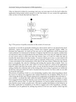
are typically implemented. (See Figure 4.3.)
4.6.6 10 M
BPS
E
THERNET
TO
100 M
BPS
F
AST
E
THERNET
M
IGRATION
Migration from one Ethernet variant to another is relatively straightforward. Fast
Ethernet products such as adapters, repeaters, stackable repeaters, and switches can
be integrated into a conventional 10 Mbps Ethernet network incrementally or all at once
to provide additional bandwidth and capacity for enhancing network performance.
0889Ch04Frame Page 158 Wednesday, April 17, 2002 3:03 PM
© 2002 by CRC Press LLC
4.7 FAST ETHERNET
4.7.1 IEEE 802.3
U
OR
F
AST
E
THERNET
S
PECIFICATION
Demand for higher transmission speeds culminated in the development of the Fast
Ethernet specification. Also called the IEEE 802.3u specification, Fast Ethernet, or
100 Mbps Ethernet, the Fast Ethernet specification employs the CSMA/CD process
for enabling transmission rates at 100 Mbps. The Fast Ethernet specification also
defines several transmission methods that vary in the cabling employed. Popular 100
Mbps configurations include 100BASE-T, 100BASE-T2, 100BASE-T4, 100BASE-
TX, and 100BASE-FX.
4.7.2 F
AST
E
THERNET
T
RANSMISSION
M
ETHODS
4.7.2.1 100BASE-T
100BASE-T or Fast Ethernet employs four pairs of UTP (Unshielded Twisted Pair)
Categories 3, 4, or 5 copper wires to facilitate baseband operations and transmissions
at 100 Mbps over network segments that extend to 100 meters. 100BASE-T subcat-
egories include 100BASE-T2, 100BASE-T4, and 100BASE-TX.
4.7.2.1.1 100BASE-T2
100BASE-T2 supports baseband operations and digital signal processing techniques
for enabling transmission via two pairs of Categories 3, 4, or 5 UTP copper wires
over network segments that extend to 100 meters. 100BASE-T configurations support
FIGURE 4.3
A switched Ethernet/Fast Ethernet network featuring router-supported WAN
links. Ethernet subnetworks provide connections to workgroups and power users.
Local Server
10/100 Switch
Fast Ethernet Switch
10/100 Switch
10Base-T Hubs
100 Mbps Switched 10 Mbps
Switched
100Mbps
WAN
Router
100 Mbps
Shared 10 Mbps
Shared 10 Mbps
Shared 10 Mbps
Server Farm
Workgroup 1
Workgroup 2
Workgroup 3
Local Server
100 Mbps
Switched
100Mbps
Switched 100 Mbps
Power User Group
Switched 100 Mbps
Specialized Process Groups
0889Ch04Frame Page 159 Wednesday, April 17, 2002 3:03 PM
© 2002 by CRC Press LLC
half-duplex and dual-duplex transmission by using two simplex or one-way links to
enable bi-directional services.
4.7.2.1.2 100BASE-T4
100BASE-T4 splits the data stream for enabling half-duplex baseband transmissions
via four pairs of Categories 3, 4, or 5 UTP copper wires in 100-meter segments.
100BASE-T4 is the half-duplex version of 100BASE-T.
4.7.2.1.3 100BASE-TX
100BASE-TX employs two pairs of STP or UTP Category 5 copper wires for linking
centralized hubs, switches, and network stations or nodes together in 100-meter
segments. It is important to also note that the maximum distance between two end-
stations over which 100BASE-TX transmissions are enabled is 400 meters.
100BASE-TX implementations support baseband operations and employ one pair
of copper wires to transmit data and the other pair of copper wires to receive data
at rates reaching 100 Mbps.
4.7.2.2 100BASE-FX
100BASE-FX installations employ two strands of multimode fiber optic cabling for
enabling full-duplex transmission via network segments that extend to 400 meters.
By using a version of the Fiber Data Distributed Interface (FDDI) Physical Layer
standard developed by the American National Standards Institute (ANSI), 100BASE-
FX also supports single-mode optical fiber solutions for enabling information trans-
port via network segments that extend to 5,000 meters.
4.7.3 F
AST
E
THERNET
S
WITCHES
10/100 Ethernet switches enable the development of a dual-mode network by sup-
porting 10 Mbps Ethernet and 100 Mbps Fast Ethernet operations. With the use of
10/100 Ethernet switches, only minor changes are required in the existing infrastruc-
ture to effectively migrate from 10 Mbps Ethernet to 100 Mbps Ethernet.
10/100 Ethernet switches work in concert with the installed Ethernet infrastruc-
ture. As a consequence, migration to a 100 Mbps Ethernet solution is readily
accomplished by replacing the 10BASE-T switch with a 100BASE-T switch. Fast
Ethernet switches with speed translation ports also support 10 Mbps Ethernet and
100 Mbps Ethernet implementations. Because the costs for 10 Mbps Ethernet
switches and 10/100 Ethernet switches are nearly identical, enterprises and organi-
zations typically employ 10/100 Ethernet switches to accommodate current and
projected applications.
Fast Ethernet switches interlink individual LANs between buildings into larger
configurations such as switched LANs (SLANs). These devices provide centralized
connection points for network servers and consolidate traffic in LAN installations
for improved network performance. Fast Ethernet backbone switches work in concert
with legacy equipment, support full-duplex transmissions, facilitate network man-
agement and advanced packet filtering functions, and enable interconnectivity
0889Ch04Frame Page 160 Wednesday, April 17, 2002 3:03 PM
© 2002 by CRC Press LLC
between Fast Ethernet LANs and Token Ring LANs to alleviate network congestion.
(See Figure 4.4.)
4.8 FAST ETHERNET STANDARDS ORGANIZATIONS
AND ACTIVITIES
4.8.1 F
AST
E
THERNET
A
LLIANCE
The Fast Ethernet Alliance promotes development of Fast Ethernet solutions that
are compatible with the CSMA/CD protocol endorsed in the original Ethernet
specification. This Alliance also supports the implementation of interoperable Ether-
net and Fast Ethernet products such as 10/100 Ethernet switches.
4.8.2 F
AST
E
THERNET
C
ONSORTIUM
Established in 1993, the Fast Ethernet Consortium performs scheduled testing of
IEEE 802.3u equipment and software to verify interoperability support, standards
conformance, and product quality. A vendor group, the Fast Ethernet Consortium
also benchmarks the capabilities of Fast Ethernet switches, hubs, routers, and other
internetworking products at the University of New Hampshire InterOperability Lab
(IOL). In addition, the Fast Ethernet Consortium evaluates Fast Ethernet functions
in research testbeds and actual networking environments.
FIGURE 4.4
A switched Ethernet departmental network that interworks with a university
Fast Ethernet backbone network.
Local Server
10/100 Switch
Fast Ethernet Switch
10/100
Intelligent Hub
10Base-T Hubs
100 Mbps Switched 10 Mbps
100Mbps
100 Mbps
Shared 10 Mbps
Shared 10 Mbps
Shared 10 Mbps
Workgroup 1
Workgroup 2
Workgroup 3
Local Server
100Mbps
to University Network
Power User Group
Server Farm
0889Ch04Frame Page 161 Wednesday, April 17, 2002 3:03 PM
© 2002 by CRC Press LLC
4.8.3 ATM FORUM
4.8.3.1 MultiProtocol-over-ATM (MPOA) Specification
Endorsed by the ATM Forum, the MultiProtocol-over-ATM (MPOA) specification
optimizes traffic throughput and supports ATM interoperability with Ethernet and
Fast Ethernet configurations, thereby enabling Ethernet and Fast Ethernet configu-
rations to benefit from ATM services. As an example, MPOA supports packet
exchange between Ethernet, Fast Ethernet, and Token Ring LANs via an ATM
backbone network.
MPOA also supports IP applications; streamlines the transmission process; and
transports voice, video, and audio signals to destination sites via ATM SVCs (Switched
Virtual Circuits). In addition, MPOA enables network traffic at Layer 3 or the Network
Layer of the OSI Reference Model to be switched at the Media Access Control (MAC)
Sublayer of the Data-Link Layer of the Ethernet protocol stack. The ATM Forum
MultiProtocol-over-ATM Working Group clarifies MPOA operations.
4.8.3.2 Routing Information Protocol (RIP)
The ATM Forum endorses the Routing Information Protocol (RIP). This protocol
establishes links between ATM subnetworks and Ethernet and Fast Ethernet networks
to support fast and dependable IP services.
4.8.4 FAST ETHERNET COMPETITOR TECHNOLOGIES
4.8.4.1 100VG-AnyLAN
4.8.4.1.1 100VG-AnyLAN Transmission
The 100VG-AnyLAN is an IEEE 802.5 specification for 100 Mbps LAN installations
that utilize either Fast Ethernet or Token Ring frames for transmission. The 100VG-
AnyLAN supports information transport via four pairs of Category 1, 3, 4, or 5
Unshielded Twisted Pair (UTP) copper cabling. In contrast to Ethernet and Fast
Ethernet utilization of CSMA/CD, 100VG-AnyLAN uses a demand-priority access
technique that eliminates the need to monitor the network for collisions.
4.8.4.1.2 100VG-AnyLAN Operations
In a 100VG-AnyLAN configuration, the hub or root controls network access. With
100VG-AnyLAN demand-priority operations, a network station or node seeking to
transmit signals submits a request to the hub. The hub immediately acknowledges
the request if the network is idle. Upon receiving the acknowledgment, the network
station initiates the transmission process by sending voice, video, and data to the
hub. When the hub receives more than one request concurrently, the hub uses a
round-robin technique to acknowledge each request in turn. High-priority requests
for transmission involving time-sensitive applications such as videoconferencing are
serviced ahead of normal-priority requests for transport of time-insensitive data such
as e-mail and file transfers. Generally, the hub does not grant priority access to a
port more than twice in a row, thereby enabling the fair participation of all network
stations in LAN activities.
0889Ch04Frame Page 162 Wednesday, April 17, 2002 3:03 PM
© 2002 by CRC Press LLC
100VG-AnyLAN solutions employ hubs that are more costly than centralized
hubs used with 100BASE-T installations. In addition, 100VG-AnyLAN is limited
to provisioning rates at 100 Mbps because this technology does not support full-
duplex transmissions. By contrast, 100BASE-T supports full-duplex transmissions
at 200 Mbps and enables straightforward migration to gigabit rates enabled by
Gigabit Ethernet technology.
Developed by Hewlett-Packard, 100VG-AnyLAN was expected to be a strong
contender to Fast Ethernet in the LAN domain. In comparison to 100VG-AnyLAN,
Fast Ethernet dominates the present-day marketplace.
4.8.4.2 Fiber Data Distributed Interface (FDDI)
4.8.4.2.1 FDDI Capabilities
Initially standardized in the ANSI (American National Standards Institute) X3T9.5
specification released in 1989, the international FDDI specification is also known
as ISO (International Standards Organization) 9314. FDDI supports transmissions
via fiber optic cabling. In addition, FDDI also works with standard twisted pair
copper cabling in enabling interconnectivity. The copper version of FDDI is called
Copper Distributed Data Interface (CDDI).
Fiber Distributed Data Interface (FDDI) is an ANSI standards-compliant tech-
nology for 100 Mbps Token Ring LANs. Internetworking devices such as routers,
bridges, and switches foster FDDI interoperability with star and bus LAN topologies.
In addition, FDDI serves as a fiber optic backbone for LAN installations.
4.8.4.2.2 FDDI Transmission
The maximum frame size supported by FDDI includes 4500 bytes, with 4478 bytes
allocated for the payload or information field. The remaining bytes, including a
header field and a trailer field, ensure dependable information delivery. FDDI utilizes
a timed token passing scheme for network access. A token consists of a three-octet
FDDI frame. By contrast, the IEEE 802.5 Token Ring LAN specification supports
utilization of a priority reservation token access methodology.
4.8.4.2.3 FDDI Operations
FDDI LAN installations employ a dual-ring topology. The main ring utilizes dual-
attachment stations to support a secondary ring that enables operations in case of a
failed station or fiber cut. Each ring provisions network service for up to 500 nodes.
By using repeaters, each ring supports network operations for 1000 nodes. In an FDDI
LAN, FDDI protocol analyzers monitor networking activities and the Simple Network
Management Protocol (SNMP) enables seamless networking operations.
FDDI WANs (Wide Area Networks) facilitate information transport over dis-
tances that extend to two kilometers via multimode optical fiber. With single-mode
optical fiber, FDDI WAN configurations enable transmissions at distances that extend
to 10 kilometers.
FDDI is a flexible internetworking technology that interoperates with Ethernet,
Fast Ethernet, ATM, and satellite networking solutions. Translational and encapsu-
lating bridges that foster interconnectivity between LAN media featuring dissimilar
MAC (Medium Access Control) protocol sublayers enable FDDI and Gigabit Ethernet
0889Ch04Frame Page 163 Wednesday, April 17, 2002 3:03 PM
© 2002 by CRC Press LLC
interoperability. FDDI-to-Gigabit Ethernet migration is accomplished by replacing
FDDI hubs, concentrators, or routers with Gigabit Ethernet switches and the instal-
lation of new Gigabit Ethernet interfaces. This process enables enterprises to retain
investments in the optical fiber infrastructure while also increasing the aggregate
bandwidth substantially for the upgraded network segments.
FDDI was expected to be the enabler of next-generation LAN configurations.
However, in contrast to Fast Ethernet solutions, FDDI installations are considerably
more expensive to implement and maintain. Moreover, FDDI installations are limited
in supporting high-performance multimedia applications.
In contrast to FDDI, Fast Ethernet implementations are affordable and extend-
ible, operate over twisted copper wire pairs, and support backward compatibility
with in-place 10 Mbps Ethernet LANs. These factors also contributed to the selection
of the Fast Ethernet specification or IEEE 802.3u as an extension to the IEEE 802.3
standard.
4.8.4.2.4 FDDI and FDDI II (FDDI, Phase 2)
FDDI II is based on the original FDDI format. As with FDDI, FDDI II technology
supports network operations at rates reaching 100 Mbps. FDDI II was designed
specifically to support multimedia applications and enable voice and video transport.
FDDI II solutions use a synchronous bandwidth allocation scheme that enables
network nodes to reserve bandwidth for regularly transmitted, delay-sensitive net-
work traffic. Because FDDI II technology is ineffective in supporting broadcast-
quality video, FDDI II solutions are used infrequently.
4.9 GIGABIT ETHERNET TECHNICAL FUNDAMENTALS
As with its Ethernet and Fast Ethernet predecessors, Gigabit Ethernet technology
works in wireless and wireline environments. A multifunctional communications
technology, Gigabit Ethernet significantly expands available bandwidth for enabling
interactive, high-performance multimedia applications. In comparison to Fast Ether-
net, Gigabit Ethernet increases the rates at which data are transmitted by a factor of
ten. In contrast to its predecessor, Gigabit Ethernet employs the physical signaling
scheme described in the Fibre Channel specification for enabling packet transmis-
sion.
4.9.1 GIGABIT ETHERNET FUNCTIONS
Gigabit Ethernet networks utilize the underlying infrastructure established with
Ethernet and Fast Ethernet specifications. As a consequence, Gigabit Ethernet
enables a straightforward migration path to higher performance levels without dis-
rupting in-place networking operations. Generally viewed as an extension of Ethernet
and Fast Ethernet, Gigabit Ethernet technology ensures seamless interworking with
Ethernet and Fast Ethernet services and operations.
Gigabit Ethernet also employs the same protocols, transmission schemes, frame
size, frame format, flow control procedures, and access methods as Ethernet and
Fast Ethernet. Therefore, the need for complex emulation and translation techniques
0889Ch04Frame Page 164 Wednesday, April 17, 2002 3:03 PM
© 2002 by CRC Press LLC
to support migration from Ethernet and Fast Ethernet implementations to Gigabit
Ethernet solutions is eliminated.
4.9.2 GIGABIT ETHERNET ARCHITECTURE
Gigabit Ethernet Physical Layer specifications support half-duplex and full-duplex
operations; gigabit transmissions over two strands of optical fiber or two pairs of
shielded twisted copper wires; and encoding schemes defined by the ANSI Fibre
Channel standard. The network topology for Gigabit Ethernet conforms to the
conventional specifications for Ethernet and Fast Ethernet. In conjunction with
Ethernet and Fast Ethernet, Gigabit Ethernet employs Layer 1 or the Physical Layer
and the Media Access Control (MAC) Sublayer of Layer 2 or the Data-Link Layer
for information transport. Additionally, Gigabit Ethernet works in conjunction with
upper layer protocols such as IP (Internet Protocol) and TCP (Transmission Control
Protocol). In terms of the OSI Reference Model, IP and TCP utilize the Transport Layer
or Layer 4 and the Network Layer or Layer 3 for enabling communications services
between applications.
4.9.3 GIGABIT ETHERNET OPERATIONS
Gigabit Ethernet implementation is basically a replication of deployment procedures
associated with its predecessors. Moreover, in-place Ethernet and Fast Ethernet
management systems and equipment function in concert with Gigabit Ethernet
management systems, services, and applications, thereby enabling cost-effective
migration to advanced Gigabit Ethernet solutions.
Early Gigabit Ethernet implementations employed optical fiber for supporting
full-duplex transmissions and facilitating building-to-building LAN interconnec-
tions. As evidenced by the ratification of the Gigabit Ethernet over copper cabling
standard by the IEEE, Gigabit Ethernet also works effectively with Unshielded
Twisted Pair (UTP) in delivering services to the desktop.
As with previous Ethernet generations, Gigabit Ethernet is scalable and extend-
ible, augments functions of in-place networks, and enables a broad array of appli-
cations. In the LAN arena, Gigabit Ethernet supports links between servers and
switches and interconnects clusters of servers, server farms, and network segments.
In addition, Gigabit Ethernet provisions high-speed connections between buildings
and supports transmissions ranging from 10 Mbps to 1000 Mbps or 1 Gbps and
higher rates. Moreover, Gigabit Ethernet installations are less costly than ATM in
terms of implementation, operations, administration, and maintenance.
It is important to note that Gigabit Ethernet and its predecessors are subject to
distance and signal constraints. Transmission impairments result in attenuation or
signal power loss, near-end crosstalk (NEXT), and latencies in signal transport.
4.9.4 IEEE 802.3Z OR FIBER OPTIC GIGABIT ETHERNET IMPLEMENTATIONS
The IEEE 802.3z specification for extending Gigabit Ethernet functions into the
optical fiber environment was ratified in 1998. Endorsed by the IEEE 802.3z Gigabit
0889Ch04Frame Page 165 Wednesday, April 17, 2002 3:03 PM
© 2002 by CRC Press LLC
Ethernet Task Force, the Gigabit Ethernet Alliance, and the IEEE Standards Committee,
the IEEE 802.3z standard defines Ethernet operations at rates of 1000 Mbps or 1
Gbps for half-duplex transmissions and Ethernet operations at 2000 Mbps or 2 Gbps
for full-duplex transmissions.
The Gigabit Ethernet IEEE 802.3z standard also clarifies capabilities of trans-
ceivers that operate in conjunction with single-mode and multimode optical fiber
plants and supports ongoing utilization of in-place optical fiber links that intercon-
nect multiple buildings in campus LANs. The role of optical components such as
optical lasers in transporting data-, voice-, and video-over-optical fiber is also indi-
cated.
4.9.4.1 Gigabit Media Independent Interface (GMII)
The IEEE 802.3z specification also describes Gigabit Media Independent Interface
(GMII) services. The GMII enables interconnectivity of MAC Sublayer protocol
devices with the Physical Layer or Layer 1 of the OSI Reference Model. Further-
more, the GMII supports half-duplex and full-duplex transmissions, multivendor
interoperability, and backward compatibility with Ethernet and Fast Ethernet instal-
lations. In addition, the GMII enables virtual independent pathways or channels for
data transmission and reception.
4.10 GIGABIT ETHERNET SOLUTIONS
Based on the work of the IEEE 802.3z Gigabit Ethernet Task Force and the Gigabit
Ethernet Alliance and ratified by the IEEE, the Gigabit Ethernet standard defines
network interfaces, repeater operations, topologies, and capabilities of 1000BASE-
SX and 1000BASE-LX configurations. The IEEE 802.3z Gigabit Ethernet Task
Force and the Gigabit Ethernet Alliance also clarify features and functions of
1000BASE-LH and 1000BASE-CX networks.
4.10.1 1000BASE-SX
Based on the Fibre Channel signaling standard, 1000BASE-SX describes Gigabit
Ethernet short wavelength solutions. In supporting full-duplex mode transmissions,
each 1000BASE-SX network segment enables transmission via multimode optical
fiber at distances that extend to 275 meters. In addition, each 1000BASE-SX network
segment supports full-duplex information transport over single-mode optical fiber
at distances that extend to 550 meters.
4.10.2 1000BASE-LX
1000BASE-LX describes long wavelength Gigabit Ethernet solutions. With full-
duplex mode operations, each 1000BASE-LX network segment facilitates transmis-
sions via single-mode optical fiber at distances that reach 5000 meters. In enabling
full-duplex operations over multimode optical fiber, each 1000BASE-LX network seg-
ment enables voice, video, and data transport at distances that extend to 550 meters.
0889Ch04Frame Page 166 Wednesday, April 17, 2002 3:03 PM
© 2002 by CRC Press LLC
4.10.2.1 Differential Mode Delay (DMD)
The IEEE 802.3z Gigabit Ethernet Task Force also developed a solution for reducing
the adverse impact of Differential Mode Delay (DMD), a condition that generates
jitter in LED (Light Emitting Diode) installations supporting transmissions via
multimode optical fiber. According to this Task Force, the utilization of conditioners
with 1000BASE-LX and 1000BASE-SX configurations and dispersal of light pulses
evenly through every lightpath or channel in each network segment resolves DMD
transmission disruptions.
4.10.3 1000BASE-LH
Supported by the IEEE 802.3z Gigabit Ethernet Task Force and the Gigabit Ethernet
Alliance, 1000BASE-LH defines long-haul fiber optic Gigabit Ethernet Metropolitan
Area Network (MAN) solutions that operate in multivendor urban environments.
4.10.4 1000BASE-CX
Developed by the IEEE 802.3z Gigabit Ethernet Task Force and the Gigabit Ethernet
Alliance, 1000BASE-CX refers to Gigabit Ethernet transmission over Category 5
Unshielded Twisted Pair (UTP). Each 1000BASE-CX network segment enables full-
duplex operations at distances that extend to 25 meters.
4.10.5 IEEE 802.3AB OR 1000BASE-T
The IEEE ratified the IEEE 802.3ab standard, also known as 1000BASE-T, in 1999.
This standard is based on research efforts sponsored by the Gigabit Ethernet Alliance.
To verify 1000BASE-T capabilities, tests benchmarking the performance of Gigabit
Ethernet over copper wiring were conducted by Gigabit Ethernet Alliance partici-
pants, including Alteon Web System, Extreme Networks, 3Com, and Sun Microsys-
tems, at the Silicon Valley Networking Lab (SVNL). These tests evaluated Gigabit
Ethernet performance in seamlessly enabling interoperability, full-motion video,
groupware applications, and remote file transfers over Category 5 UTP (Unshielded
Twisted Pair). Findings contributed to IEEE endorsement of the 1000BASE-T Giga-
bit Ethernet-over-copper wire specification.
1000BASE-T solutions utilize four pairs of Category 5 UTP copper wires for
enabling transmissions up to 100 meters over a single network segment. Each copper
pair supports throughput at 250 Mbps for enabling a total transmission of 1000 Mbps
or 1 Gbps in half-duplex mode and 2000 Mbps or 2 Gbps in full-duplex mode.
Because 1000BASE-T installations work in conjunction with the installed Category
5 wireline infrastructure, the need to rewire ceilings, walls, or raised floors is
eliminated.
1000BASE-T is compatible with Ethernet and Fast Ethernet technologies and
works in concert with 56 Kbps (Kilobits per second) modems. A high-performance
networking solution, 1000BASE-T also enables innovative desktop applications and
high-speed server connectivity. Techniques employed by 1000BASE-T for eliminat-
ing signal degradation resulting from signal attenuation, echo, impulse noise, and
0889Ch04Frame Page 167 Wednesday, April 17, 2002 3:03 PM
© 2002 by CRC Press LLC