Fundamentals of Spread Spectrum Modulation phần 8 pot
Bạn đang xem bản rút gọn của tài liệu. Xem và tải ngay bản đầy đủ của tài liệu tại đây (303.55 KB, 10 trang )
book Mobk087 August 3, 2007 13:15
64 FUNDAMENTALS OF SPREAD SPECTRUM MODULATION
r
For a linear code the sum of any two codewords is also a codeword. This means that we
can characterize the error-correction capability of a linear code by its weight distribution;
this is the set A
d
of all codewords a distance d from the all-0s codeword. For example,
a code with weight distribution A
3
= 7, A
4
= 7, and A
7
= 1 has seven codewords
distance 3, seven codewords distance 4, and one codeword distance 7 from the all-0s
codeword.
r
A cyclic code is one where the codeword are cyclic shifts of each other.
It can be shown that the optimum decoding rule is the following:
r
For hard decisions (i.e., 1-0 decisions), choose as the transmitted codeword the one
closest to the received data vector with distance measured in the Hamming sense.
r
For soft decision information, choose as the transmitted codeword the closest to the
received data vector with distance measured in the Euclidian sense; i.e., choose x
m
to
minimize
n
j=1
y
j
− x
m
j
2
, (7.1)
where y =
[
y
1
, y
2
, ,y
m
]
is the received data vector.
Bit error probabilities for general linear codes are difficult to compute exactly. For
bounded distance decoders (i.e., decoders that can correct up to E errors and no more), it
has been argued [14] that the bit error probability is bounded by
P
b
=
1
k
n
i=E+1
min
[
k, i + E
]
n
i
p
i
(
1 − p
)
n−i
, (7.2)
where p is the probability of a symbol error in the received codeword. For the jamming channels
of the previous section, p would be one of the bit error probability expressions given there.
7.1.1 BCH Block Codes [16]
An example family of block codesisthe Bose—Chaudhuri–Hocquenghem (BCH) codes,which
are linear cyclic codes. Nonbinary BCH codes exist, but we will limit our attention to only the
binary. The block length for binary BCH codes is always n = 2
m
−1, m ≥ 3 an integer. The
number of errors that can be corrected is bounded by t <
(
2
m
−1
)
/2 and it is always true
that n − k ≤ mt. Specific values for t and k are given in Table 11. Approximate bit error
probabilities versus E
b
/N
0
in Gaussian noise channels can be computed using (7.2) by using
the appropriate bit error probability expression from Table 2. In doing so, it is important to
remember to replace E
b
/N
0
in these expressions with RE
b
/N
0
, where R = k/n to account
book Mobk087 August 3, 2007 13:15
FUNDAMENTALS OF SPREAD SPECTRUM MODULATION 65
for the increase in code symbol rate required to keep the overall bit rate the same (n code
symbols are required for each k bits sent through the channel). To determine coded bit error
rate in spread spectrum with jamming, the same procedure is used, but the appropriate bit error
probability expression derived in Section 5.4 is used instead. This will be done later after other
coding techniques are discussed.
7.1.2 Reed–Solomon Block Codes [16]
Another important family of block codes are Reed–Solomon codes. They are nonbinary block
codes that have found important applications in space communications and compact disc tech-
nology, among other applications. Reed–Solomoncodes are particularlyeffective in applications
where errors tend to occur in bursts.
Reed–Solomon codes use alphabets having 2
m
symbols,
{
0, 1, , 2
m
−1
}
, with block
length n = 2
m
−1. The codes can correct up to e
0
errors with the number of parity symbols
being n −k = n −2e
0
= 2
m
−1 − 2e
0
. The minimum distance of this code family is d
min
=
2e
0
+1, where the Hamming distance between nonbinary codewords is defined to be the
number of positions in which the codewords differ. Reed–Solomon codes are often used in
channels that are nonbinary, for example, ones where M-ary FSK is the modulation scheme
of choice (if 8-FSK is used, it would be convenient to choose an m =3 Reed–Solomon code).
If used in a binary channel, bits may be grouped to form m-bit blocks. In this case, the Reed–
Solomon code can be thought of as accepting k
= km information bits and mapping them
into channel symbol blocks of length n
= nm binary channel symbols. Thus, the rate of the
Reed–Solomon code is
R =
k
n
=
k
n
=
2
m
−1 − 2e
0
2
m
−1
(7.3)
or
e
0
=
(
1 − R
)
2
m
−1
2
. (7.4)
The probability of bit error for Reed–Solomon codes is over bounded by
P
b
≤
2
m
−1
i=e
0
+1
i
2
(
2
m
−2
)
2
m
−1
i
p
i
s
(
1 − p
s
)
2
m
−1−i
, (7.5)
where, for noncoherent MFSK, the symbol error probability is given by
p
s
=
M−1
k=1
(
−1
)
k+1
k + 1
M −1
k
exp
−k
k + 1
E
s
N
0
(7.6)
book Mobk087 August 3, 2007 13:15
66 FUNDAMENTALS OF SPREAD SPECTRUM MODULATION
with the symbol energy-to-noise spectral density ratio for Gaussian noise being given by
E
s
/N
0
= mR
(
E
b
/N
0
)
which accounts for the code rate R = k/n and the fact that m binary
bits are associated with one 2
m
-ary symbol. If a binary modulation scheme is used, (7.6) would
be replaced by
p
s
= 1 −
(
1 − p
)
m
, (7.7)
where p is the probability of bit error for the appropriate binary modulation scheme. For
example, for BPSK in white Gaussian noise it is
p = Q
2RE
b
N
0
. (7.8)
Results forspread spectrum communicationsystem performance in jamming usingReed–
Solomon codes will be presented later.
7.2 Convolutional Codes
Convolutional codes differ from block codes in that the information bits are not grouped into
blocks for encoding,but rather a linear shift-register circuit is used tomap a continuous sequence
of input symbols (bits) into a continuous sequence of output symbols (bits). The principle of
keeping the allowed codewords separated in Hamming distance as much as possible still holds
as it does for block codes. A convolutional code can be characterized in various ways, including
an encoder block diagram, its code generators, a state transition diagram, or a trellis diagram.
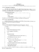
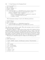
Figure 31 shows an example block diagram of a convolutional encoder, where the adders are
modulo-2 and the input information bits are clocked in at the left in time sequence. For each
input bit, two output bits are generated because the switch on the right-hand side first is
in the upper position and then flips to the lower position for each input bit. For the input
{
101
}
⇒ 1 + D
2
, for example, we have at the upper adder output
1 + D
2
1 + D + D
2
= 1 + D + D
3
+ D
4
⇒
{
11011
}
and we have at the lower adder output
1 + D
2
1 + D
2
= 1 + D
4
⇒
{
10001
}
,
where the arithmetic is modulo-2. Sampling a bit from the upper leg and then from the
lower gives output encoded sequence
{
1110001011
}
. We will not exhibit the state transition
diagram or the trellis diagram for this encoder. For a rate-1/3 code, there would be three adders
in the block diagram and the output would sample sequentially from the outputs of these
three adders. From the encoder block diagram, it should be clear that convolutional codes are
linear.
book Mobk087 August 3, 2007 13:15
FUNDAMENTALS OF SPREAD SPECTRUM MODULATION 67
FIGURE 31: Block diagram of a rate-1/2 convolutional encoder.
Maximum likelihood decoding of a convolutionally encoded sequence in noise is per-
formed by the Viterbi algorithm. Performance of a convolutional code is analyzed by finding the
probability of deviating from the correct path through the trellis and determining the resulting
number of bit errors. The probability of bit error for a convolutional code is over bounded
by
P
b
<
∞
k=d
free
c
k
P
k
, (7.9)
where d
free
, called the free distance, is the Hamming distance between the all-zeros path in the
trellis and the minimum-length path deviating from it, and
P
k
=
k
e=k/2+1
k
e
p
e
(
1 − p
)
k−e
+
1
2
p
k/2
(
−p
)
k/2
, k even
P
k
=
k
e=
(
k+1
)
/2
k
e
p
e
(
1 − p
)
k−e
, k odd
p = hard decision channel error probability
(7.10)
for hard (1-0) channel decisions, and
P
k
= Q
2kRE
b
N
0
(7.11)
for soft channel decisions assuming BPSK signaling in additive Gaussian noise backgrounds.
The constants c
k
can be found by computer simulation for a given convolutional code and are
listed in Tables 12 and 13 for the best rate-1/2 and rate-1/3 codes, respectively.
book Mobk087 August 3, 2007 13:15
68 FUNDAMENTALS OF SPREAD SPECTRUM MODULATION
TABLE 11: Abbreviated List of BCH Code Parameters [16]
nktnktnkt
31 21 2 255 247 1 511 502 1
16 3 231 3 484 3
11 5 223 4 466 5
63 57 1 215 5 448 7
* 45 3 207 6 430 9
& 30 6 * 191 8 412 11
24 7 163 12 * 385 14
% 16 11 147 14 358 18
127 120 1 & 131 18 322 22
106 3 115 21 & 259 30
* 99 4 99 23 211 41
78 7 87 26 175 46
& 64 10 % 63 30 % 130 55
50 13 55 31 103 61
36 15 45 43 67 87
% 2921 2947 31109
8 31 13 59 10 121
∗rate 3/4.
& rate 1/2.
% rate 1/4.
7.3 Example System Performances for Spread Spectrum Systems with Coding
Operating in Jamming Environments
In this section, three example systems are considered to show the improvement afforded by
coding in jammed spread spectrum systems.
book Mobk087 August 3, 2007 13:15
FUNDAMENTALS OF SPREAD SPECTRUM MODULATION 69
TABLE 12: Best Rate-1/2 Convolutional Codes and Their Partial Weight Structure [16]
CONSTR. CODE FREE
LENGTH, GENER- DIST-,
ν ATORS ANCE c
k
FOR d =
(OCTAL) d
f
d
f
d
f
+1 d
f
+2 d
f
+3 d
f
+4 d
f
+5 d
f
+6 d
f
+7
3 (7, 5) 5 1 4 12 32 80 192 448 1024
4 (15, 15) 6 2 7 18 49 130 333 836 2069
5 (35, 23) 7 4 12 20 72 225 500 1,324 3680
6 (75, 53) 8 2 36 32 62 332 701 2,342 5503
7 (171, 133) 10 36 0 211 0 1404 0 11,633 0
8 (371, 247) 10 2 22 60 148 340 1008 2,642 6748
9 (753, 561) 12 33 0 281 0 2179 0 15,035 0
TABLE 13: Best Rate-1/3 Convolutional Codes and Their Partial Weight Structure [16]
CONSTR. CODE FREE
LENGTH, GENER- DIS-
ν ATORS TANCE, c
k
FOR d =
(OCTAL) d
f
d
f
d
f
+1 d
f
+2 d
f
+3 d
f
+4 d
f
+5 d
f
+6 d
f
+7
3 (7, 7, 5) 8 3 0 5 0 58 0 201 0
4 (17, 15, 13) 10 6 0 6 0 58 0 118 0
5 (37, 33, 25) 12 12 0 12 0 56 0 320 0
6 (75, 53, 47) 13 1 8 26 20 19 62 86 204
7 (171, 145, 133) 14 1 0 20 0 53 0 184 0
8 (367, 331, 225) 16 1 0 24 0 113 0 287 0
book Mobk087 August 3, 2007 13:15
70 FUNDAMENTALS OF SPREAD SPECTRUM MODULATION
0 5 10 15 20 25 30 35
10
-8
10
-7
10
-6
10
-5
10
-4
10
-3
10
-2
10
-1
10
0
(P/J)(W/R), dB
P
b
n = 63, k = 16, t = 11; R
c
= 0.254
n = 127, k = 29, t = 21; R
c
= 0.228
Uncoded; W/R = W/R
s
= 1000
BCH coded; W/R
s
= (W/R)R
c
FIGURE 32: Rate-1/4 BCH codes to improve the performance of FH/DPSK in optimum tone jam-
ming.
Example 11. Consider a FH/DPSK spread spectrum system in worst-case tone jamming
with W/R = 1000. Investigate the use of rate-1/4 and rate-1/2 BCH coding to improve
performance.
Solution: The channel symbol error probability is given by (6.18). The bit rate and symbol
rate are related by R
s
= nR/k. A MATLAB program for computing performance, based on
(7.2), was used to obtain the results shown in Fig. 32 for codes of approximately rate 1/4 and in
Fig. 33 for codesof approximately rate1/2. Note that the rate-1/4 codes actually outperform the
rate-1/2 codes due to their greater error-correction capability. This is in spite of the fact that
W/R
s
is less for the rate-1/4 codes than for the rate-1/2 codes (i.e., the former case provides
less protection due to spreading than the latter).
Example 12. Consider a FH/DPSK spread spectrum system in worst-case tone jam-
ming with W/R = 1000. Investigate the use of Reed–Solomon coding to improve perfor-
mance.
book Mobk087 August 3, 2007 13:15
FUNDAMENTALS OF SPREAD SPECTRUM MODULATION 71
0 5 10 15 20 25 30 35
10
-8
10
-7
10
-6
10
-5
10
-4
10
-3
10
-2
10
-1
10
0
(P/J)(W/R), dB
P
b
n = 63, k = 30, t = 6; R
c
= 0.476
n = 127, k = 64, t = 10; R
c
= 0.504
Uncoded; W/R = W/R
s
= 1000
BCH coded; W/R
s
= (W/R)R
c
FIGURE 33: Rate-1/2 BCH codes to improve the performance of FH/DPSK in optimum tone jam-
ming.
Solution: The channel symbol error probability is given by (6.18). A MATLAB program for
computing performance, based on (7.5), was used to produce the plots given in Fig. 34. Again
note that the rate-1/4 code slightly outperforms the rate-1/2 code [at high
(
P/J
)(
W/R
)
]due
to its greater error-correction capability. This is in spite of the fact that W/R
s
is less for the
rate-1/4 code than for the rate-1/2 code.
Example13. Consider a FH/DPSK spread spectrum system in worst-case tone jamming with
W/R = 1000. Investigate the use of convolutional coding to improve performance.
Solution: The channel symbol error probability is given by (6.18). A MATLAB program for
computing performance, based on the bound of (7.9), was used to produce the results given
in Fig. 35 for the rate-1/2 code and in Fig. 36 for the rate-1/3 code. Since the modulation is
binary DPSK, bits were blocked into 6-bit blocks with the symbol error probability computed
from (7.7). The code symbol energy is related to the bit energy by E
s
= kE
b
/n.
book Mobk087 August 3, 2007 13:15
72 FUNDAMENTALS OF SPREAD SPECTRUM MODULATION
0 5 10 15 20 25 30 35
10
-8
10
-7
10
-6
10
-5
10
-4
10
-3
10
-2
10
-1
10
0
(P/J)(W/R), dB
P
b
P
b
for FH/DPSK with Reed Solomon coding
e
0
= 15; W/R
s
= 524; R
c
= 0.524
e
0
= 23; W/R
s
= 270; R
c
= 0.27
Uncoded; W/R = 1000
RS coded; n = 63 (m = 6)
FIGURE 34: Use of Reed-Solomon coding to improve the performance in FH/DPSK with optimum
tone jamming.
7.4 Summary
Although the penalties imposed by optimized jammers can be very severe, the above examples
have shown that both block and convolutional coding can be used to combat much of the
performance degradation imposed by jamming. It is emphasized that an implicit assumption
in the use of such codes, which work most effectively if the errors are randomly distributed, is
that any tendency for the errors to be bunched is combated by use of appropriately designed
interleaving at the transmitter and corresponding de-interleaving at the receiver. The results
given in Figs. 32–36 indicate that improvements on the order of 15–20 dB can be expected at
bit error probabilities of 10
−3
or lower.
8 PERFORMANCE IN MULTIPLE USER ENVIRONMENTS
As discussed in conjunction with Fig. 1, more than one user occupying the same time–frequency
space can exist simultaneously in a spread spectrum system if their respective spreading codes
have low cross-correlation between them. This property of spread spectrum systems is called
code-division multiple-access (CDMA) capability. To investigate some of the aspects of this
book Mobk087 August 3, 2007 13:15
FUNDAMENTALS OF SPREAD SPECTRUM MODULATION 73
0 5 10 15 20 25 30 35 40 45 50
10
-8
10
-7
10
-6
10
-5
10
-4
10
-3
10
-2
10
-1
(P/J)(W/R), dB
P
b
P
b
for FH/DPSK with rate-1/2 convolutional coding in optimized tone jamming
ν
= 5
ν
= 7
ν
= 9
Uncoded; W/R = 1000
Conv coded; R = 0.5; W/R
s
= 500
FIGURE 35: Rate-1/2 convolutional coding to improve performance of FH/DPSK in optimized tone
jamming.
capability of spread spectrum systems, consider the simplified block diagram of Fig. 37, which
represents a baseband version of K simultaneous users transmitting data streams by using
spreading codes, presumably well chosen so that their mutual correlations are low. The different
delays account for possible differences in propagation times for different users. AWGN is
introduced primarily by the receiver front end of the intended receiver (in this case that of user
1 who correlates with its code and integrates over the bit interval). The received signal for user
1 is written as
y
(
t
)
= A
1
d
1
(
t −τ
1
)
c
1
(
t −τ
1
)
+
K
k=2
A
k
d
k
(
t −τ
k
)
c
k
(
t −τ
k
)
+n
(
t
)
, (8.1)
where A
k
and τ
k
, k = 1, 2, ,K, represent the amplitude and delay, respectively, for the kth
user. Assuming perfect synchronization of the local code for user 1, we can take τ
1
= 0and