Validation of Communications Systems with SDL phần 3 pptx
Bạn đang xem bản rút gọn của tài liệu. Xem và tải ngay bản đầy đủ của tài liệu tại đây (575.28 KB, 34 trang )
Interactive Simulation 49
4.2.2.3 Play the other scenarios
Once the DLC connection is established (if not, play the scenario described in Section 4.2.2.2),
continue the simulation, playing the following three scenarios (important: play them in sequence,
i.e. never reinitialize the Simulator):
A. Simulate XID, described in Figure 3.4: send signal L
SetParmReq to << Block DLCa >>
dispatch,pressGo and select 1/*
No
*/; send signalL SetParmResp to << Block DLCb >>
dispatch,pressGo and select 1/*
No
*/; check that the MSC trace is compliant with
Figure 3.4.
B. Simulate data transfer from A to B, described in Figure 3.6: send signal L
DataReq with
parameters 0 and 86 to << Block DLCa >> dispatch,pressGo,select1/*
No
*/.
C. Simulate DLC release, described in Figure 3.8: send signal L
ReleaseReq with parameter
0 to << Block DLCa >> dispatch,pressGo and select 1/*
No
*/ two times.
D. Save the simulation commands into the file test1.com, as indicated previously (Log > Save
Input History), because you will need it later.
E. Open the file test1.com with a text editor, and if necessary add a return in all the lines like:
Go 1 /* "No" */
Next-Transition 1 /* "No" */
to split them:
Go
1 /* "No" */
Next-Transition
1 /* "No" */
Remove the two lines:
Define-MSC-Trace-Channels on
Start-Interactive-MSC-Log 0
Here is the content of test1.com:
Set-GR-Trace 1
Next-Transition
Next-Transition
Next-Transition
Next-Transition
Output-To L_EstabReq (0) <<Block DLCa>> dispatch
Next-Transition
Next-Transition
Next-Transition
1 /* "No" */
Next-Transition
Output-To L_EstabResp <<Block DLCb>> dispatch
Next-Transition
50 Validation of Communications Systems with SDL
Next-Transition
Next-Transition
1 /* "No" */
Next-Transition
Next-Transition
Output-To L_SetparmReq <<Block DLCa>> dispatch
Go
1 /* "No" */
Output-To L_SetparmResp <<Block DLCb>> dispatch
Go
1 /* "No" */
Output-To L_DataReq (0, 86) <<Block DLCa>> dispatch
Go
1 /* "No" */
Output-To L_ReleaseReq (0) <<Block DLCa>> dispatch
Go
1 /* "No" */
1 /* "No" */
Save the file and close the text editor. Do not exit from the Simulator.
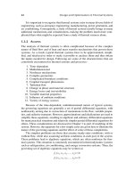
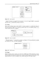
4.2.2.4 Generate a black box MSC
The MSC generated in Figure 4.13 contains all the model process instances. You will now
generate a more abstract “black box” MSC, containing only the blocks (DLCa, dataLink and
DLCb), to validate the external behavior of the system:
A. In the Simulator, select File > Restart and press OK .
B. Type the command Define-MSC-Trace-Channels on (or type d-m-t-c on)togettwoenvi-
ronment instances.
C. Select Trace > MSC Level: Set:aSelect Unit name window appears, select System V76test
and press OK :aSelect Trace value window appears, select 3/*Blocktrace*/ and press OK.
D. Select Trace > MSC Trace: Start: select 0 /* Basic MSC */ and press OK.
E. Select Execute > Command Script, choose test1.com and press OK : the Simulator executes
the commands contained in test1.com, and the MSC trace contains only blocks, instead of
processes, as illustrated in Figure 4.14.
F. Rename the MSC: in the MSC Editor, type test1 instead of SimulatorTrace.
G. Save the MSC: in the MSC Editor, select File > Save As, navigate to the desired directory,
enter test1.msc and press OK.
H. Exit from the Simulator.
4.2.3 Detect a bug in the SDL model
4.2.3.1 Check the number of retransmissions
You will check that the retransmission of SABME occurs a maximum of three times after
its first transmission, as specified in Section 3.2.3. For that, you will generate an MSC trace
Interactive Simulation 51
DLCb_3
block
DLCb
DLCa_2
block
DLCa
dataLink_1
block
dataLink
DLCaSU
Release of
DLC number 0:
Transfer of data
86 through DLC
number 0:
Exchange
identification
(XID):
DLC number 0
established.
MSC Test1
L_ReleaseInd
(0)
L_ReleaseInd
(0 )
V76frame
(UA : (. 0 .) )
V76frame
(UA : (. 0 .) )
V76frame
( DISC : (. 0 .) )
V76frame
( DISC : (. 0 .))
L_ReleaseReq
(0)
L_DataReq
(0, 86)
V76frame
(I : (. 0, 86, 15 .) )
V76frame
( I : (. 0, 86, 15 .))
L_DataInd
( 0, 86)
V76frame
( XIDcmd : 0)
V76frame
( XIDcmd : 0 )
L_SetparmInd
L_SetparmResp
V76frame
(XIDresp : 0 )
V76frame
( XIDresp : 0)
L_SetparmConf
L_SetparmReq
L_EstabReq
(0)
L_EstabConf
(0 )
V76frame
(UA : (. 0 .) )
V76frame
( UA : (. 0 .) )
V76frame
(SABME : (. 0 .))
L_EstabResp
L_EstabInd
(0)
V76frame
(SABME : (. 0 .))
DLCbSU
Figure 4.14 The black box MSC trace created by the Simulator
containing only the process DLC in block DLCa and display the value of the retransmission
counter N320cnt.
A. Launch (or restart) the Simulator.
B. Press the button SDL in the Trace group.
C. Select Trace > MSC Level: Set:aSelect Unit name window appears, select System V76test
and press OK :aSelect Trace value window appears, select 0 /* No MSC trace */ and press
OK.
52 Validation of Communications Systems with SDL
D. Select Trace > MSC Level: Set:aSelect Unit name window appears, select Process
<< Block DLCa >> DLC and press OK :aSelect Trace value window appears, select
2 /* Unconditional MSC trace */
14
and press OK.
E. Select Trace > MSC Level: Show and check that you have:
Default 1 = Conditional MSC trace
System V76test 0 = No MSC trace
Process <<Block DLCa>> DLC 2 = Unconditional MSC trace
F. Select Trace > MSC Trace: Start : a Select window appears, select 2 /∗ MSC with states
and actions */ and press OK : the MSC Editor displays the MSC trace.
G. In the Simulator, press the Send To button: select L
EstabReq and press OK, enter the value
0 for the parameter and press OK, select the target process << Block DLCa >> dispatch
and press OK.
H. Press Go in the Execute group.
I. Each time the Select - Enter path window appears, select 2/*
Yes
*/ and press OK.
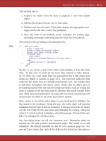
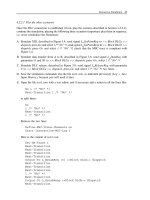
As expected, the generated MSC, represented in Figure 4.15, contains only process DLC
of block DLCa, and displays N320cnt plus the state of the process. You can see that the
number of retransmission of SABME is correct.
But now if you press on Transition, the Simulator answers: No process instance scheduled
for a transition. It means that the signal DLCstopped that you see at the bottom of the
MSC trace is not expected by the process dispatch: it goes into the input queue of process
dispatch in block DLCa, but unfortunately under the current state of dispatch there is no
input of signal DLCstopped.
J. Save the MSC: in the MSC Editor, select File > Save As, navigate to the desired directory,
enter retry1.msc and press OK.
K. Save the simulation commands into a file: in the Simulator, select Log > Save Input History,
select All files,enterretry1.com and press OK.
L. Open the file retry1.com with a text editor, and if necessary add a return before each 2 in
the Go line, to get the following file:
Set-GR-Trace 1
Set-MSC-Trace System V76test 0
Set-MSC-Trace Process <<Block DLCa>> DLC 2
List-MSC-Trace-Values
Start-Interactive-MSC-Log 2
Output-To L_EstabReq (0) <<Block DLCa>> dispatch
Go
2 /* "Yes" */
2 /* "Yes" */
2 /* "Yes" */
14
Conditional means that an entity – for example, a process – will be traced only if it exchanges signals with entities
present in the MSC trace. This avoids having entities present in the MSC trace but not exchanging any signal.
Interactive Simulation 53
DLC_1_1
process
<<Block DLCa>> DLC
Void_2
/* DLCstopped
never input. */
Void_2
waitUA
task
N320cnt := 3
waitUA
task
N320cnt := 2
waitUA
task
N320cnt := 1
waitUA
task
N320cnt := 0
MSC retry1
DLCstopped
(0)
T320(12.00)
V76frame ( SABME : (. 0 .) )
V76frame ( SABME : (. 0 .) )
V76frame ( SABME : (. 0 .) )
V76frame ( SABME : (. 0 .) )
T320(12.00)
T320(12.00)
T320(12.00)
Figure 4.15 The three SABME retransmissions in the MSC generated by the Simulator
2 /* "Yes" */
Next-Transition
Do not exit from the Simulator.
4.2.3.2 Analyze the bug
To understand the bug, you will search in which state process dispatch (in block DLCa)was
when process DLC transmitted the signal DLCstopped to it.
A. In the Simulator, select View > Command Window:theCommand Window appears, as
shown in Figure 4.7; check the box List-Process: you can see that dispatch in block DLCa
is in state waitUA.
B. In the Simulator, select Show > Prev Symbol: as shown in Figure 4.16, in process DLC the
Editor selects the stop symbol, below the output of DLCstopped, which caused the problem.
54 Validation of Communications Systems with SDL
Figure 4.16 Finding the stop symbol that caused the problem
C. In the SDL Editor, select Page > Edit Reference Page: the block type V76 DLC is now
displayed, as in Figure 3.12; you see that signal DLCstopped goes to process dispatch,
through the signal route DLCs.
D. In the SDL Editor, double-click on the process dispatch to open it; press the Next Page
button to display part2: you see that under state waitUA, the input of signal DLCstopped
is missing.
E. Exit from the Simulator.
4.2.3.3 Correct the bug
You will add the missing input of signal DLCstopped under state waitUA in process dispatch.
A. In Windows (or Unix), make a copy of the file dispatch.spr, containing the process dispatch,
into dispatch
v1.spr. Continue editing dispatch.spr.
B. In process dispatch, select the input of DLCstopped and the next three symbols under the
state ready, copy them, paste them near state waitUA and connect the state to the input as
shown in Figure 4.17.
Interactive Simulation 55
waitUA
V76frame
(V76para)
DLCstopped
(DLCnum)
V76para ! present
L_ReleaseInd
(DLCnum)
V76frame(V76para)
TO DLCs(V76para
! UA ! DLCi)
DLCs(DLCnum)
:= NULL
ready - ready
UA
ELSE
Figure 4.17 Missing DLCstopped input added under state waitUA
C. In the pasted transition, don’t forget to replace - in the nextstate symbol by ready,otherwise
you would be stuck in state waitUA.
D. Save the SDL model.
4.2.3.4 Simulate to check the bug correction
To check that the bug has been corrected, you will load and automatically replay the scenario
stored in Section 4.2.3.1.
A. In the Organizer, select the SDL system V76test and press the Simulate
button: Tau
compiles the SDL model and starts the Simulator.
B. Select Execute > Command Script, choose retry1.com and press OK: the Simulator executes
the commands contained in retry1.com.
This time, the bottom of the MSC generated by the Simulator looks like Figure 4.18(b):
signal DLCstopped has been consumed by process dispatch. The bug is corrected.
DLCstopped
(0)
DLCstopped
(0)
(a) (b)
Figure 4.18 Signal DLCstopped in the process queue (a) and consumed (b)
4.2.4 Detect nonsimulated parts
After a simulation session, the SDL Coverage Viewer displays the SDL symbol coverage
15
.
This shows you which parts of the SDL model have not been simulated.
15
A counter is associated with each SDL symbol: every time a symbol is simulated, its counter is incremented. A
value of 0 means never simulated.
56 Validation of Communications Systems with SDL
Then you can simulate the SDL model again until you reach 100% symbol coverage. After
playing all possible scenarios (which is easier using exhaustive simulation, if the model does
not have too many states), the symbols not simulated are considered as “dead” parts: they can
be removed, after careful inspection.
A. If the Simulator is already running, restart it and go to C.
B. In the Organizer, select the SDL system V76test and press the Simulate
button: Tau
compiles the SDL model and restarts the Simulator.
C. Select Execute > Command Script, choose test1.com and press OK: the Simulator executes
the commands contained in test1.com.
D. Select Show > Coverage: the SDL Coverage Viewer appears, as illustrated in Figure 4.19,
displaying the 21 SDL symbols that have never been executed since the Simulator startup.
21 symbols
not executed
36 executions of
symbols in DLC
proportional to model
coverage (82%)
proportional to
executions of
symbols (138)
package V76
system V76_DLC
Figure 4.19 The SDL Coverage Viewer
E. In the Coverage Viewer, double-click the first symbol below DLC (an input): the SDL Editor
opens the process DLC and selects the uncovered symbol, as depicted in Figure 4.20.
F. In the Coverage Viewer, select the top symbol above total and press the Details button: the
SDL coverage details window appears, as shown in Figure 4.21. There you see that:
Interactive Simulation 57
Figure 4.20 A symbol not simulated automatically located
73 symbols have
been executed 1 time
Figure 4.21 The SDL coverage details
• 73 symbols have been executed 1 time,
• the total symbols coverage for the SDL model is 82%,
• 21 symbols, displayed at the bottom of Figure 4.19, have not been executed
G. Close the coverage details window.
58 Validation of Communications Systems with SDL
2 transitions
not executed
Figure 4.22 The SDL Coverage Viewer in transition tree mode
H. In the Coverage Viewer, press the Tree Mode button: the SDL Coverage Viewer switches
from symbol to transition coverage tree, as shown in Figure 4.22.
The information displayed here is more synthetic as it only shows the transitions not executed.
But even if it indicates that all the transitions have been executed, a branch after an answer to
a decision could remain uncovered: this can only be detected by the symbol coverage tree.
As we have only replayed the scenario test1.scn, it is normal that two transitions that are
not executed are displayed in Figure 4.22, one in process dispatch corresponding to the input
of DLCstopped, the other in process DLC corresponding to the input of timer T320;tosim-
ulate them, we also need to replay retry1.com, and then press on Transition to execute one
more transition.
4.2.5 Validate against more scenarios
After simulation of the main scenarios, described in Section 4.3.2, it is wise to play more
scenarios to check the reaction of the SDL model. Those scenarios can be
Interactive Simulation 59
• more complex: for example, two simultaneous connections,
• beyond limits: for example, creation of more connections than allowed.
4.2.5.1 Simulate two simultaneous connections
You will simulate to check that the SDL model c an handle two connections in parallel.
A. In the Simulator, select File > Restart and press OK.
B. Type the command Define-MSC-Trace-Channels on (or type d-m-t-c on)togettwoenvi-
ronment instances.
C. Select Trace > MSC Trace: Start: a Select window appears. In the Select window, select
0/*BasicMSC ∗/ and press OK.
D. Select Execute > Command Script, choose cnx1.com and press OK; the Simulator executes
the commands contained in cnx1.com: one instance of process DLC exists on each side of
the system.
Now establish one more connection:
E. Press the Send To button: select L
EstabReq and press OK. Enter the value 1 for the parameter
of signal L
EstabReq and press OK. Select the target process << Block DLCa >> dispatch
and press OK.
F. Press several times the Transition button until you see the Select – Enter path window. A
new instance of process DLC is created.
G. In the Select - Enter path window, select 1/*
No
*/ and press OK.
H. Press ONCE ONLY the Transition button.
I. Press the Send To button: select L
EstabResp and press OK, select the target process
<< Block DLCb >> dispatch and press OK.
J. Press several times the Transition button until you see the Select – Enter path window.
K. In the Select - Enter path window, select 1/*
No
*/ and press OK.
L. Press two times the Transition button: signal L
EstabConf is transmitted.
The new connection has been established between sides A and B.
M. To check the state of the two instances of process DLC on each side, select View >
Command Window; in the List-Process part, you see that all four instances of process DLC
exist and are in state connected:
DLC:2 connected
<<Block DLCa>>
DLC:1 connected
<<Block DLCa>>
DLC:2 connected
<<Block DLCb>>
DLC:1 connected
<<Block DLCb>>
60 Validation of Communications Systems with SDL
N. To test that the new connection
16
works, let us transfer data through it: send signal
L
DataReq with parameters 1 and 39 to << Block DLCa >> dispatch,pressGo,select
1/*
No
*/ and press Go.
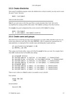
The generated MSC, represented at blocks level by Figure 4.23, shows that block DLCb
transmitted signal L
DataInd(1, 39) to env b (representing Service User B): the data 39
has been successfully transferred from A to B through DLC 1.
DLCb_3
block
DLCb
DLCa_2
block
DLCa
dataLink_1
block
dataLink
DLCaSU
Transfer of data
39 through DLC
number 1:
DLC number
1
established.
DLC number 0
established
.
MSC cnx2
V76frame
( I : (. 1, 39, 15 .))
V76frame
( I : (. 1, 39, 15 .))
L_DataInd
( 1, 39)
L_DataReq
( 1, 39)
V76frame
( UA : (. 1 .) )
V76frame
( UA : (. 1 .) )
V76frame
( SABME : (. 1 .))
L_EstabInd
(1)
L_EstabResp
L_EstabConf
(1 )
V76frame
(SABME : (. 1 .) )
L_EstabReq
(1)
L_EstabConf
(0 )
L_EstabReq
(0)
L_EstabResp
L_EstabInd
(0)
V76frame
(SABME : (. 0 .))
V76frame
( UA : (. 0 .) )
V76frame
(SABME : (. 0 .))
V76frame
( UA : (. 0 .))
DLCbSU
Figure 4.23 Two DLCs 0 and 1 connected in parallel
O. Save the simulation commands into a file: in the Simulator, select Log > Save Input History,
select All files,entercnx2.com and press OK.
P. Open the file cnx2.com with a text editor, and if necessary add a return in the two lines:
Next-Transition 1 /* "No" */
16
The DLC number (of type DLCident) of the new connection is 1, and the corresponding instance number of process
DLC (given by the Simulator) is 2.
Interactive Simulation 61
to get:
Next-Transition
1 /* "No" */
Add a return in the line containing Go if necessary.
Transform the absolute file names into relative file names (remove pathnames such as C:\
etc. before
cnx1.com).
Remove the following line, redundant with
Include-File cnx1.com:
execute-command-script cnx1.com
The file cnx2.com should now contain:
Define-MSC-Trace-Channels on
Start-Interactive-MSC-Log 0 /* Basic MSC */
Include-File cnx1.com
Output-To L_EstabReq (1) <<Block DLCa>> dispatch
Next-Transition
Next-Transition
Next-Transition
1 /* "No" */
Next-Transition
Output-To L_EstabResp <<Block DLCb>> dispatch
Next-Transition
Next-Transition
Next-Transition
1 /* "No" */
Next-Transition
Next-Transition
Output-To L_DataReq (1, 39) <<Block DLCa>> dispatch
Go
1 /* "No" */
Q. Save the MSC: in the MSC Editor, select File > Save As,entercnx2.msc and press OK.
4.2.5.2 Simulate an attempt to create too many connections
You w ill simulate to see what happens if you try to create more connections than allowed. The
maximum number of parallel connections in our model is maxDLC + 1 = 2. Figure 3.12 shows
that this number corresponds to the maximum number of instances of process DLC, identical
to the size of the array DLCs, declared in Figure 3.14.
A. If you exited from the Simulator since Section 4.2.5.1, launch the Simulator and replay the
command script cnx2.com: two instances of process DLC exist on each side of the system,
the maximum is reached.
B. Press the Send To button: select L
EstabReq and press OK, enter the value 0 for the
parameter of signal L
EstabReq and press OK.
62 Validation of Communications Systems with SDL
C. Select the target process << Block DLCa >> dispatch and press OK.
D. Press the Transition button: you see in the MSC trace that the system answers with an
L
RelelaseInd(0): it means that no more connections can be established.
But if you look at the Command Window, you discover that process dispatch in block
DLCa is stuck in state waitUA: this is a modeling bug.
E. Exit from the Simulator.
You will correct process dispatch to remain in state ready instead of going to state waitUA
after transmitting L
RelelaseInd:
F. In Windows (or Unix), make a copy of the file dispatch.spr into dispatch
v2.spr
G. In process dispatch,pagepart2, select the output of L
RelelaseInd under the ELSE branch
of the decision and double-click on the state palette symbol; enter – in the newly created
symbol, as shown in Figure 4.24.
PROCESS dispatch(1, 1) part2(2)
L_EstabReq
(DLCnum)
DLCs
(DLCnum)
DLCnum not
used, we create
an instance of
process DLC
DLC
(DLCnum, True)
L_ReleaseInd
(DLCnum)
DLCs(DLCnum)
:= OFFSPRING
We store into the
table the PID of
the new instance
-
waitUA
NULL
ELSE
Figure 4.24 After the bug correction with the SDL Editor
H. Save the process.
I. Simulate again to check that the bug has disappeared: launch the Simulator, replay the
command script cnx2.com as before, send an L
EstabReq to the model and execute its
input: you see that process dispatch now stays in state ready.
4.2.6 Write a script for automatic validation
In an actual project, to test a more complex SDL model, you would produce, for example,
40 simulation scripts. After a change in the SDL model, you must check that it still works
correctly (nonregression) : the Simulator command language
17
enables you to write a script to
17
A few commands such as add-macro are interpreted by the SimUI (Simulator User Interface), not by the Simulator
itself.
Interactive Simulation 63
automatically replay the 40 scripts (stored in .comfiles) and write the test results into a log
file, and write the MSC trace. After the execution of the script, looking into the log file and
into the MSC trace tells you if the 40 scripts have been replayed correctly or not.
Here is a Simulator script to replay our two scripts test1.com and cnx2.com:
Log-On test_res1.wri
Define-MSC-Trace-Channels on
Start-Interactive-MSC-Log 0 /* Basic MSC */
Include-File test1.com
/* The two arrays DLCs must contain (: null, null :): */
Examine-Variable ( <<Block DLCa>> dispatch DLCs
Examine-Variable ( <<Block DLCb>> dispatch DLCs
Include-File cnx2.com
List-Process - /* to check that all DLC inst. are connected */
Log-Off
Here are a few more explanations on the script:
•
Log-On test res1.wri: all simulation traces will be written into the file test res1.wri.
•
Define-MSC-Trace-Channels on: to get two environment instances in the MSC trace.
•
Start-Interactive-MSC-Log 0: starts the MSC trace (0 means MSC without states
or actions).
•
Include-File test1.com: executes the commands contained in the file test1.com.
•
Include-File cnx2.com: executes the commands contained in the file cnx2.com.
•
Log-Off: stops the logging, otherwise the file cannot be opened while the Simulator
is running.
Once you have typed the script into the file script1.com, execute it:
A. Launch the Simulator.
B. Select Execute > Command Script, choose script1.com and press OK: the Simulator exe-
cutes the commands contained in script 1.com. If the model (and the script!) is correct, you
get a file test
res1.wri containing the simulation traces, plus an MSC displayed by the MSC
Editor
18
.
You will learn in Chapter 5 how to check that your SDL model behavior complies with an
MSC, for example. It will be even more powerful to test an SDL model automatically: for
example, we will be able to check the value of a parameter in a signal transmitted.
4.2.7 Other Simulator features
This section describes features of the Simulator that are not absolutely essential to validate an
SDL model, but which can be very helpful and save a lot of time on an actual system validation.
18
To speed up the replay for a large number of long scenarios, you can turn off the SDL trace.
64 Validation of Communications Systems with SDL
4.2.7.1 Macros
You can define macros (a kind of aliases), for example, to give your own name to a Simulator
command. To define the macro trans:
Command: add-macro trans Next-Transition
To list the current defined macros:
Command: list-macros
Number of macros defined: 1
Macro name: trans
Macro value: Next-Transition
Then, you have only to enter $trans instead of Next-Transition (or n-t):
Command: $trans
Next-Transition
*** TRANSITION START
* PId : AtoB:1
* State : start state
* Now : 0.0000
*** NEXTSTATE ready
4.2.7.2 Automatic script execution at Simulator startup
When the Simulator starts, the file siminit.com, if present in the current directory, is automati-
cally executed, as shown in Figure 4.25. For example, siminit.com could contain the following
commands to automatically start the MSC and SDL traces:
Start-Interactive-MSC-Log 0
Set-GR-Trace 1
siminit.com
SDL
Simulator
Figure 4.25 The Simulator startup file
4.2.7.3 Running the Simulator without its graphical interface
To perform automatic tasks such as automatic replay of scenarios, the Simulator can be launched
without its graphical interface; this is called batch mode. To run in batch mode, after the build,
type the following command (we suppose the SDL model is in the file v76.pr) in a DOS shell
(containing V76test
smc.exe) or in a Unix shell:
F:\DONNEES\V76>V76test_smc.exe
No connection with the Postmaster. Running stand-alone.
Interactive Simulation 65
Welcome to the SDL SIMULATOR. Simulating system V76test.
Command :
To see the Ready Queue, enter List-Ready-Queue,orl-r-q: the Simulator displays the list of
processes ready to execute a transition:
Command : l-r-q
Entry PId State Signals Signal instance
1 AtoB:1 start state 0 -
2 BtoA:1 start state 0 -
3 dispatch:1 start state 0 -
<<Block DLCa>>
4 dispatch:1 start state 0 -
<<Block DLCb>>
To execute a transition, enter Next-Transition or n-t:
Command : n-t
*** TRANSITION START
* PId : AtoB:1
* State : start state
* Now : 0.0000
*** NEXTSTATE ready
Then you can enter any Simulator textual command:
Command : Output-To L_EstabReq(0) <<Block DLCa>> dispatch
Signal L_EstabReq was sent to <<Block DLCa>> dispatch:1 from env:1
Process scope : <<Block DLCa>> dispatch:1
The commands to execute can be inserted in the file siminit.com, automatically played when
the Simulator starts. For example, the automatic simulation script script1.com described in
Section 4.2.6 can be executed automatically if the file siminit.com contains:
Include-File script1.com
quit
4.2.7.4 Commands history
The Simulator automatically stores the last 100 commands executed. To reenter a Simulator
command, simply scroll by pressing the up arrow key until you see the desired command.
4.2.7.5 Examining the SDL model: the Command window
Select View > Command Window:theCommand Window appears, as shown in Figure 4.26.
The upper part of the Command Window displays the ready queue of the Simulator: the
next process instance to be executed is the first process in the ready queue (entry number 1),
66 Validation of Communications Systems with SDL
Figure 4.26 The Command Window
here instance 1 of process dispatch in block DLCa. This instance is in state ready and has one
signal in its queue, L
EstabReq.
The lower part of the Command Window displays, for each process instance,
• its current state,
• the number of signals in its input queue,
• the name of the first signal in its input queue.
4.2.7.6 Examining the SDL model: Examine-Variable
The Examine-Variable command displays the contents of any SDL variable. The Simulator pro-
vides a button Variable in the Examine group to avoid entering the textual command manually.
To examine variable DLCs in process dispatch in block DLCa, press the button Variable,
select << Block DLCa >> dispatch and select DLCs; the Simulator displays the equivalent
textual command followed by its result:
Command : Examine-Variable ( <<Block DLCa>> dispatch DLCs
DLCs (DLCsArray) = (: <<Block DLCa>> DLC:1, null :)
The result indicates that DLCs is of type DLCsArray and that the first element of the array
contains the Pid of the first instance of process DLC in block DLCa, the second element
containing Null.
Interactive Simulation 67
4.2.7.7 Examining the SDL model: List-Input-Port
To display the input queue contents of process dispatch in block DLCb, select Examine >
Set Scope to set the scope to the desired process:
Command : Set-Scope <<Block DLCb>> dispatch
Process scope : <<Block DLCb>> dispatch:1
then select Examine > Input Port:
Command : List-Input-Port
Input port of <<Block DLCb>> dispatch:1
Entry Signal name Sender
*1 L_DataReq env:1
2 L_EstabResp env:1
The queue contains two signals, L DataReq and L EstabResp. To display the parameters of
signal L
DataReq, select Examine > Signal and enter the entry number (here 1):
Command : Examine-Signal-Instance 1
Signal name : L_DataReq
Parameter(s) : 0, 97
4.2.7.8 Examining the SDL model: the watch window
The Edit > Watch Window command opens a watch window displaying the contents of any
SDL variable, refreshed every time its value changes.
In the Watch window, select Watch > Add and enter the name of the SDL variable to
watch. For example, to watch variable N320cnt in process DLC in block DLCa, type the syntax:
( <<Block DLCa>> DLC N320cnt
The easiest way to get the correct syntax is to examine the variable by pressing the Vari-
able buttonintheExamine group; then you can copy the argument of the Examine-Variable
command and paste it into the Add Watch field.
To avoid entering the variable names again, the next time you launch the Simulator, you
can select File > Save As in the watch and enter the file name def.vars. The Simulator will
automatically load the variable names into the watch window as shown in Figure 4.27.
Figure 4.27 The Simulator watch window
68 Validation of Communications Systems with SDL
4.2.7.9 Modifying the SDL model: Rearrange-Ready-Queue
To test a special case impossible to simulate with the current Simulator process scheduling, you
may want to rearrange the Simulator ready queue. To do that, select Change > Ready Queue
and enter successively the queue entry numbers to swap. Here is an example where we have
swapped entries 3 and 2:
Command : List-Ready-Queue
Entry PId State Signals Signal
instance
1 AtoB:1 start state 0 -
2 BtoA:1 start state 0 -
3 dispatch:1 start state 0 -
<<Block DLCb>>
Command : Rearrange-Ready-Queue 3 2
Rearranged!
Process scope : AtoB:1
Command : List-Ready-Queue
Entry PId State Signals Signal
instance
1 AtoB:1 start state 0 -
2 dispatch:1 start state 0 -
<<Block DLCb>>
3 BtoA:1 start state 0 -
Then process dispatch will be executed immediately after process AtoB.
4.2.7.10 Modifying the SDL model: variables
To change the value of a variable, you must first set the scope to the desired process instance,
if it is not in the current scope.
For example, to enter 2 into the variable N320cnt in block DLCa,useExamine > Set Scope
and select << Block DLCa >> DLC . Then select Change > Variable, choose N320cnt and
enter 2.
Command : Set-Scope <<Block DLCa>> DLC
Process scope : <<Block DLCa>> DLC:1
Command : Assign-Value N320cnt 2
Value assigned
N320cnt (integer) = 2
To change easily the values of complex structures such as arrays, struct or ASN.1 values,
the Simulator automatically prompts you for each required field value.
4.3 CASE STUDY WITH OBJECTGEODE
The tools and platform used for the exercises are described in Section 1.5. The V.76 SDL
model used for this case study is presented in Chapter 3.
Interactive Simulation 69
4.3.1 Prepare the Simulator
4.3.1.1 Compile the SDL model
A. Download from the Internet (see the ftp address in Section 1.5) or create the SDL V.76
model, and launch the ObjectGeode SDL Editor: double-click the icon v76.pr
19
,orforUnix
type geodedit v76&.
B. In the SDL Editor, select Tools > SDL & MSC Simulator. The window represented in
Figure 4.28 appears.
Build
Figure 4.28 The ObjectGeode Launcher
The left area
20
contains v76.pr, the name of the file containing the SDL model. Remember
to save your SDL model each time you modify it in the Editor, otherwise the file v76.pr
will not contain your changes.
C. Select File > Save to create the file v76.ogl
21
in your current directory (this feature may
not be available in the Unix version).
D. Press the Build button: this checks your SDL model, and if it is correct translates it into C
code
22
, stored in the subdirectory .geodesm. Then the C files are compiled
23
and linked to
the simulator library, to produce the executable file v76.sim , as depicted in Figure 4.29.
4.3.1.2 Start the Simulator
A. Press the Execute button indicated in Figure 4.30 to start the Simulator. The Simula-
tor
24
main window appears, as shown in Figure 4.31. Drag it to the upper left corner
of your screen.
19
We recommend setting your Windows options to display the file extensions (in Windows NT4, open Workstation,
then select Display > Options:intheDisplay tab, check Display all files and uncheck Mask the extensions for known
file types,thenpressOK ).
20
If this area contains other models you do not want to simulate, remove them: select them and do Edit > Remove.
By default, the files you see in this area are all the files loaded in the SDL Editor when you invoked the command
Tools > SDL & MSC Simulator, MSCs included.
21
This file saves the current simulation builder options and SDL file name, and enables launching the simulator (or
the Target C Code Generator) without the SDL Editor.
22
The code generated here is specific to simulation. Another code optimized for real-time targets is generated when
using the tool ObjectGeode SDL C Code Generator.
23
If you do not see the file names b0.c and so on, as in Figure 4.30, check that a C compiler is available.
24
In fact when you start the Simulator, two processes start: ogsmgui.exe, the Graphical User Interface, and v76.sim,
the command line interface Simulator.
70 Validation of Communications Systems with SDL
SDL
model
v76.pr
C
compiler
& linker
C
code
v76.sym
Simulation
builder
gsmcomp
SDL
Simulator
GUI
v76.sim
simul. library
Figure 4.29 The ObjectGeode simulation building
Execute
Figure 4.30 The Simulator is ready to be launched
4 transitions ready
Figure 4.31 The Simulator main window
Interactive Simulation 71
Four transitions can be fired, because the V.76 model contains four process instances: AtoB(1)
25
,
instance number one of process AtoB, BtoA(1), DLCa!dispatch and DLCb!dispatch.
4.3.1.3 Start the SDL tracking
A. Press the button SDL tracking shown in Figure 4.31: this opens a window in the SDL
Editor, named Default tracking. Close (do not minimize) the other SDL windows in the
Editor, if any.
B. Select the first ready transition in the list shown in Figure 4.31: the SDL Editor opens
process AtoB(1) and displays in bold its start symbol, as shown in Figure 4.32(a).
process type toPeer
gIn
V76frame
ready
ready
V76frame(V76par)
etc.
process type toPeer
gIn
V76frame
ready
ready
V76frame(V76par)
ready
etc.
(a) (b)
Figure 4.32 SDL tracking: start transition ready (a) and executed (b)
C. Double-click
26
on the same transition (atob(1):start): this executes the transition from the
start symbol to the state ready which is now in bold, as depicted in Figure 4.32(a).
D. Double-click on the three transitions remaining in the list to execute them. As you can see
in Figure 4.33, no transition is ready to be fired: this is a deadlock. In fact, the simulation
is blocked because the SDL model now expects to receive some external signals.
E. Save the current simulation scenario into the file start.scn by typing the following command
in the Simulator:
save start.scn
4.3.1.4 Send signals to the model
Figures 4.34 and 4.35 show that the V.76 SDL model requires the input of external sig-
nals, such as L
EstabReq, contained in the signallist su2dlc on the channels DLCaSU and
DLCbSU. We will tell the Simulator to send such signals to the SDL model, using the feed
command
27
.
25
The Simulation Builder converts the SDL names to lower case; thus the actual names you see in the tool do not
contain capitals.
26
If your mouse has three buttons, it is easier to click once on its middle button.
27
The Simulator output command (in the Execute menu) can also be used, but it is less convenient as it sends the
signal only once: to send the signal again, the output command must be repeated, which is not possible during an
automatic simulation (such as random or exhaustive).
72 Validation of Communications Systems with SDL
Figure 4.33 The simulation is blocked
system V76test
USE V76;
/* Simplified V76 model. */
DLCaSU
(su2dlc)
(dlc2su)
DLCaDL
V76frame
V76frame
DLCbDL
V76frame
V76frame
DLCbSU
(su2dlc)
(dlc2su)
dataLink
DLCa : V76_DLC
SU
DL
DLCb : V76_DLC
SU
DL
L_EstabReq etc.
Figure 4.34 The V.76 model waits for external signals
process dispatch(1, 1)
ready
L_DataReq
(DLCnum, uData)
L_ReleaseReq
(DLCnum)
L_EstabReq
(DLCnum)
Figure 4.35 Some of the external signals required in the blocks DLCa and DLCb
Interactive Simulation 73
1
2
3
Figure 4.36 Adding feed commands
A. In the Simulator, select Edit > Feed: the window shown in Figure 4.36 appears. Select a
channel (1), a signal (2), enter the value of the parameter(s) (3) and press on Add: you have
created one feed.
This means that every time the process dispatch in the block DLCa is in a state where the
input of L
EstabReq is possible (i.e. input queue empty and state = ready, see Figure 4.35),
the Simulator will propose to execute the input of L
EstabReq by dispatch
28
.
B. Continue in the same way to create the following feed list, then press on Close.
dlcasu l_estabreq(0)
dlcasu l_estabreq(1)
dlcasu l_setparmreq()
dlcasu l_releasereq(1)
dlcasu l_datareq(0,86)
dlcasu l_datareq(1,39)
dlcbsu l_estabresp()
28
As opposed to actual signal outputs, signals sent by Simulator feed commands do NOT go into the input queue of
the target process (here dispatch). The behavior is equivalent, but not using the queue reduces the number of global
states during exhaustive simulation.