Validation of Communications Systems with SDL phần 7 ppt
Bạn đang xem bản rút gọn của tài liệu. Xem và tải ngay bản đầy đủ của tài liệu tại đây (266.88 KB, 28 trang )
Random Simulation 173
Figure 6.5 Adding the stop condition
6.3.1.2 Analyze the error
To understand the bug, you will search in which state process dispatch was (in block dlcb)
when process DLC transmitted to it the signal dlcstopped.
A. In the Simulator, press the button Watch and select States: a watch appears, shown in
Figure 6.6, displaying the state of each process instance. You see that process dispatch in
block dlcb is in state waitparmresp.
Figure 6.6 The watch window
B. In the Editor, open the partition part1 of process dispatch: you see that in state waitparm-
resp, the only input is L
SetParmResp; therefore, when a v76frame is first in the process
queue, it is discarded.
If required, the MSC trace corresponding to the bug can be generated by pressing the buttons
Start MSC, undo
and then redo .
We will not correct this bug, because we will learn how to find it with exhaustive simulation.
174 Validation of Communications Systems with SDL
6.3.2 Multiple random simulations
The random simulation algorithm used in the Simulator is based on a pseudorandom number
called seed. The initial default seed value (619430284 in the version used) can be changed
using Edit > Configuration. At each random simulation step, the Simulator:
• executes a transition selected among the firable transitions according to the current seed
value, (for example, if there are two firable transitions, depending on the seed value, the first
or the second transition is executed),
• computes the new seed value function of the current seed value.
It means that the seed changes at every simulation step. Also, if you go back (undo or init
commands) to previous simulation steps, seed does not return to its previous value: this is to
simulate different branches easily. Otherwise, using the same seed from the same model’s state
would simulate the same scenario.
To illustrate this:
A. Quit the Simulator, start the Simulator as indicated in Section 6.3.1.1 and enter the stop
condition rstep = 500 .
B. Press on
to start the random simulation: at Step 261 (you may get another number), the
simulation stops (unexpected signal).
C. Press on init
, four times on redo and then on : this time, the simulation stops at
Step 264 (you may get another number).
D. Repeat the same sequence: this time, the simulation stops at Step 48 (you may get
another number).
The fact that the random simulation starting from the same SDL model state stops at
Step 261, 264 or 48 means that different scenarios have been simulated, because the seed
was always different (computed at every step, then never reinitialized during init).
To automatically perform the previous random simulations, we are going to write a script.
E. With a text editor, type the following lines and save the file as rand.wri:
init return to step 0
source start.scn execute the 4 start
untrace all remove textual traces
define trace_stmt ’false’ remove PR traces
Protection against double declaration of sim_ok:
if ’$vars_declared’ = ’’
define vars_declared ’Yes’
dcl sim_ok Boolean
fi
let sim_ok = true
while sim_ok
Random Simulation 175
print seed
go until step = 500 random simulation
if step /= 500
let sim_ok = false
fi
print step
init
redo 4 play again the 4 starts
endwhile
F. In the Simulator, select Edit > Configuration and uncheck the box Trap unexpected signals;
otherwise our script would stop during the first iteration.
G. In the Simulator, type the command:
source rand.wri
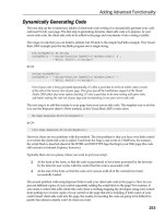
The Simulator performs four times the while loop (you may get different results), as shown in
Figure 6.7: three times without discovering any error before Step 500, then one more iteration
where an error is encountered at Step 60.
The error encountered is: No receiver for output l
releasereq from dlcb!dispatch via dlcs to
dlcb!dlc(1). It means that instance 1 of process DLC in block DLCb was stopped before the
signal L
ReleaseReq was transmitted to it by process dispatch.
As performed previously, you could press the Traces: Defaults button to turn the trace on (it
was removed by the script to speed up the simulation), and use the undo command to get the
MSC trace to understand the error and fix it.
If you launch again the script rand.wri without exiting from the Simulator, the seed values
will be different, and the number of while loops performed will change. If the simulation never
terminates (no error is encountered), you can stop it by pressing the halt
button.
To see the states, transitions and basic blocks coverage obtained by the script execution, you
could type, respectively:
print state_cover_rate(system)
print trans_cover_rate(system)
print bb_cover_rate(system)
The Simulator answers the following percentages:
state_cover_rate(v76test) = 100.00
trans_cover_rate(v76test) = 93.10
bb_cover_rate(v76test) = 89.28
More details on coverage can be found in the Hierarchy Browser (View > Hierarchy).
6.3.3 Random simulation with observers
You will run the random simulation on the V.76 SDL model monitored by an observer MSC,
to automatically check that the simulated behavior complies with the expected behavior.
176 Validation of Communications Systems with SDL
initial seed
end of first go
init (back to step 0)
redo 4
next seed
end of second go
init (back to step 0)
end of third go
init (back to step 0)
fourth go: bug at step 60
Figure 6.7 The simulation trace of the script rand.wri
6.3.3.1 Random simulation not guided
A. Quit the Simulator and the ObjectGeode Launcher.
B. With a text editor, open the file v76.startup and add the comment delimiter
asbelowto
prevent the feed commands execution (because when an MSC is compiled with the SDL
model, feeds are automatically created, making duplicates):
source v76_feed.wri
Random Simulation 177
C. In the SDL Editor, unload all files except v76.pr, and load the file test1.msc.
D. Select Tools > SDL & MSC Simulator.
E. In the ObjectGeode Launcher, remove any file other than v76.pr and test1.msc ,pressthe
Build button, then, if you do not get any errors, press the Execute button. The Simula-
tor starts.
F. In the Simulator enter the stop condition rstep = 1000.
G. Press the button Traces: Off to speed up the simulation.
H. Press on
to start the random simulation: at Step 46 (you may get a different number),
the simulation stops (unexpected signal).
I. Press on init
, four times on redo (to skip the start transitions) and then on the
go
button: this time, the simulation stops at Step 59 (no receiver for output).
J. Repeat the same sequence several times: the simulation stops, respectively, at Steps 41, 56,
46, 69 and 319 (you may get different numbers).
K. You could continue the sequence init; redo 4; go many times, without reaching the observer
MSC’s success state.
If you look at the MSC test1, this is normal: the probability to randomly simulate the
successful connection, followed by an XID, then a data transfer and finally a connection release
are extremely low.
In our V.76 SDL model, there are several possible cascading simulation choices, as in a
complex maze. Let’s count the probability to verify the MSC:
• Step 4: choice between sending L
DataReq, L EstabReq, L SetparmReq or L ReleaseReq
to the SDL model; therefore, four possibilities,
• Step 5: choice between sending L
ReleaseReq or starting DLC process instance,
• Step 6: choice between sending L ReleaseReq, timer T320 or input of v76frame,
• etc.
If we multiply all the number of possibilities offered at each step, we get:
• 4 × 2 × 3 × 2 × 3 × 2 × 3 × 3 × 2 × 3 × 5 = 77 760 to establish the connection (reception
of L
EstabConf ),
• followedby4× 4 × 2 × 5 × 4 × 5 × 2 × 5 = 32 000 for the XID exchange,
• followedby4× 4 × 4 × 2 × 5 = 640 for the data transfer,
• followedby4× 4 × 5 × 2 × 5 × 4 × 5 × 2 × 6 × 4 × 3 × 4 = 9 216 000 for the connec-
tion release.
Therefore, the probability to simulate the expected behavior test1 in this configuration can
be estimated at: 1/77 760 × 32 000 × 640 × 9 216 000 = 1/14.677.000.000.000.000.000.
178 Validation of Communications Systems with SDL
As certain choices are equivalent, the probability is not so low, but certainly too small to
verify the MSC, even performing years of random simulation.
This is why we must guide the simulation to reduce the number of possibilities at each
simulation step, as explained in the next section.
6.3.3.2 MSC-driven random simulation
In a way similar to Tau SDL Suite Validator, we will perform a simulation guided by the MSC
test1.
A. Quit the Simulator and the ObjectGeode Launcher.
B. With a text editor, check that the file v76.startup contains a c omment delimiter
asbelow
in front of the feed source line:
source v76_feed.wri
C. In the SDL Editor, check that the only files loaded are v76.pr and test1.msc.
D. In the SDL Editor, select the MSC test1 and choose Edit > MSC Simulation Properties:in
the Goal part, select the option Verify.PressOK and save the MSC.
E. Select Tools > SDL & MSC Simulator.
F. In the ObjectGeode Launcher, remove any file other than v76.pr and test1.msc,pressthe
Build button, then press the Execute button.
G. Check that the current simulation step is 4 (otherwise your startup file has not been executed).
If not, execute the 4 start transitions.
H. Press the button Traces: Off.
I. Press the button MSC-driven: Activate: this adds the filter condition filter error(observation),
which removes the transitions leading to a violation of the observer MSC.
J. Choose Edit > Configuration, select the box Reasonable environment and deselect the box
Loose time progression.
K. Select Edit > Filter Conditions and add successively:
trans atob(1) : decision_lose_the_frame(’Yes’)
trans btoa(1) : decision_lose_the_frame(’Yes’)
This prevents the Simulator from losing the frame in block dataLink.
L. Press on
to start the random simulation: at Step 12 (you may get a different number),
the simulation stops (deadlock).
M. Press on init
, press four times on redo (to skip the start) and then on : the simulation
stops at Step 41, indicating success(test1). It means that this time, the Simulator has selected
the correct transitions, simulating the behavior expected by the MSC test1.
If you simulate manually with the same Simulator settings (filter etc.), you will see that
most of the time there is only one transition to fire; therefore the probability to randomly play
Random Simulation 179
the expected scenario is high. If you remove filter error(observation), the success is extremely
difficult to obtain randomly.
6.3.4 Details on random simulation
6.3.4.1 Testing the simulator randomness
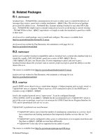
To know exactly the repartition of random choices performed by the Simulator, we have sim-
ulated the model shown in Figure 6.8. Each spontaneous transition increments a variable, to
count the number of time it is executed by the Simulator.
After executing the first transition (start), the Simulator, as expected, proposes five firable
transitions, as illustrated in Figure 6.9.
Then we remove the traces to speed up the simulation and enter the following command to
run 1000 random simulation steps:
go until rstep = 1000
process proc1
DCL
n1,
n2,
n3,
n4,
n5 Integer:= 0;
st1
st1
NONE
n1:= n1 + 1
-
NONE
n2:= n2 + 1
-
NONE
n3:= n3 + 1
-
NONE
n4:= n4 + 1
-
NONE
n5:= n5 + 1
-
system syst1
block1
block block1
proc1
Figure 6.8 SDL model to test random choices
Figure 6.9 The five firable transitions
180 Validation of Communications Systems with SDL
After the 1000 steps, the following results are obtained:
> print n1
proc1(1) ! n1 = 131
> print n2
proc1(1) ! n2 = 240
> print n3
proc1(1) ! n3 = 244
> print n4
proc1(1) ! n4 = 256
> print n5
proc1(1) ! n5 = 129
It shows that the random function used by the Simulator is not perfect as the first and last
transitions have been executed half as frequently as the others.
6.3.4.2 Running very long random simulations
During simulation (except in exhaustive modes), the following information is stored:
• the scenario, to be able to go back to any step using undo: one line per transition executed,
• the textual traces: several lines per transition executed, stored into the file model
name.log
and stored into the Simulator window in order to scroll up.
If you plan to run a very long random simulation (many million steps), you can select
Edit > Configuration and uncheck the box Scenario recording. However, in such case, no undo
or redo is possible. Concerning the textual traces, it is wise to turn them off; otherwise the log
file will be huge and many lines will be stored in the window.
6.4 ERRORS DETECTABLE BY RANDOM SIMULATION
The errors that random simulation can detect are the same as those that are detectable by
interactive simulation. The only difference is that random simulation runs automatically and
reports the error.
7
Exhaustive Simulation
In this chapter, after a presentation of the exhaustive simulation algorithms and of the two sim-
ple examples, you will learn how to validate the V.76 SDL model using exhaustive simulation:
automatically detecting bugs in a few seconds, detecting nonsimulated symbols, exploring mil-
lions of states in a few minutes, and using observers (stop conditions, rules, MSCs, processes or
GOAL). Then more simulation algorithms are described (supertrace, liveness etc.), and a strat-
egy is given to simulate SDL models with infinite or very large states graphs. Finally, the list of
errors that can be detected by exhaustive simulation is presented, for the two Simulators used.
7.1 INTRODUCTION
This chapter concerns exhaustive simulation, where all the reachable states of an SDL model
are computed, and also nonexhaustive algorithms such as bit-state, where some of the reachable
states can remain unexplored. The reader easily understands that computing all the reachable
states of an SDL model is not always possible, especially using exhaustive algorithms, because
exhaustive simulation needs to store the global states of the model (or at least their hash-code)
in RAM memory. The SDL model and the simulator must be tuned, to limit the memory used.
For example, more priority can be given to internal SDL events.
When I was using exhaustive simulation on a Unix server around 1993, equipped with
256 MB of memory (RAM), some people did not believe that such a huge memory could exist.
At the time of writing this book, 256 MB of memory on a PC cost only 30 euros or US$30:
anybody can run exhaustive simulation on a cheap PC!
Exhaustive simulation in systems engineering can be compared to ultrasound scan in medicine:
it reveals exactly what is inside a system, finding harmful behaviors early that would otherwise
be detected too late. Exhaustive simulation can find security failures in network software and
protocols before they are discovered and used by hackers to attack a system: for example, a
simplified model of a PC connected to the Internet could reveal dangerous scenarios that could
be fixed during the software design, instead of after several intrusions or virus attacks after
product delivery.
7.1.1 Exhaustive simulation
The aim of exhaustive simulation is not only to execute all the SDL symbols at least once
(static coverage) but also to execute all the behaviors of an SDL model (dynamic coverage):
that means executing all the SDL transitions from all the global states. The global states are also
Validation of Communications Systems with SDL: The Art of SDL Simulation and Reachability Analysis.
Laurent Doldi
2003 John Wiley & Sons, Ltd ISBN: 0-470-85286-0
182 Validation of Communications Systems with SDL
called the reachable states. The global states and the transitions between them are an oriented
graph, called the states graph.
7.1.1.1 All the states must be stored
Figure 7.1 illustrates how exhaustive exploration works. Note that not all the required data
structures are described. To execute all the behaviors of an SDL model, an SDL transition
from a certain global state of the model is executed (1). The obtained global state of the SDL
model is compared with each previously stored state (2). If none are identical to it, the new
state sD is stored (3). From sD, an SDL transition is executed (4). Again, the obtained global
state is compared with each previously stored state (5). If it is identical to sC (6), an edge is
stored from sD to sC (7). The exploration stops when all the transitions from all the states
have been executed.
sA
sB
sC
1. Execution of an
SDL transition
sA
sB
sC
sD
2. Is the state identical
to sA, sB or sC?
3. No, it is a new
state sD, store it
sA
sB
sC
sD
4. Execution of an
SDL transition
6. Yes, it is identical
to state sC
state
state
7. Store an edge
from sD to sC
5. Is the state identical
to sA, sB, sC or sD?
Figure 7.1 Exhaustive exploration of the states graph
Because all the global states of the SDL model must be stored in RAM (otherwise the com-
parison would be too slow), exhaustive exploration could require a huge amount of memory.
Fortunately, exhaustive algorithms do not need to store each whole SDL state, but, for
example, cut each state in slices and store only the slices that have changed after a transition.
In an SDL system, when a transition is executed, most of the times the only parts that change
are the sender process and the receiver process instances; for a system with, for example, 10
process instances, only 2 instances will change between 2 states.
7.1.1.2 What is a global state
As shown in Figure 7.2, each global state is a snapshot of the SDL model. It contains the
state of each process instance and of its input queue. The state of each process instance is
composed of the state of the state machine, the value of each variable and timer and the value
of the predefined expressions self, offspring, sender and parent. The state of each input queue is
composed of the name of each signal present and of the value of each parameter of each signal.
Exhaustive Simulation 183
sA
sB
sC
sD
sE
sF
sG
state= s1
queue= sig1(45)
x= True
state= s6
queue= empty
n= 15
etc.
process P1(1)
process P2(1)
state sD
SDL model states graph
Figure 7.2 Contents of each state of an SDL model
To avoid infinite state graphs, the value of Now, the SDL time, is not stored, but special
algorithms allow timers to work.
7.1.1.3 Breadth-first and depth-first exploration
To explore a graph, there are two main possibilities: either to explore one level completely
before exploring the next level or to go down through all the levels and then return to finish
the unexecuted transitions.
Figure 7.3 shows the two exploration modes, with numbers indicating the exploration order:
on the left part, from state sA, breadth-first explores sB, then returns to sA, explores sC, returns to
sA and finally explores sD. Now that all transitions from sA have been executed, the exploration
goes one level down. From sB, sE and sF are reached; from sC, there are no transitions; from
sD, sG is reached. The exploration goes one level down: the only transition is from sF back
to sC. The exploration is finished.
On the right part of Figure 7.3, from state sA, depth-first explores sB and sE. No transition
exists from sE, the exploration backtracks to sB, explores sF and sC. No transition exists from
sC, the exploration backtracks to sA.FromsA, sC is reached, the exploration backtracks to sA,
and explores sD and sG. The exploration is finished.
sA
sB
sC
sD
sE
sF
sG
1
2
3
4
5
7
6
breadth-first
sA
sB
sC
sD
sE
sF
sG
1
5
6
2
3
4
7
depth-first
si
Global SDL state
SDL transition
Figure 7.3 Breadth-first and depth-first exploration
184 Validation of Communications Systems with SDL
7.1.2 Bit-state simulation
To reduce memory usage during the graph exploration, the bit-state algorithm [Holz91] stores
the hash-code of each model state instead of the whole state itself.
Figure 7.4 illustrates (partially) the idea of this algorithm. After executing an SDL transi-
tion (1), rather than comparing the obtained state and storing it if it is new, bit-state computes
h, the hash-code of the state (2) (the hash-code is a kind of checksum). For example, if h = 4,
the fourth element in an array of bits is examined: as it contains 0, it means that the state
has never been explored (3). We set the fourth element to 1 in the array (4). After execution
of another transition (5), the hash-code is computed (6): as the corresponding bit in the array
already contains 1, it means that the state has already been explored (or that two different states
have the same hash-code) (7).
1. Execution of an
SDL transition
3. Bit 4 in table = 0
means new state
4. Set bit 4
in table to 1
2. Computation of the
hash code of the state
h:= hash(state)
10
21
30
40
50
61
……
state
h = 4
10
21
30
4
1
50
61
……
5. Execution of an
SDL transition
7. Bit 2 in table = 1
means state
already explored
or collision
h:= hash(state)
10
21
30
41
50
61
……
state
h = 2
8. Etc.
6. Computation of the
hash code of the state
Figure 7.4 Bit-state exploration of the states graph
This algorithm is implemented in ObjectGeode Simulator (named Supertrace)andinTau
SDL Suite Validator.
To reduce the collision risk, the number of states to explore must be around 100 times smaller
than the size of the array of bits. For example, for a system with 16 millions of states, the
memory usage is only: 16 millions × 100/8 = 200 MB. In addition, two hash-coding functions
can be used instead of one.
Bit-state is very efficient, but note that it does not perform a true exhaustive simulation,
because it is impossible to guarantee that a hash-coding function will not sometimes give the
same result for two different states.
7.1.3 On-the-fly validation
During the exploration of a state graph, after each execution of an SDL transition, the simulators
check that no error occurred (receiver dead, no deadlock etc.) and that the observers, if any, do
not detect any special event (error or success).
It means that even if the exploration is not finished because the states graph is too large, the
simulation can produce results. There is no need to wait till the end of the computation of a
state graph before you start checking properties on it.
Exhaustive Simulation 185
In addition, as the simulators can be tuned to stop after discovering one error, the simulation
campaigns are very fast.
7.2 SIMPLE EXAMPLES
To illustrate how the exhaustive simulation actually works, we have first run it on two very
simple SDL examples: the ping TCP/IP command and a model with counters.
7.2.1 Exhaustive simulation of the ping TCP/IP command
We have created an SDL model with very few global states: the ping model has only eight
global states; therefore, its states graph fits in less than one page.
7.2.1.1 The ping TCP/IP command model
We have created a simplified SDL model of the ping command. Ping is generally part of TCP/IP
implementations, available, for example, in Unix or Windows. This command is generally used
to test if a certain host is present on a network and responding. The ping command, executed
on a client computer, transmits an echo request to the server computer. The server answers
with an echo reply.
The following example shows the use of ping on a Windows NT client to test if the server
named nepal is responding (similar results can be obtained in Unix):
C:\>ping nepal
Pinging nepal [196.200.100.99] with 32 data octets:
Reply from 196.200.100.99 : octets=32 time<10ms TTL=128
In the following example, some firewalls certainly prevent the ping command from reaching
the server www.airfrance.com:
C:\>ping www.airfrance.com
Pinging double6.airfrance.com [193.57.244.15] with 32 data
octets:
Waiting delay exceeded.
The SDL model of ping contains two blocks, client and server, as depicted in Figure 7.5,
connected through the channel IP. The signal names are self-explanatory.
Each block contains one process, named, respectively, client and server, as shown in
Figure 7.6.
Figure 7.7 shows the contents of the processes client and server.WhenaPING signal is
received, process client transmits an echo
req to the server, and starts timer T1.Whenecho req
is received by process server, an informal decision allows the simulator to either respond with
echo
reply or not. If the answer ‘Yes’ is selected, signal echo reply is received by process
client before the time-out of timer T1, and signal REPLY with parameter ‘Host is alive’ is
186 Validation of Communications Systems with SDL
system ping
SIGNAL
PING,
REPLY(Charstring),
echo_req,
echo_reply;
IP
echo_reqecho_reply
ch1
PING
REPLY
client server
Figure 7.5 The ping SDL model
block client
ch1
IP
sr1
PING
REPLY
IP
echo_req
echo_reply
client
block server
IP
IP
echo_req
echo_reply
server
Figure 7.6 The contents of blocks client and server
process client
TIMER
T1 := 20;
ready
PING
echo_req
SET (T1)
wait
wait
echo_reply
RESET (T1)
REPLY
('Host is alive')
ready
T1
REPLY
('No answer')
ready
process server
idle
idle
echo_req
'Alive ?'
'Yes'
echo_reply
'No'
-
Figure 7.7 The states machines of client and server
transmitted. If ‘No’ is selected, timer T1 times-out, and signal REPLY with parameter ‘No
answer’ is transmitted.
This behavior is illustrated in Figure 7.8, which is the interactive simulation MSC trace of
the model ping.
7.2.1.2 Exhaustive simulation of model ping
Running the exhaustive simulation (in the default mode breadth-first) on model ping generates
eight global states. The tool used here is the ObjectGeode Simulator, but similar results are
Exhaustive Simulation 187
test_ping
ping
echo_req
echo_reply
reply( 'Host is alive' )
ping
echo_req
reply( 'No answer' )
inst_1_client
client(1)
t1(20.0 )
t1(20.0 )
inst_1_server
server(1)
Figure 7.8 MSC generated by simulation of model ping
obtained with the Tau SDL Suite Validator (except that in Tau, the exploration is performed in
depth-first mode). During exhaustive simulation, the Simulator executes all the transitions from
every global state of the SDL model. After each transition execution, the Simulator compares
the reached global state with the states previously reached, which have been stored in memory:
if the global state is new, it is stored. When all possible transitions have been executed from
every state, the simulation is terminated.
Two Simulator variables (define states
dump ‘sta.wri’ and define edges dump ‘edg.wri’ )
enable the generation of two textual files, one containing the transitions of the reachable states
graph (here edg.wri) and the other containing the contents of each model’s global state (here
sta.wri). We have used those files to manually draw the reachable states graph of our SDL
model, shown in Figure 7.9.
The exhaustive simulation is started from the global state S1:
• process client is in state ready, its input queue is empty
• process server is in state idle, its input queue is empty.
A. From global state S1, process client inputs the external signal PING (which was not present
in the queue due to the feed ObjectGeode feature), outputs signal echo
req, starts timer T1
and enters state wait. The next global state is S2.
B. From global state S2, process server inputs signal echo
req, and stops in the decision ‘Alive
?’. The next global state is S3.
C. From global state S3, the Simulator selects the answer ‘Yes’ after the decision ‘Alive ?’.
Process server outputs signal echo
reply. The next global state is S4.
D. From global state S4, process client in state wait inputs echo
reply, stops timer T1 and
outputs signal REPLY with parameter ‘Host is alive’. The next global state is S1.
E. The Simulator recognizes that S1 has already been explored, thus will not loop forever. It
backtracks to global state S3, from where a transition has not been executed.
F. From global state S3, the Simulator selects the answer ‘No’ after the decision ‘Alive ?’.
Process server does not output signal echo
reply. The next global state is S5.
188 Validation of Communications Systems with SDL
state=ready
client
state=idle
server
S1
state=wait
T1 active
state=idle
S2
echo_req
input PING
state=wait
T1 active
substate
=
decision
'Alive ?'
S3
input echo_req
state=wait
T1 active
state=idle
S4
echo_reply
output echo_reply
state=wait
T1 active
state=idle
S5
state=wait
T1 active
state=idle
S6
delay T1=0
state=wait
T1 active
state=idle
S7
T1
timeout T1
state=ready state=idle
S8
input T1
input echo_reply
input PING
Figure 7.9 States graph of model ping
G. From global state S5, the Simulator makes the time progress of 20 units. The next global
state is S6.
H. From global state S6, the Simulator times-out timer T1 in process client. The timer signal
T1 is transmitted to client. The next global state is S7.
I. From global state S7, process client in state wait inputs timer signal T1 and outputs signal
REPLY with parameter ‘No answer’ . The next global state is S8.
J. From global state S8 (similar to state S1), process client inputs the external signal PING,
outputs signal echo
req, starts timer T1 and enters state wait. The next global state is S2.
K. The Simulator finds that S2 has already been explored. As all the transitions from any
global state have been executed, the exhaustive simulation stops, and the Simulator reports
the number of global states found, eight, plus other statistics.
Figure 7.10 shows the MSC generated by interactive simulation of the ping model, where
the global states numbers from Figure 7.9 have been manually added in the form of global
conditions. You can follow the MSC to have another view of how exhaustive simulation works.
Exhaustive Simulation 189
test_ping
ping
echo_req
echo_reply
reply( 'Host is alive' )
ping
echo_req
reply( 'No answer' )
ping
inst_1_client
client(1)
S1S1
S2S2
t1(20.0 )
S3S3
S4S4
S1S1
t1(20.0 )
S2S2
S3S3
S5S5
S6S6
S7S7
S8S8
S2 etc.S2 etc.
inst_1_server
server(1)
S1
S2
S3
S4
S1
S2
S3
S5
S6
S7
S8
S2 etc.
states of the
SDL model
Figure 7.10 The ping model global states manually added to the MSC
7.2.1.3 Remarks concerning ping exhaustive simulation
The following Simulator options have been used, to generate the smallest number of global
states, for better clarity:
• Reasonable environment on (priority to internal events, that is, a new PING can be transmitted
only when the previous PING is finished).
• Loose time progression off (otherwise, timer T1 can time-out more frequently).
Note that the global states S8 and S1 look identical, but the difference is that in S1, the
expression sender in process client contains the Pid of process instance server(1) (because
190 Validation of Communications Systems with SDL
it has just consumed the signal echo reply ), while in S8, sender contains the Pid of process
instance client(1) (because it has just consumed the timer signal T1).
Also, a PING sequence has been simulated in interactive mode before starting the exhaustive
simulation; otherwise we get two more states where the expression sender contains Null as no
signal has been consumed yet.
7.2.2 Exhaustive simulation of counters
To show a larger states graph, we simulate an SDL model containing incremented variables.
7.2.2.1 A model with counters
Figure 7.11 shows an SDL model containing two identical processes count1 and count2,based
on the block type counter.
block counters
counter
count1 : counter count2 : counter
system count
counters
Figure 7.11 The SDL system count
Figure 7.12 shows the contents of process type counter:variablen is initialized to 1, then
each time an input NONE is performed (spontaneous transition), n is incremented. When n is
greater than 100, n is set back to 1, and the count starts again.
process type counter
DCL
n Integer;
n:= 1
ready
ready
NONE
n:= n + 1
n
<= 100 ELSE
n:= 1
ready
Figure 7.12 The process type counter
7.2.2.2 Exhaustive simulation of model count
As expected, running the exhaustive simulation on model count generates 10000 global states:
each process count1 and count2 has 100 states; as they are not synchronized, the number of
global states is the product 100 × 100. The tool used here is the ObjectGeode Simulator.
Exhaustive Simulation 191
n = 1
count1
n = 1
count2
S1
n = 2
n = 1
S2
count1 : input NONE
n = 100 n = 1
n = 1
n = 2
n = 99
n = 2
n = 1
n = 100
etc. etc.
etc. etc.
etc. etc.
S100
S102
S200
S10000
count1 : input NONE
count2 : input NONE
count1 : input NONE
count1 : input NONE
n = 100 n = 2 S101
count2 : input NONE
count2 : input NONE
Figure 7.13 Partial states graph of model count
Using the two textual files optionally generated by the Simulator, we have manually drawn
a part of the reachable states graph of the SDL model, as shown in Figure 7.13.
As we have used the depth-first simulation mode, the Simulator first executes process count1
until n = 100, state S100, then n in count2 takes the value 2, 100 transitions are executed in
count1 andsoon.
From state S10000, n in count2 is incremented and returns to 1, therefore the Simulator
discovers that the obtained global state is S1.
Note that the exhaustive simulation stops after executing once all the transitions between the
10000 global states, the result being difficult to obtain by interactive or random simulation,
where it is difficult to avoid repeating loops several times.
7.3 CASE STUDY WITH TAU SDL SUITE
You will run the exhaustive simulation on the V.76 SDL model to discover errors auto-
matically, and much faster and with much better dynamic coverage than with interactive or
random simulation.
192 Validation of Communications Systems with SDL
7.3.1 One second to detect missing save of v76frame
7.3.1.1 Prepare the SDL model
Our V.76 SDL system is symmetric because two identical instances DLCa and DLCb of block
type V76
DLC are used: the Validator allows to transmit signals to both instances, but it is
not possible, for example, to define signal L
DataReq to be transmitted to DLCa and not to
DLCb. This leads to a configuration with many global states, which is longer to simulate.
To reduce the number of global states, we split the channel DLCbSU in two, one carrying
the signals not to be transmitted to the DLCb: L
EstabReq, L ReleaseReq,L SetparmReq and
L
DataReq; a Validator command will be used to disable this channel.
A. In the Organizer, double-click the system V76test to open it in the SDL Editor. Use the
version of V76test without observer process.
B. In the SDL Editor, select File > Save As and enter v76test
dis.ssy.
C. In the SDL Editor, modify V76test to obtain the configuration shown in Figure 7.14: rename
one signallist su2dlc1, add the channel dis and declare the signallists su2dlc1 and disabled.
system V76test
USE V76;
DLCaSU
(su2dlc)
(dlc2su)
DLCaDL
V76frame
V76frame
DLCbDL
V76frame
V76frame
DLCbSU
(su2dlc1)
(dlc2su)
dataLink
DLCa : V76_DLC
SU
DL
DLCb : V76_DLC
SU
DL
(disabled)
dis
/* For the Validator: */
SIGNALLIST su2dlc1=
L_EstabResp,
L_SetparmResp;
SIGNALLIST disabled=
L_EstabReq,
L_ReleaseReq,
L_SetparmReq,
L_DataReq;
Figure 7.14 Configuration of V.76 for the Validator
D. In the Organizer, press the save button.
E. Be sure to use the last version of process dispatch,storedindispatch.spr, including the two
corrections mentioned in Chapter 4:
• input signal DLCstopped added under state waitUA,
• after transmitting L
ReleaseInd, go to state ready instead of state waitUA.
7.3.1.2 Start the Validator
A. In the Organizer, select the SDL system V76test and do Generate > Make.
B. In the SDL Make window, select Microsoft Validation or Borland Validation, a nd press Full
Make.
C. In the Organizer, press the Validate
button to start the Validator.
Exhaustive Simulation 193
7.3.1.3 Define test values for external signals
We will define which external signals the Validator will transmit to the SDL model, and the
values of their parameters.
A. In the Validator, check the group TEST VALUES and press on List Value. The Valida-
tor answers:
Command : List-Test-Values
Sort integer:
0
-55
55
Sort DLCident:
0
1
B. Press on Clear Value, select integer,pressOK,enter–55, and press OK.
C. Repeat the operation for integer : 0 and 55.
D. Press on Def Value, select integer,pressOK,enter86, and press OK.
E. Repeat the operation for integer: 39.
F. Save the signal definitions into a file, typing the command: Save-Test-Values sig
defs.com.
G. Open sig
defs.com with a text editor, and remove the following last lines from the file, which
are duplicated (because the same signals are on two external channels in the SDL model):
clear-signal-definitions L_EstabResp
define-signal L_EstabResp
clear-signal-definitions L_SetparmResp
define-signal L_SetparmResp
clear-signal-definitions L_ReleaseReq
define-signal L_ReleaseReq 0
define-signal L_ReleaseReq 1
clear-signal-definitions L_EstabReq
define-signal L_EstabReq 0
define-signal L_EstabReq 1
clear-signal-definitions L_SetparmReq
define-signal L_SetparmReq
clear-signal-definitions L_DataReq
define-signal L_DataReq 0 86
define-signal L_DataReq 0 39
define-signal L_DataReq 1 86
define-signal L_DataReq 1 39
H. Remove the following lines from the file:
define-signal L_DataReq 0 39
define-signal L_DataReq 1 86
194 Validation of Communications Systems with SDL
I. Check that sig defs.com contains, mixed with Clear-Test-Values commands, the following
test values:
define-test-value integer 86
define-test-value integer 39
define-test-value DLCident 0
define-test-value DLCident 1
J. Check that sig defs.com contains the following signal definitions:
clear-signal-definitions L_EstabReq
define-signal L_EstabReq 0
define-signal L_EstabReq 1
clear-signal-definitions L_EstabResp
define-signal L_EstabResp
clear-signal-definitions L_SetparmReq
define-signal L_SetparmReq
clear-signal-definitions L_SetparmResp
define-signal L_SetparmResp
clear-signal-definitions L_ReleaseReq
define-signal L_ReleaseReq 0
define-signal L_ReleaseReq 1
clear-signal-definitions L_DataReq
define-signal L_DataReq 0 86
define-signal L_DataReq 1 39
K. Add the following line at the end of sig defs.com, to disable the channel dis and save it:
channel-disable dis
L. Select File > Restart, and answer No.SelectCommands > Include Commands Script and
open sig
defs.com.
M. Press on List Signal, and check that you get the following result shown in Figure 7.15.
7.3.1.4 Run the exhaustive simulation
A. Press on Exhaustive, and after 150000 system states, press on Break; the Validator displays:
** Starting exhaustive exploration **
Search depth : 100
Passing 50000 system states
Passing 100000 system states
Passing 150000 system states
*** Break at user input ***
** Exhaustive exploration statistics **
No of reports: 9
Generated states: 276000
Exhaustive Simulation 195
Figure 7.15 The Validator showing signal definitions
Truncated paths: 49564.
Unique system states: 213820.
Size of hash table: 100000 (400000 bytes)
Current depth: 73
Max depth: 100
Min state size: 212
Max state size: 692
Symbol coverage : 96.31
B. The Report Viewer appears. As indicated in the results above, nine reports have been
generated
1
. Double-click on the ImplSigCons box to unfold it, as shown in Figure 7.16.
C. The left-most box shows that signal V76frame, transmitted by process AtoB to process
dispatch in block DLCb, has been discarded (implicit signal consumption).
D. Double-click on this box: the MSC Editor displays the trace of the scenario leading to the
error; the end of this trace is shown in Figure 7.17.
1
The Validator automatically generates a file reports.rep containing the detected reports, including the path (the
transition number at each step, similar to .scn files in ObjectGeode) leading from the initial state to the detected state.
196 Validation of Communications Systems with SDL
Figure 7.16 The Report Viewer
env_bdispatch_4
process
<<Block DLCb>>
dispatch
dispatch_3
process
<<Block DLCa>>
dispatch
BtoA_2
BtoA
AtoB_1
AtoB
env_a
waitParmResp
dispatch_4
MSC bug_exh1
L_SetparmInd
V76frame
( XIDcmd : 0)
V76frame
( XIDcmd : 0)
V76frame
( XIDcmd : 0
)
V76frame
(XIDcmd : 0)
L_SetparmReq
L_SetparmReq
Removed beginning (40 messages)
Figure 7.17 End of the first error MSC trace
We see that process dispatch in block DLCb is in state waitParmResp. If we look at the
SDL model, under this state no input or save of signal v76frame are specified. Therefore, this
signal has been discarded.
7.3.1.5 Correct the error
To prevent the signal from being lost, you will add a save of signal v76frame in state wait-
ParmResp of process dispatch.
A. Exit from the Validator (answering No to the question).
B. In Windows (or Unix), make a copy of the file dispatch.spr (the file containing process
dispatch)intodispatch
v3.spr (continue working on file dispatch.spr).
Exhaustive Simulation 197
waitParmResp
L_SetparmResp
V76frame
(XIDresp : 0)
VIA dlcDL
ready
V76frame
Figure 7.18 Missing save of v76frame added under waitParmResp
C. In process dispatch,pagepart1, add a save containing v76frame under the state waitParm-
Resp, as illustrated in Figure 7.18.
D. Save the SDL model.
7.3.2 One second to detect missing input L
ReleaseReq
7.3.2.1 Run the exhaustive simulation
A. In the Organizer, select the SDL system V76test and press the Validate
button.
B. In the Validator, select Commands > Include Command Script, and choose sig
defs.com.
C. Press on List Signal, and check that you get the same signals as previously.
D. Press on Exhaustive, and after 100000 system states, press on Break; the Validator displays:
*** Starting exhaustive exploration ***
Search depth : 100
Passing 50000 system states
Passing 100000 system states
*** Break at user input ***
** Exhaustive exploration statistics **
No of reports: 11
Generated states: 140000
Truncated paths: 21517.
Unique system states: 104940.
Size of hash table: 100000 (400000 bytes)
Current depth: 95
Max depth: 100
Min state size: 212
Max state size: 680
Symbol coverage : 88.00
E. The Report Viewer appears. Double-click on the ImplSigCons box to unfold it, as shown
in Figure 7.19. The reports are stored in the file reports.rep.