Validation of Communications Systems with SDL phần 10 docx
Bạn đang xem bản rút gọn của tài liệu. Xem và tải ngay bản đầy đủ của tài liệu tại đây (360.03 KB, 34 trang )
Exhaustive Simulation 263
In ObjectGeode, use the true exhaustive simulation modes (breadth, depth or liveness) rather
than supertrace (named bit-state in Tau SDL Suite Validator).
7.6.2 If simulation never terminates
You will certainly be faced with SDL models whose simulation in exhaustive or bit-state modes
never terminates, because the model has too many global states. In exhaustive mode, when you
see that the RAM memory of your computer is full, you can stop the simulation, because it
becomes extremely slow. In bit-state, the memory is allocated at the beginning (the size of the
bits array plus a few extra megabytes) and no longer increases.
7.6.2.1 Tau SDL Suite Validator
Lets suppose we use the bit-state exploration mode.
1. Do not activate the Advanced mode, where all kinds of events have the same priority.
2. Use the command Define-Max-Input-Port-Length to limit the number of signals in each
process input queue to one (the default is two).
3. For each dynamically created process, there is no command to limit the process instance
creations to a certain number (the command Define-Max-Instance limits the number of
instances at a certain moment, but not the successive number of instances created: for
example, if you use Define-Max-Instance proc1 2, the loop ‘process proc2 creates an instance
of proc1, proc1 stops (dies)’ can be simulated 100 times, triggering the creation of 100
instances). However, it seems that the Validator avoids creating 100 different global states
in such a scenario.
4. Reduce the number of instances of entities (block types etc.), and the number of repetitions
such as retries to the minimum required for simulation.
5. Use the command Define-Variable-Mode to remove temporary variables (such as a variable
receiving the input parameter of a signal, provided the value is not used outside the transition)
or variables not influencing the behavior from the global states. This reduces the number of
global states.
6. Limit the number of external signals and the number of test values they carry in their
parameters. Try to simulate separately independent features.
7. Replace the transmission of external signals by one or several test processes representing
external entities (such as a layer above a protocol): the behavior of such test stubs will be
more realistic than external signals, generally reducing the number of global states.
8. Reduce the depth limit of the exploration, for example, to 1000 (the default limit is 100, but
this is too small in general). In this case, a part of the states graph is not explored.
7.6.2.2 ObjectGeode Simulator
Lets suppose we use the exhaustive modes (breadth, depth, liveness).
1. Select Edit > Configuration and set Reasonable environment to on and Loose time progres-
sion to off.
264 Validation of Communications Systems with SDL
2. Enter the command define verify stats true to see the number of states for each process and
each queue. Run again the simulation, and after one minute interrupt it to see which input
queue must be limited: use the filter command as in the case study to limit the number of
signals in each process queue to one or two.
3. For each dynamically created process, use the command filter create process
name(n) to limit
the successive process instance creations to n (do not confuse this limit with the declaration
process
name(0, k), which only prevents having k process instances simultaneously, but
does not limit the number of successive creation and stop).
4. Reduce the number of instances of each entity (block types etc.) and the number of repetitions
such as retries to the minimum required for simulation.
5. Remove the declaration of temporary variables: an extension to SDL specific to ObjectGeode
allows to omit the declaration of variables local to a transition, such as a variable receiving
the input parameter of a signal. For example, writing sig1(x) in an input symbol, x does
not need to be declared, if not used outside of the transition. Therefore, temporary variables
are not stored in each global state of the system during simulation, reducing the number of
global states.
6. Limit the number of external signals (feed) and the number of values you transmit as their
parameters. Try to simulate separately independent features.
7. Replace the feed commands by one or several test processes representing external entities
(such as a layer above a protocol): the behavior of such test stubs will be more realistic than
feed, generally reducing the number of global states.
8. Limit the depth of the exploration, for example, to 1000. In this case, the simulation is no
longer exhaustive.
7.7 ERRORS DETECTABLE BY EXHAUSTIVE SIMULATION
In addition to the errors enumerated in Chapter 4, exhaustive simulation detects the errors
described in this chapter.
7.7.1 Errors detected by Tau SDL Suite
Tau SDL Suite Validator can detect the following errors:
• Deadlocks.
• Nonprogress loops: a subset of livelocks where if the loop contains inputs or outputs, it
is not considered as nonprogress – in the maze example, the two loops are detected only
if the option Define-Spontaneous-Transition-Progress off is used, otherwise input NONE is
considered as progress.
• Success: conformance to behaviors described by a rule, an MSC or an observer process.
• Errors: violation of behaviors described by a rule, an MSC or an observer process.
• Never-simulated symbols.
Exhaustive Simulation 265
• Process queues overflow.
• Infinite number of global states (for models small enough to finish the simulation).
7.7.2 Errors detected by ObjectGeode
ObjectGeode can detect the following errors:
• Deadlocks.
• Livelocks (in depth mode).
• Nonsuccess loops (in liveness mode).
• Success: conformance to behaviors described by observers (stop conditions, MSCs or
GOAL modules).
• Errors: nonconformance to behaviors described by observers.
• Never-simulated symbols.
• Process queues overflow (if a stop condition is used, otherwise the number of states for each
queue is displayed in the simulation results if define verify
stats true is set).
• Infinite number of global states (for models small enough to finish the simulation).
8
Other Simulator Features
8.1 TAU SDL SUITE
8.1.1 Writing in the Simulator trace
To write a message in the Simulator trace (only if you do not use its graphical interface, i.e. if
you launch the executable directly in a DOS or Unix shell), you can call the C function printf.
Executing the example shown in Figure 8.1 produces the trace:
*** n = 0 ***
PROCESS proc1 1(1)
''
/*#CODE
printf("*** n = %d ***\n", #(n)); */
s11
Figure 8.1 Calling printf
The task starts with two single quotes, to create an informal empty task. Then the C code is
placed inside an SDL comment /* */. Note that the SDL variables in the generated code such
as n are accessed by the expression #(n).
8.1.2 Calling external C code
8.1.2.1 Introduction
You may want to reuse existing C code: for example, in the V.76 SDL model, instead of writing
a complex CRC (a kind of checksum) computation in the procedure CRCok, you could call an
existing C function.
Validation of Communications Systems with SDL: The Art of SDL Simulation and Reachability Analysis.
Laurent Doldi
2003 John Wiley & Sons, Ltd ISBN: 0-470-85286-0
268 Validation of Communications Systems with SDL
The Tau SDL Suite Simulator provides several ways to call external C (or C++) code:
SDL operators and SDL procedures can be implemented as C functions. The same interfacing
mechanisms are provided in the C application generators.
By just inserting a .h file into the Tau SDL Suite Organizer, the H2SDL (or CPP2SDL)
utility translates the C (or C++) definitions into an SDL package, which can be used in the
SDL model.
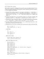
8.1.2.2 Example of SDL procedure implemented as a C function
We will modify our SDL V.76 model to replace the SDL procedure CRCok by the C function
CRCok.
A. Create a new directory, and copy all the files (except the MSCs) of the V.76 example into it.
B. Load v76.sdt in the Organizer.
C. If you added an observer process to the model as specified in Chapter 5, go back to the
version without observer process: in the Organizer, select Edit > Connect, choose To an
existing file, press the folder-shaped icon and connect to the file v76test.ssy.
D. In the Organizer, select the procedure CRCok and choose Edit > Disconnect, and press
Disconnect.
E. Open the package V76 and remove the procedure CRCok.
F. In the Organizer, press the Save button.
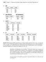
G. Open the process DLC, go to the page part2, and transform the call to CRCok as indi-
cated in Figure 8.2: the return value becomes an Integer instead of a Boolean, to simplify
the example.
H. With a text editor, create a file my
c.h containing the line shown in Figure 8.3.
PROCESS DLC (0, maxDLC + 1) part2(2)
CALL CRCok
(V76para ! I !CRC)
L_DataInd
(me, V76para!
I ! data)
-
I
0
-1
Figure 8.2 Modified call to procedure CRCok
extern int CRCok(int crc1);
Figure 8.3 The file my c.h
Other Simulator Features 269
I. In the Organizer, select the bar Used Files and press several times the Move Up button to
move it above the bar SDL System Structure.
J. Select the bar Used Files, choose Edit > Add Existing, select my
c.h and press Add.
K. Open the package V76 and add use ctypes; use my
c; as illustrated in Figure 8.4.
PACKAGE V76
use ctypes;
use my_c;
contents not shown
Figure 8.4 The package V76 modified
The clause use my c imports the SDL package my c generated by H2SDL (or by CPP2SDL)
because the file my
c.h has been added in the Organizer. The clause use ctypes imports the
SDL package ctypes required to import C into the SDL model.
L. With a text editor, create a file my
c.c as shown in Figure 8.5. The function CRCok is
defined, performing the same behavior as th e SDL version. Here you could paste an actual
CRC computation.
#include "my_c.h"
int CRCok(int crc1)
{
if (crc1<0) return -1;
else return 0;
}
Figure 8.5 The C function CRCok in the file my c.c
M. With a text editor, create a file my c.tpm containing the lines shown in Figure 8.6. This is
a template makefile, to compile the file my
c.c. Remember that the three last lines begin
with a tab character, not with spaces.
USERTARGET = my_c$(sctOEXTENSION)
my_c$(sctOEXTENSION): my_c.c
$(sctCC) $(sctCPPFLAGS) $(sctCCFLAGS) \
$(sctIFDEF) /Fomy_c$(sctOEXTENSION) \
my_c.c
Figure 8.6 The file my c.tpm
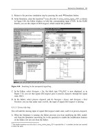
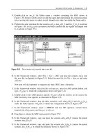
N. In the Organizer, select the system V76test and choose Generate > Make. Select Generate
makefile and use template and enter my
c.tpm as indicated in Figure 8.7. Select Microsoft
(or other) Simulation.PressFull Make: the executable V76test
smc.exe is generated.
270 Validation of Communications Systems with SDL
Figure 8.7 The SDL Make window set for simulation
O. The package ctypes has been added automatically to the Organizer. You can move it to the
Used Files part, as shown in Figure 8.8.
P. In the Organizer, press the Save button.
Q. In the Organizer, press the Simulate
button. Execute the command script cnx1.com,
send signal L
DataReq(0, 25) to process DLC in block DLCa, press the button Trace: SDL,
simulate using the Symbol button until the call to procedure CRCok, and check that the zero
answer is executed, as the parameter passed is positive.
8.1.3 Simulating ASN.1 data types
The Simulator and the Validator accept SDL models whose types are based on external ASN.1
modules, as described in [Z105
2]. ASN.1 is more powerful than the SDL data types, for
example, it allows the CHOICE construct (similar to a C union). In addition, several protocol
standards use ASN.1 to describe data.
8.1.4 Adding buttons to the Simulator
8.1.4.1 The three Simulator definition files
As shown in Figure 8.9, the buttons and menus present in the Simulator are defined in the file
def.btns. The content of the Command Window is defined in def.cmds, and the variables to
display in a watch are defined in def.vars.
The names and location of each definition file can be changed in the Preferences Manager
(from the Organizer). The Simulator loads the first of each file, searching in the following order:
the current directory, the user’s home directory and the installation directory.
Other Simulator Features 271
Figure 8.8 The Organizer after adding ctypes
def.btns
SDL
Simulator
def.cmds
def.vars
Buttons & menus
Command window
Variables in watch
Figure 8.9 The three Simulator definition files
8.1.4.2 Adding four buttons to the Simulator
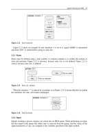
We are going to add two groups Service User A and Service User B to the Simulator. Then we
will add four buttons to these groups, as shown in Figure 8.10.
A. In the Simulator, select Buttons > Add Group,enterService User A and press Apply,enter
Service User B and press OK.
B. Press the button Group in Service User A and select Add.
C. Type EstabReq(0) in the field Label,andOutput-To L
EstabReq(0) <<Block DLCa>>
dispatch in the field Definition.PressApply.
D. Enter DataReq(0,5) in the field Label,andOutput-To L
DataReq (0, 5) <<Block DLCa>>
dispatch in the field Definition.PressApply.
E. Enter Release(0) in the field Label,andOutput-To L
ReleaseReq(0) <<Block DLCa>>
dispatch in the field Definition.PressOK.
272 Validation of Communications Systems with SDL
Figure 8.10 Four buttons added to the Simulator
F. Press the button Group in Service User B and select Add.
G. Type EstabResp in the field Label,andOutput-To L
EstabResp <<Block DLCb>> dispatch
in the field Definition.PressOK.
H. Save the buttons definitions: select Buttons > Save As and enter def.btns. At the next launch
of the Simulator, you will automatically get the newly created buttons.
I. You can now test the new buttons to transmit signals to the SDL model.
8.1.5 Adding buttons to the Validator
The same principles as those for the Simulator apply to add buttons to the Validator. Note
that the buttons defined in Section 8.1.4.2 cannot be used in the Validator, as the command
Output-To does not exist. The file names are different: def.btns becomes val
def.btns, def.cmds
becomes val
def.cmds and def.vars becomes val def.vars.
8.1.6 Setting breakpoints in the Simulator
Breakpoints can be specified in the Simulator, to stop the simulation when a certain SDL symbol
is reached, or on a transition, on a signal output, or on the modification of a variable. One or
more Simulator commands can be executed automatically when a breakpoint is reached.
To set a breakpoint on the input of signal V76frame in process type toPeer:
A. Start the Simulator on the V.76 model.
B. In the Simulator, select Breakpoint > Connect sdle.AnewBreakpoints menu appears in
the SDL Editor.
C. In the Editor, open the process type toPeer, select the input of signal V76frame and do
Breakpoints > Set Breakpoint :inthePrompt window, enter ex-pid. A red stop symbol
appears near the input, as shown in Figure 8.11.
PROCESS TYPE toPeer 1(1)
ready
V76frame
(V76par)
Figure 8.11 A breakpoint on an input symbol
Other Simulator Features 273
D. In the Simulator, press on Send To, select signal L SetParmReq, choose <<Block DLCa>>
dispatch, and press on Go: when the breakpoint is reached, the execution stops, and the
specified command ex-pid (Examine-Pid ) is executed:
Breakpoint matched at #SDTREF(SDL, topeer.spt(1),
140(35,35),1,1)
Instance of process type : toPeer
Parent : null
Offspring : null
Sender : <<Block DLCa>> dispatch:1
PId AtoB:1 in state ready
8.1.7 Running several communicating Simulators
Several Simulators can be started, and they can exchange SDL signals. For example, our V.76
SDL model can be split, and each instance of block type V76
DLC can run in one Simulator
and communicate with its peer instance running in the other Simulator.
A. Create a new directory, and copy all the files (except the MSCs) of the V.76 example into it.
B. Load v76.sdt in the Organizer.
C. If you added an observer process to the model as specified in Chapter 5, go back to the
version without observer process: in the Organizer, select Edit > Connect, choose To an
existing file, press the folder-shaped icon and connect to the file v76test.ssy.
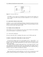
D. Open the system V76test and remove blocks DLCb and dataLink as indicated in Figure 8.12.
USE V76;
SYSTEM V76test 1(1)
DLCa : V76_DLC
DLCaSU
(su2dlc)
(dlc2su)
SU
DL
DLCaDL
V76frame
V76frame
to / from the other Simulator
Figure 8.12 System V76test split in two
E. In the Organizer, press the Save button, select the system V76test and select Generate >
Make. Check that the options are correct, especially: Microsoft (or other) Simulation and
Generate Makefile must be selected.
274 Validation of Communications Systems with SDL
F. Press Full Make.
G. In the Organizer, press the Simulate
button. The first Simulator starts.
H. In the Organizer, select Tools > SDL > Simulator UI. The second Simulator starts: select
File > Open and choose V76test
smc.exe (or the equivalent Unix suffix).
I. In each Simulator, select General > Start SDL Env: the two Simulators, represented in
Figure 8.13, can now exchange SDL signals (through the PostMaster).
v76frame
Figure 8.13 The two Simulators after the XID exchange
J. Simulate an XID exchange: in the first Simulator, transmit an L SetParmReq to process dis-
patch (using the button Send To), execute the transitions: the signal v76frame is transmitted
to the second Simulator. Execute the transitions to input it; after output of L
SetParmInd,
transmit an L
SetParmResp to process dispatch (always in the second Simulator), execute
the input transition: the signal v76frame is transmitted back to the first Simulator. In the
Other Simulator Features 275
first Simulator, you see the reception of v76frame. Execute the transitions to input it: an
L
SetParmConf is transmitted. The XID exchange is finished.
8.1.8 Real-time simulation
During simulation, the Simulator uses discrete time; after starting an SDL timer with a value
of five minutes, you are not forced to wait five minutes before its timeout: you can trigger the
timeout immediately. Note that the time unit is tool-dependent, here it is seconds (on Windows).
If necessary, for example, to run the Simulator connected to a real system, the Simulator can
run in real time: if you set a timer with a value of five minutes, it will actually timeout after
five minutes.To use real-time simulation, you must change the kernel used in the Organizer
Make window, as shown in Figure 8.14.
Figure 8.14 Selecting real-time simulation in the Make window
Then, if you set a ten-second SDL timer, you will see that the timeout occurs ten seconds
after pressing the Go Simulator button.
8.1.9 List of Validator options
Most of the important Validator options can be changed using Validator menus, but a few
require to type a textual command. To avoid using menus to change settings each time the
Validator is invoked, it is handy to put the corresponding textual commands into the Validator
startup file, valinit.com.
The following sections are presented in the same order as the result of the command show-
options.
8.1.9.1 Bit-state options
• Hash table size: 1000000 bytes: number of bytes in the hash table (1 byte can store 8 states).
Must be (in states or bits) 50 or 100 times the number of global system states to minimize
the collision risk.
• Search depth: 100: defines the maximum exploration depth; when reached, the Validator
backtracks to explore other transitions, the graph is truncated.
• Iteration Step: 0: do not use.
8.1.9.2 Exhaustive search option
• Search depth: 100: defines the maximum exploration depth; when reached, the Validator
backtracks to explore other transitions, the graph is truncated.
276 Validation of Communications Systems with SDL
8.1.9.3 Random walk options
• Search depth: 100: defines the maximum simulation depth; when reached, the random sim-
ulation stops, returns to the initial state and begins a new random simulation.
• Repetitions: 100: number of times the random simulation is restarted after reaching the search
depth. With 100, and a search depth of 100, the maximum number of transitions executed
will be 10000.
8.1.9.4 Tree search options
• Search depth: 100: defines the maximum simulation depth.
8.1.9.5 Power walk options
As this algorithm is designed for TTCN test case automatic generation for Autolink, to maximize
the SDL symbols coverage, we do not describe its options.
8.1.9.6 Autolink options
As Autolink is the tool used for TTCN test case automatic generation, we do not describe
its options.
8.1.9.7 Event priorities
This is used to change the priority between events during simulation. The default is maximum
priority (1) for internal events (inputs and outputs etc.) and channel output (if channel queues
are used), and lower priority (2) for input from ENV (input of external signals), timeout events
and spontaneous transition (input NONE). The menu command Options1 > Advanced assigns
the same priorities to all events, leading to richer behaviors but larger number of global states.
Event priorities: 1 2 3 4 5
Internal events : 1 0 0 0 0
Input from ENV : 0 1 0 0 0
Timeout events : 0 1 0 0 0
Channel output : 1 0 0 0 0
Spontaneous transition : 0 1 0 0 0
8.1.9.8 State space generation options
• Max input port length: 3: maximum number of signals present in each process input queue.
• Max symbols in transition: 1000: maximum number of symbols in a transition, useful to
detect infinite loops within a transition.
• Scheduling: First: the simulation uses a ready queue to execute first the oldest transition.
If changed to all, a more recent transition can be executed first, generally leading to richer
behaviors but larger number of global states.
Other Simulator Features 277
• Transition: SDL: do not use.
• Max no of instances: 100: do not use (seems equivalent to specifying the maximum number
of instances in the process reference in the SDL model).
• Spont. transition progress: On: means that a spontaneous transition (input none) is considered
as progress during nonprogress loop detection.
• Timer progress: On: means that a timer expiration is considered as progress during non-
progress loop detection.
• Timer check level: 1: when verifying an MSC, 0 means that checking of timer events is not
performed, 1 means that checking of timer events is performed, but a timer event can be
missing in the MSC, and 2 means that checking of timer events is performed and that timer
events in the SDL model and in the MSC must match exactly.
• MSC condition check: Off: conditions in MSC are ignored.
• Symbol time: Zero: if the SDL model is not blocked, a set timer cannot timeout. If set to
undefined, as soon as a timer is set, it can be timed-out.
• Max state size: 100000: do not change.
8.1.9.9 Report actions
The menu command Options1 > Report can be used to change the default actions after the
detection of an event triggering a report. The default is Prune – Log one for each event.
For example, by default, after reaching a state where the maximum number of signals in an
input queue is exceeded, the simulation does not continue beyond this state (prune means cut),
and backtracks to explore another state, if any. The other values are abort, meaning that the
simulation will stop, or continue, meaning that the simulation will continue beyond this state
and explore its successors.
Log one means that even if the event occurs more than once, only one report will be generated.
The other values are log all, where each occurrence of the event will generate a report, and log
off, where no report is generated.
Here is the list of reports sorted alphabetically, and their meaning:
• Assertion: the predefined procedure Report has been called (which calls the function xAs-
sertError ), generally from an observer process. See the observer process example.
• ChannelOutput: error in channel output, rarely used.
• Choice: error in CHOICE.
• Create: error in create.
• Deadlock: deadlock detected.
• Decision: error in a decision.
• ImplSigCons: implicit signal consumption, no input or save specified for a received signal.
• Import: error in import.
• Index: array index out of range.
278 Validation of Communications Systems with SDL
• Loop: loop in the states graph.
• MaxQueueLength: the maximum number of signals allowed in a process input queue has
been exceeded.
• MaxTransLen: infinite loop within a transition.
• MSCVerification: the MSC has been verified (the simulated behavior matches the MSC).
• MSCViolation: the MSC has been violated.
• Observer: an observer process has not been able to execute a transition.
• Operator: error in an SDL predefined operator.
• Optional: error in an ASN.1 optional field.
• Output: error in an output.
• PowerWalk: reports used for MSC and TTCN test cases generation (Autolink).
• RefError: concerns SDL models using pointers (an extension provided by Tau).
• Subrange: range overflow in a syntype value.
• TreeWalk: reports used for MSC and TTCN test cases generation (Autolink).
• UnionTag: error in an ASN.1 union.
• UserRule: a user-defined rule is satisfied.
• UserSpecified: not found in the Validator documentation.
• View: error in view-revealed.
8.1.9.10 MSC verification options
• Search depth: 1000: the maximum exploration depth (number of transitions) executed to
verify an MSC. When the depth is reached, the Validator backtracks and explores other
transitions, if any.
• Search mode: Violation: a fter trying this option, its effect has not been found.
• Algorithm: BitState: by default, a bit-state exploration is performed to try to verify the MSC.
The other alternative is TreeSearch.
• Ignore parameters: Off:ifsettoOn, MSC parameters are ignored.
8.1.9.11 Other options
• Report viewer autopopup: On: the Report Viewer will automatically appear after the end of
the Validation.
• MSC trace autopopup: On: the MSC Editor will automatically appear.
• MSC trace states: On: the state of SDL processes is written in the MSC trace.
Other Simulator Features 279
• MSC trace actions: Off: the actions (tasks etc.) executed are written in the MSC trace.
• MSC trace channels: Off: the env instance is not split into one instance for each channel
connected to env in the MSC trace.
8.2 OBJECTGEODE
8.2.1 Writing in the Simulator trace
To write a message in the Simulator trace window, the ObjectGeode-specific write and writeln
procedures can be called, from a procedure call symbol (if you use a task symbol, you will get
an error). Executing the example shown in Figure 8.15 produces the trace:
***n=0***
process test1
st1
WRITE
('***')
WRITELN
(' n = ' , n, ' ***')
st1
Figure 8.15 Calling write and writeln
8.2.2 Calling external C code
8.2.2.1 Introduction
You may want to reuse existing C code: for example, in the V.76 SDL model, instead of writing
a complex CRC (a kind of checksum) computation in the procedure CRCok, you could call an
existing C function.
The ObjectGeode Simulator provides several ways to call external C (or C++) code: SDL
operators and SDL procedures can be implemented as C functions. The same interfacing mech-
anism is provided in the ObjectGeode C application generator.
8.2.2.2 Example of SDL procedure implemented as a C function
We will modify our SDL V.76 model to replace the SDL procedure CRCok by the C function
crcok.
A. In a new empty directory, make a copy of any version of v76.pr (copy also v76.startup and
the files it loads), and load it into the SDL Editor.
280 Validation of Communications Systems with SDL
package V76
CRCok
This procedure
checks the CRC
procedure CRCok FPAR crc1 Integer RETURNS Boolean
Simplified version,
returns True if crc1
is positive or null.
crc1 >= 0
Figure 8.16 The procedure CRCok in SDL
B. In the package V76, delete the procedure CRCok shown in Figure 8.16.
C. In the package V76, create a text symbol containing the external declaration of procedure
CRCok, as shown in Figure 8.17.
package V76
PROCEDURE CRCok;
FPAR crc1 Integer;
RETURNS Boolean; EXTERNAL ;
Figure 8.17 The procedure CRCok declared external
D. Select Tools > SDL & MSC Simulator, and check that the working directory is correct.
E. In the ObjectGeode Launcher, remove any file other than v76.pr, and press the Build button:
as the keyword EXTERNAL has been used in the procedure declaration, the Simulator has
generated the file v76.h, shown in Figure 8.18, containing the declaration of crcok.
#ifndef CODE_INCLUDE_INCLUDED
#include "code_include.h"
#endif
#ifndef GEODESM2
This_file_can_only_be_used_with_ObjectGEODE_Simulator
#endif
#ifndef GEODESM_EXPORT
#define GEODESM_EXPORT
#include "hpredef.h"
typedef char SDL_CHARSTRING[GX_STRMAX];
struct _SDL_CHARSTRING_struct { SDL_CHARSTRING a; };
extern _SDL_CHARSTRING _SDL_CHARSTRING_empty;
#define SDL_CHARSTRING_empty (_SDL_CHARSTRING_empty.a)
extern SDL_BOOLEAN crcok (SDL_INTEGER crc1);
#endif
Figure 8.18 The generated file v76.h
F. Copy the file v76.h, rename it my c.c, and modify it to obtain the content shown in
Figure 8.19. The function crcok is defined, performing the same behavior as the SDL
version. Here you could paste an actual CRC computation.
Other Simulator Features 281
#include "v76.h"
/* Test of the CRC, simplified version: if
parameter crc1 is negative, the CRC is
incorrect else it is correct: */
SDL_BOOLEAN crcok (SDL_INTEGER crc1)
{
if (crc1<0) return SDL_FALSE;
else return SDL_TRUE;
}
Figure 8.19 The file my c.c
G. Create the file v76.lub (list of user binaries) as shown in Figure 8.20.
my_c.obj
geodecc_sm my_c.c
(a) (b)
Figure 8.20 The files (a) v76.lub and (b) geodesm ubld.bat
H. Create the file geodesm ubld.bat (geodesm ubld.cmd in Unix) as shown in Figure 8.20.
I. In the ObjectGeode Launcher, press again the Build button: the Simulator compiles the C
code generated from the SDL model, the file my
c.c, and generates the executable v76.sim
(the file hpredef.h is also generated).
J. Press the Execute button: the Simulator executes the SDL model plus the C function crcok.
8.2.3 Simulating ASN.1 data types
The Simulator accepts SDL models containing ASN.1 data types definitions, as described in
[Z105
1], with a few minor restrictions. ASN.1 is more powerful than the SDL data types, for
example, it allows the CHOICE construct (similar to a C union). In addition, several protocol
standards use ASN.1 to describe data.
8.2.4 Adding buttons to the Simulator
To simplify repetitive commands, buttons can be added to the Simulator interface. The default
button definitions are in the file geodesim.but located in the installation directory of Object-
Geode, as shown in Figure 8.21.
geodesim.but
SDL
Simulator
geodesim.but
In $(GEODE)/lib/geode_sm/
In current directory
Predefined buttons
Your buttons
Figure 8.21 The Simulator button definition files
282 Validation of Communications Systems with SDL
If a file named geodesim.but is found in the current directory, the Simulator loads button
definitions from it, and will not read the file geodesim.but in the installation directory.
If you put the file depicted in Figure 8.22 into your current directory, the Simulator will have
three more buttons, as shown in Figure 8.23.
! To get also the Simulator standard buttons:
include "$(GEODE)/lib/geode_sm/geodesim.but"
Panel main
{
"____________" label
"V.76 test" label
! Inits the Simulation and plays start.scn:
"Re-init V.76" cmd init; source start.scn
! Inits the Simulation and plays cnx1.scn:
"Connect DLC 0" cmd init; source cnx1.scn; print state
! Displays the name of the first signal in the queues:
"Queues head" cmd echo "Input queues head:"; print pr(1)!queue(1)!name \
for all pr in process if length(pr(1)!queue)/=0
" " label
}
Figure 8.22 The file geodesim.but
Figure 8.23 Three buttons added to the Simulator
The first statement includes the file containing the standard button definitions, then three
buttons specific to the V.76 model are added to the main Simulator panel. The first button
reinitializes the model to Step 4, ready to begin a simulation, automatically executing the
process start transitions. The second button places the model in a state where DLC number 0
is established. The last button displays the name of the first signal present in the queue of each
process instance.
It is also easy to create a button opening a new panel with specific buttons, such as the panel
opened by the button Verify.
8.2.5 Simulation scheduling like in Tau SDL Simulator and Validator
When an SDL model contains many process instances, the list of firable transitions in the
Simulator can be sometimes long. This is compliant with the execution semantics of SDL.
Other Simulator Features 283
The ObjectGeode Simulator (like the Tau SDL Validator when using the command Define-
Scheduling All ) does not use a ready queue like the Tau SDL Simulator, to propose only the
oldest transitions, but proposes all the ready transitions at the same time.
To simplify the choice by reducing the number of transitions, a GOAL observer delivered
with ObjectGeode, named scheduling, can be compiled with any SDL model.
To illustrate this, we have created the SDL model test1, represented in Figures 8.24 and 8.25.
This model contains one process TX transmitting sig1 to process RX
1 and then sig2 to process
RX
2.
block sched
SIGNAL
sig1, sig2;
sr1
sig1
sr2
sig2
TX
RX_1
RX_2
system test1
sched
Figure 8.24 The system test1
process TX
sig1
sig2
ready
ready
process RX_1
wait
sig1
-
process RX_2
wait
sig2
-
Figure 8.25 The three processes in block sched
By default, after executing process TX, the Simulator proposes two transitions:
• input of sig1 by RX
1 and
• input of sig2 by RX
2
To use the scheduling observer:
A. Create the model test1 with the SDL Editor (or load any model of your choice).
B. In the SDL Editor, select File > Load, change the File type to *.obs and
select Og
sdl\examples\geode sm\scheduling\scheduling.obs in ObjectGeode installation
directory.
C. Select Tools > SDL & MSC Simulator, and check that the working directory is correct.
284 Validation of Communications Systems with SDL
D. In the ObjectGeode Launcher, press Build and then press Execute.
E. Execute the three start transitions (double-click on them). There are two firable transitions:
rx_1(1) : from_wait_input_sig1
rx_2(1) : from_wait_input_sig2
F. In the Simulator, type the textual command: filter scheduling!filter. There is now only one
firable transition, corresponding to the first process that is ready (because it received a signal
before process RX
2 ):
rx_1(1) : from_wait_input_sig1
G. Execute the transition. As expected, the second transition appears:
rx_2(1) : from_wait_input_sig2
8.2.6 List of Simulator settings
8.2.6.1 Define commands
Most of the important Simulator settings can be changed using Simulator menus, but others
require to type a define command. To avoid using menus to change settings each time the
Simulator is invoked, it is handy to put the corresponding define commands into a Simulator
startup file.
The following list is the result of the command define, sorted alphabetically. A few defines
listed below are absent from the Simulator documentation.
• define alpha
order trans ‘true’: if true, the firable transitions are sorted alphabetically.
• define build
graph ‘false’: do not use.
• define call
depth limit ‘100’: limits to 100 the number of recursive procedure calls.
• define client
external encoding ‘true’: do not use.
• define client
external env ‘true’: do not use.
• define client
external processes ‘false’: do not use.
• define compose
unit ‘0’: if not 0, a second level of global states compression is performed.
• define compress
unit ‘0’: if not 0, a second level of global states compression is performed.
• define coverage
go ‘false’: do not use.
• define coverage
list ‘false’: if true, the Simulator displays in front of each firable transition
the number of times it has been simulated.
• define depth
limit ‘0’: defines the maximum depth during exhaustive simulation. If 0, no limit.
• define depth
limit stop ‘false’: if false, the exhaustive simulation explores another branch of
the states graph when depth
limit is reached, otherwise the exhaustive simulation stops.
• define edges
dump ‘ ’:ifaname is specified between the single quotes, the transitions of
the states graph are written into the file name. For training only.
Other Simulator Features 285
• define expand limit ‘20’: when calling an undefined SDL operator, if the return type has
less than 20 values, then one firable transition will be proposed for each value, otherwise a
window will prompt the user for the value.
• define flush
log file ‘true’: do not use.
• define forced
interactive ‘false’: do not use.
• define graph
file ‘ ’: do not use.
• define hash
fill limit ‘10’: specifies the first (default) level of global states compression (no
effect on supertrace). The second level is set by compose
unit and compress unit.
• define hash
size ‘1000’: specifies the first (default) level of global states compression (no
effect on supertrace).
• define HOME ‘C:\WINNT\Profiles\Administrateur\ObjectGEODE ’: the location of the cur-
rent home directory.
• define loose
time ‘false’: see Chapter 4.
• define main
hash size ‘100000’: specifies the first (default) level of global states compression
(no effect on supertrace).
• define map
1param signal to sequence ‘false’: reserved for TTCN test case generation.
• define marglim ‘1000’: used for performance simulation.
• define max
lines watch ‘1000’: defines the maximum lines displayed in a watch window.
• define MODEL ‘ping’: current SDL file name.
• define msc
always dynamic ‘true’: if true, the MSC trace is updated during automatic sim-
ulation (go, redo etc.), otherwise it is updated after the end of the execution.
• define msc
fly ‘true’: if true, an MSC trace is created during the simulation.
• define msc
global ‘true’: if true, time in the generated MSC trace is global, otherwise local
to each instance.
• define msc
xspace ‘140’: horizontal space between two instances in the generated MSC trace;
it seems that this option is no longer active, especially on the Windows version.
• define msc
yspace ‘20’: same as above for the vertical space between two signals.
• define mscinst
by event ‘true’: if true, the MSC instances are placed in their order of chrono-
logical appearance, otherwise the instances are placed according to the msc for command
(i.e. if you type msc for proc1, proc2, if true you get proc1 drawnontheleftandproc2 on
the right, even if proc2 is first to receive a signal). Very handy to avoid reordering instances
after MSC generation.
• define print
filter condition errors ‘false’: do not use.
• define print
hook ‘ ’: if a name is entered, the user-defined printing operators (useful for
opaque Abstract Data Types, especially if implemented in C) matching this name are exe-
cuted. For example, if you define the type:
NEWTYPE opaque1
OPERATORS
286 Validation of Communications Systems with SDL
print1: opaque1 -> Boolean;
OPERATOR print1;
FPAR p1 opaque1; RETURNS res Boolean;
START;
WRITELN(’*** Hello world!’);
RETURN True;
ENDOPERATOR;
ENDNEWTYPE;
If you declare a variable x of type opaque1 in the SDL model, when you enter the command
print x, you get no result because the Simulator does not know what to print (because the
NEWTYPE opaque1 is neither a struct, nor a literals list, nor an array etc.). If you enter
define print
hook ‘pr*’, then typing print x activates the operator print1 and *** Hello world!
is displayed.
• define print
stop condition errors ‘false’: do not use.
• define range
check ‘false’: if true, the range overflow is checked when the Simulator evaluates
a command containing ranges.
• define real
prec ‘6’: number of digits after the decimal point for real numbers.
• define reasonable feed ‘true’: see Chapter 4.
• define run
forever ‘false’: do not use.
• define scc sink limit ‘2’: maximum number of livelock scenario files generated during an
exhaustive simulation, here 2.
• define show
optionals ‘false’: prevents the Simulator from displaying the OPTIONAL fields
(generally from ASN.1) that are not present in the value of the sequence.
• define significance
level ‘0.05’: used for performance simulation.
• define states
dump ‘ ’:ifaname is specified between the single quotes, the states of the
states graph are written into the file name. For training only.
• define states
limit ‘0’: maximum number of explored (unique) global states. When the limit
is reached, the exhaustive simulation stops. 0 means no limit. In supertrace mode, it specifies
the number of bits in the hash table, which must be 50 or 100 times the number of global
system states to minimize the collision risk.
• define stop
cut ‘true’: if true, the states after a state where a stop condition is satisfied are
not explored (cut is equivalent to prune in Tau Validator).
• define tc
engine ‘default’: reserved for TTCN test case generation.
• define time
horizon ‘10000.0’: used for performance simulation.
• define timescale ‘1’: contains the value specified for the timescale option when launching the
Simulator. Cannot be changed.
• define tp
coverage ‘0%’: reserved for TTCN test case generation.
Other Simulator Features 287
• define tp coverage limit ‘100’: reserved for TTCN test case generation.
• define tp
dir ‘.’: reserved for TTCN test case generation.
• define tp
interpretation ‘complete’: reserved for TTCN test case generation.
• define tp
msc gen ‘false’: reserved for TTCN test case generation.
• define tp
obs step ‘true’: reserved for TTCN test case generation.
• define trace
stmt ‘true’: when true, the SDL statements are traced in PR (textual) form in
the Simulator window.
• define trans
events limit ‘1000’: used to detect infinite loops in the SDL model. Here, after
1000 events, the transition is considered infinite and an error is reported.
• define trap
multiple receiver ‘true’: when true, detects an error if a signal (or a remote
procedure call) is transmitted and several process instances can receive it through the same
path (channels and routes). When false, no error is raised, as specified in [SDL92]. If the
signal can be received through different paths, no error is raised, as specified in [SDL92].
• define trap
no receiver ‘true’: when true, detects an error if a signal (or a remote procedure
call) is transmitted and no receiver exists (for example, the process instance has stopped).
When false, no error is raised and the signal is discarded, as specified in [SDL92].
• define trap
unexpected signal ‘true’: when true, detects an error if a signal is transmitted
and no input exists for such signal in the current state of the receiver. When false, no error
is raised and the signal is discarded, as specified in [SDL92].
• define ts
controllable ‘true’: reserved for TTCN test case generation.
• define ts
default testcase ‘DEF 0’: reserved for TTCN test case generation.
• define ts
language ‘text’: reserved for TTCN test case generation.
• define ts
name ‘ping’: reserved for TTCN test case generation.
• define ts
purpose comment ‘from state %s of %p, receive %i, send (%o) and go to state %f’:
reserved for TTCN test case generation.
• define ts
test groups ‘false’: reserved for TTCN test case generation.
• define ts
test steps ‘false’: reserved for TTCN test case generation.
• define verify
stats ‘true’: when true, the number of states for each process and each input
queue is displayed at the end of an exhaustive simulation. A must to detect which queues
contain too many signals and must be limited using the filter command.
• define watch
expand depth ‘3’: number of levels displayed expanded in a watch.
• define windows ‘true’: true if Windows is used, otherwise false (Unix).
8.2.6.2 Other settings
A few Simulator settings are not define commands. They are displayed textually by typing the
command verify options. As the define commands, they can be put into a Simulator startup file.