transformer engineering design and practice 1_phần 9 pdf
Bạn đang xem bản rút gọn của tài liệu. Xem và tải ngay bản đầy đủ của tài liệu tại đây (677.29 KB, 49 trang )
277
7
Surge Phenomena in Transformers
For designing the insulation of a transformer suitable for all kinds of overvoltages,
the voltage stresses within the windings need to be determined. For this purpose,
voltage distributions within the transformer windings for the specific test voltages
are calculated. For AC test voltages of power frequency, the voltage distribution is
linear with respect to the number of turns and can be calculated exactly. For the
calculation of the impulse voltage distribution in the windings, they are required
to be simulated in terms of an equivalent circuit consisting of lumped R, L and C
elements. There are a number of accurate methods described in the literature for
computation of winding response to impulse voltages, some of which are
discussed in this chapter. Electric stresses in the insulation within and outside the
windings are obtained by analytical or numerical techniques which are described
in the next chapter.
7.1 Initial Voltage Distribution
When a step voltage impinges on the transformer winding terminals, the initial
distribution in the winding depends on the capacitances between turns, between
windings, and those between windings and ground. The winding inductances have
no effect on the initial voltage distribution since the magnetic field requires a finite
time to build up (current in an inductance cannot be established instantaneously).
Thus, the inductances practically do not carry any current, and the voltage
distribution is predominantly decided by the capacitances in the network, and the
problem can be considered as entirely electrostatic without any appreciable error.
In other words, the presence of series capacitances between winding sections
causes the transformer to respond to abrupt impulses as a network of capacitances
for all frequencies above its lower natural frequencies of oscillations. When the
applied voltage is maintained for a sufficient time (50 to 100 microseconds),
Copyright © 2004 by Marcel Dekker, Inc.
Chapter 7278
appreciable currents begin to flow in the inductances eventually leading to the
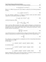
uniform voltage distribution. Since there is difference between the initial and final
voltage distributions, as shown in figure 7.1, a transient phenomenon takes place
during which the voltage distribution readjusts itself from the initial to final value.
During this transient period, there is continual interchange of energy between
electric and magnetic fields. On account of a low damping factor of the
transformer windings, the transient is oscillatory. The voltage at any point in the
winding oscillates about the final voltage value, reaching a maximum as shown by
curve c. It is obvious that the strength of the transformer windings to lightning
voltages can be significantly increased if the difference between the initial and
final distributions can be minimized. This not only reduces the excessive stresses
at the line end but also mitigates the oscillations thereby keeping voltage to ground
at any point in the winding insignificantly higher than the final voltage
distribution.
The differential equation governing the initial voltage distribution u
0
=u(x,0),
for the representation of a winding shown in figure 7.2 (and ignoring inductive
effects), is [1]
(7.1)
In figure 7.2, L
s
, c
g
and c
s
denote self inductance per unit length, shunt capacitance
per unit length to ground and series capacitance per unit length between adjacent
turns respectively.
Figure 7.1 Impulse voltage distribution
Copyright © 2004 by Marcel Dekker, Inc.
Surge Phenomena in Transformers 279
Solution of the above equation is given by
µ
0
=A
1
e
kx
+A
2
e
-kx
(7.2)
where
(7.3)
The constants of integration A
1
and A
2
can be obtained from the boundary
conditions at the line and neutral ends of the winding. For the solidly grounded
neutral, we have µ
0
=0 for x=0. Putting these values in equation 7.2 we get
A
1
+A
2
=0 or A
1
=-A
2
Whereas at the line end, x=L (L is the winding axial length) and u
0
=U (amplitude
of the step impulse voltage) giving
(7.4)
Substituting the above expression in equation 7.2 we get
(7.5)
The initial voltage gradient at the line end of the winding is given by
Figure 7.2 Representation of a transformer winding
Copyright © 2004 by Marcel Dekker, Inc.
Chapter 7280
(7.6)
The initial voltage gradient is maximum at the line end. Since kL>3 in practice,
coth
giving the initial gradient at the line end for a unit amplitude surge
(U=1)as
(7.7)
The uniform gradient for the unit amplitude surge is 1/L.
(7.8)
where C
G
and C
S
are the total ground capacitance and series capacitance of the
transformer winding respectively. The ratio has been denoted by the
distribution constant
α
. Thus, the maximum initial gradient at the line end is
α
times the uniform gradient. The higher the value of ground capacitance, the higher
are the values of
α
and voltage stress at the line end.
For the isolated neutral condition, the boundary conditions,
give the following expression for the initial voltage distribution:
(7.9)
For the isolated neutral condition, the maximum initial gradient at the line end can
be written as
(7.10)
For a unit amplitude surge and (
α
=kL)>3, Hence, the initial gradient
becomes
(7.11)
Copyright © 2004 by Marcel Dekker, Inc.
Surge Phenomena in Transformers 281
Hence, the value of maximum initial gradient at the line end is the same for the
grounded and isolated neutral conditions for abrupt impulses or very steep wave
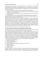
fronts. The initial voltage distribution for various values of a is plotted in figure
7.3 for the grounded and isolated neutral conditions. The total series capacitance
(C
S
) and ground capacitance (C
G
) of the transformer winding predominantly
decide the initial stresses in it for steep fronted voltage surges. The total series
capacitance consists of capacitance between turns and capacitance between disks/
sections of the winding, whereas the total ground capacitance includes the
capacitance between the winding and core/tank/other windings. Thus, the initial
voltage distribution is characterized by the distribution constant,
(7.12)
This parameter indicates the degree of deviation of the initial voltage distribution
from the final linear voltage distribution which is decided solely by winding
inductances. The higher the value of
α
, the higher are the deviation and
amplitudes of oscillations which occur between the initial and final voltage
distributions. For a conventional continuous disk winding, the value of
α
may be
in the range of 5 to 30. Any change in the transformer design, which decreases the
distribution constant of the winding, results in a more uniform voltage distribution
and reduces the voltage stresses between different parts of the winding. The initial
voltage distribution of the winding can be made closer to the ideal linear
distribution (
α
=0) by increasing its series capacitance and/ or reducing its
capacitance to ground. If the ground capacitance is reduced, more current flows
through the series capacitances, tending to make the voltage across the various
winding sections more uniform. The (ideal) uniform initial impulse voltage
distribution will be achieved if no current flows through the (shunt) ground
capacitances. Usually, it is very difficult and less cost-effective to reduce the
Figure 7.3 Initial voltage distribution
Copyright © 2004 by Marcel Dekker, Inc.
Chapter 7282
ground capacitances. Insulation gaps between windings predominantly decide the
ground capacitances. These capacitances depend on the radial gap and
circumferential area between the windings. These geometrical quantities get
usually fixed from optimum electrical design considerations. Hence, any attempt
to decrease the distribution constant
α
by decreasing the ground capacitance is
definitely limited. The more cost-effective way is to increase the winding series
capacitance by using different types of windings as described in the subsequent
sections.
7.2 Capacitance Calculations
In order to estimate the voltage distribution within a transformer winding
subjected to impulse overvoltages, the knowledge of its effective series and
ground capacitances is essential. The calculation of ground capacitance between a
winding and ground or between two windings is straightforward. The capacitance
between two concentric windings (or between the innermost winding and core) is
given by
(7.13)
where D
m
is mean diameter of the gap between two windings, t
oil
and t
solid
are
thicknesses of oil and solid insulations between two windings respectively, and H
is height of windings (if the heights of two windings are unequal, average height is
taken in the calculation).
Capacitance between a cylindrical conductor and ground plane is given by
(appendix B, equation B30)
(7.14)
where R and H are radius and length of the cylindrical conductor respectively and
s is distance of center of the cylindrical conductor from the plane. Hence, the
capacitance between a winding and tank can be given as
(7.15)
In this case, R and H represent the radius and height of the winding respectively
and s is the distance of the winding axis from the plane. The capacitance between
the outermost windings of two phases is half the value given by above equation
Copyright © 2004 by Marcel Dekker, Inc.
Surge Phenomena in Transformers 283
7.15, with s equal to half the value of distance between the axes of the two
windings (refer to equation B28).
7.3 Capacitance of Windings
7.3.1 Development of winding methods for better impulse response
In the initial days of transformer technology development for higher voltages, use
of electrostatic shields was quite common (see figure 7.4). A non-resonating
transformer with electrostatic shields was reported in [2,3,4]. It is a very effective
shielding method in which the effect of the ground capacitance of individual
section is neutralized by the corresponding capacitance to the shield. Thus, the
currents in the shunt (ground) capacitances are supplied from the shields and none
of them have to flow through the series capacitances of the winding. If the series
capacitances along the windings are made equal, the uniform initial voltage
distribution can be achieved. The electrostatic shield is at the line terminal
potential and hence requires to be insulated from the winding and tank along its
height. As the voltage ratings and corresponding dielectric test levels increased,
transformer designers found it increasingly difficult and cumbersome to design
the shields. The shields were found to be less cost-effective since extra space and
material were required for insulating shields from other electrodes inside the
transformer. Subsequent development of interleaved windings phased out
completely the use of electrostatic shielding method. The principle of electrostatic
shielding method is being made use of in the form of static end rings at the line end
and static rings within the winding which improve the voltage distribution and
reduce the stresses locally.
Figure 7.4 Electrostatic shields
Copyright © 2004 by Marcel Dekker, Inc.
Chapter 7284
In order to understand the effectiveness of an interleaved winding, let us first
analyze a continuous (disk) winding shown in figure 7.5. The total series
capacitance of the continuous winding is an equivalent of all the turn-to-turn and
disk-to-disk capacitances. Although the capacitance between two adjacent turns is
quite high, all the turn-to-turn capacitances are in series, which results in a much
smaller capacitance for the entire winding. Similarly, all the disk-to-disk
capacitances which are also in series, add up to a small value. With the increase in
voltage class of the winding, the insulation between turns and between disks has
to be increased which further worsens the total series capacitance.
The inherent disadvantage of low series capacitance of the continuous winding
was overcome by electrostatic shielding as explained earlier till the advent of the
interleaved winding. The original interleaved winding was introduced and
patented by G.F.Stearn in 1950 [5]. A simple disposition of turns in some
particular ways increases the series capacitance of the interleaved winding to such
an extent that a near uniform initial voltage distribution can be obtained. A typical
interleaved winding is shown in figure 7.6.
Figure 7.5 Continuous winding
Figure 7.6 Interleaved winding
Copyright © 2004 by Marcel Dekker, Inc.
Surge Phenomena in Transformers 285
In an interleaved winding, two consecutive electrical turns are separated
physically by a turn which is electrically much farther along the winding. It is
wound as a conventional continuous disk winding but with two conductors. The
radial position of the two conductors is interchanged (cross-over between
conductors) at the inside diameter and appropriate conductors are joined at the
outside diameter, thus forming a single circuit two-disk coil. The advantage is
obvious since it does not require any additional space as in the case of complete
electrostatic shielding or part electrostatic shielding (static ring). In interleaved
windings, not only the series capacitance is increased significantly but the ground
capacitance is also somewhat reduced because of the improvement in the winding
space factor. This is because the insulation within the winding in the axial
direction can be reduced (due to improvement in the voltage distribution), which
reduces the winding height and hence the ground capacitance. Therefore, the
distribution constant (
α
) is reduced significantly lowering stresses between
various parts of the winding.
It can be seen from figure 7.6 that the normal working voltage between
adjacent turns in an interleaved winding is equal to voltage per turn times the turns
per disk. Hence, one may feel that a much higher amount of turn insulation may be
required, thus questioning the effectiveness of the interleaved winding. However,
due to a significant improvement in the voltage distribution, stresses between
turns are reduced by a great extent so that % safety margins for the impulse stress
and normal working stress can be made of the same order. Hence, the turn-to-turn
insulation is used in more effective way [6]. Since the voltage distribution is more
uniform, the number of special insulation components (e.g., disk angle rings)
along the winding height reduces. When a winding has more than one conductor
per turn, the conductors are also interleaved as shown in figure 7.7 (a winding with
6 turns per disk and two parallel conductors per turn) to get maximum benefit
from the method of interleaving.
Figure 7.7 Interleaving with 2-parallel conductors per turn
Copyright © 2004 by Marcel Dekker, Inc.
Chapter 7286
In [7], improved surge characteristics of interleaved windings are explained
based on transmission line like representation of the disks with surge impedance,
without recourse to the hypothesis of increased series capacitance.
There can be two types of interleaved windings as regards the crossover
connections at the inside diameter as shown in figure 7.8. When steep impulse
waves such as chopped waves or front-of-waves enter an interleaved winding, a
high oscillatory voltage occurs locally between turns at the center of the radial
build of the disk. This phenomenon is analyzed in [8,9] for these two types of
crossovers in the interleaved windings.
7.3.2 Turn-to-turn and disk-to-disk capacitances
For the calculation of series capacitances of different types of windings, the
calculations of turn-to-turn and disk-to-disk capacitances are essential. The turn-
to-turn capacitance is given by
(7.16)
where D
m
is average diameter of winding, w is bare width of conductor in axial
direction, t
p
is total paper insulation thickness (both sides),
ε
0
is permittivity of the
free space, and
ε
p
is relative permittivity of paper insulation. The term t
p
is added to
the conductor width to account for fringing effects.
Similarly, the total axial capacitance between two consecutive disks based on
geometrical considerations only is given by
(7.17)
where R is winding radial depth, t
s
and
ε
s
are thickness and relative permittivity of
solid insulation (radial spacer between disks) respectively, and k is fraction of
circumferential space occupied by oil. The term t
s
is added to R to take into
account fringing effects.
Figure 7.8 Two types of crossovers in interleaved winding
Copyright © 2004 by Marcel Dekker, Inc.
Surge Phenomena in Transformers 287
For continuous winding and its variations (with static end rings/static rings
between disks), there are two approaches for calculating the series capacitance. In
the first approach, the voltage is assumed to be evenly distributed within the disk
winding, which makes the calculation quite easy. However, this is a major
approximation for continuous disks having small effective inter-turn series
capacitance. Hence, the second approach is more accurate in which the linear
voltage distribution is not assumed within the disks for the capacitance calculation
[10,11,12]. The corresponding representation of capacitances for this accurate
method of calculation is shown in figure 7.9. The total series capacitance of the
winding is given by [10,13]
(7.18)
where C
DA
=disk-to-disk capacitance calculated based on geometrical
considerations
α
d
=distribution constant of disk =
C
T
=turn-to-turn capacitance
N
D
=number of turns per disk
N
DW
=number of disks in the winding
Figure 7.9 Representation of capacitances of a continuous winding
Copyright © 2004 by Marcel Dekker, Inc.
Chapter 7288
The first approach, in which linear voltage distribution is assumed for
capacitance calculations, is definitely approximate for continuous windings. The
total series capacitance of a disk is small and also the disk-to-disk capacitance
(C
DA
) is appreciable, making the distribution constant
α
d
for the disk larger. Hence,
the voltage distribution within the disk and within the winding is non-linear.
However, the approach is easier and the expressions obtained for the capacitances
of various types of windings can be easily compared. The approach is used in the
following sub-sections for the calculation of the series capacitance of various
windings including continuous windings.
7.3.3 Continuous disk winding
Let us find the capacitance of a disk pair of a continuous winding shown in figure
7.10 with the assumption of linear voltage distribution. The term C
T
denotes
capacitance between touching turns and C
D
denotes capacitance between a turn of
one disk and the corresponding turn of the other disk. If N
D
is number of turns in a
disk, then number of inter-turn capacitances (C
T
) in each disk is (N
D
-1). Also,
number of inter-section capacitances (C
D
) between the two disks is (N
D
-1). The
series capacitance of the disk winding is the resultant of the inter-turn (turn-to-
turn) and inter-disk (disk-to-disk) capacitances. The voltage per turn for the disk
pair shown in figure 7.10 is (V/2N
D
). Using the principle that the sum of energies
in the individual capacitances within the disk is equal to the entire energy of the
disk coil, the following equation can be written:
where C
TR
=resultant inter-turn capacitance.
(7.19)
Figure 7.10 Disk-pair of a continuous winding
Copyright © 2004 by Marcel Dekker, Inc.
Surge Phenomena in Transformers 289
Now, the voltages across the first, second and third inter-disk capacitances (C
D
)
from the inside diameter are
Hence, the expression for C
D
at the outside diameter is
The total energy stored by all such capacitances is
(7.20)
Simplifying and using the identity:
we get
(7.21)
where C
DR
is the resultant inter-disk capacitance.
(7.22)
Instead of using the lumped parameter approach for the inter-disk capacitances, if
they are represented by a distributed capacitance C
DU
(capacitance per unit radial
depth based on the geometrical considerations only), then the value of resultant
inter-disk capacitance for aradial depth of R can be calculated as [14]
(7.23)
The previous two equations are equivalent, because if the number of turns per disk
is much greater than 1(N
D
>>1), equation 7.22 becomes
The resultant series capacitance of the disk pair is given as the addition of the
resultant inter-turn capacitance and the resultant inter-disk capacitance,
. (7.24)
Copyright © 2004 by Marcel Dekker, Inc.
Chapter 7290
or
(7.25)
Now, if there are N
DW
disks in the winding, the resultant inter-disk capacitance
(C
DR
)
W
for the entire winding (with a voltage V
w
across it) can be calculated as
(7.26)
(7.27)
Noting the fact that the expression for C
TR
given by equation 7.19 is for two disks,
the total series capacitance for the entire winding with N
DW
disks can be given by
using equations 7.19 and 7.27 as
(7.28)
The above expression gives the value of capacitance close to that given by
equation 7.18 for the values of disk distribution constant
α
d
close to 1 (almost
linear distribution within disk). For N
DW
, N
D
>>1, the equation 7.28 becomes
(7.29)
7.3.4 Continuous winding with SER and SR
As mentioned earlier, the concept of electrostatic shielding is used in a limited
way by having a static end ring (SER) at line end or a static ring (SR) between
disks as shown in figure 7.11.
Figure 7.11 Static end ring (SER) and static ring (SR)
Copyright © 2004 by Marcel Dekker, Inc.
Surge Phenomena in Transformers 291
By providing a large equipotential surface with a good corner radius, SER
reduces the stress concentration at the line end. It also improves the effective
series capacitance at the line end as explained below. The closer the location of
SER to the line end disk, the greater the increase in the series capacitance value is.
This results in reduction of stresses appearing within the line end disk during the
initial voltage distribution.
Let us calculate the increase in series capacitance of a disk pair with SER as per
the method given in [14]. SER is usually connected to the first turn of the winding
by means of a pig-tail; hence the potential of SER gets fixed to that of line terminal
(V) as shown in figure 7.12. Let the winding radial depth be denoted by R.
The voltage at any point x of the upper section representing SER is
V
1
(x)=V (7.30)
and the voltage at any point x of the lower section representing the first disk is
(7.31)
Let C
SU
be the capacitance between SER and the first disk per unit depth of the
winding (based on the geometrical considerations only). Therefore, the energy of
the capacitance C
SU
per unit depth at point x is
(7.32)
Figure 7.12 Calculation of capacitance between SER and line end disk
Copyright © 2004 by Marcel Dekker, Inc.
Chapter 7292
The total energy stored by the capacitance between the first disk and SER is
(7.33)
Substituting the values of V
1
(x) and V
2
(x) from equations 7.30 and 7.31, and
simplifying we get
(7.34)
Thus, the resultant capacitance, C
SER
, between SER and the first disk can be given
by the equation
(7.35)
(7.36)
Thus, the resultant capacitance between SER and the first disk is (1/12) times the
capacitance obtained purely from the geometrical considerations.
Using equations 7.25 and 7.36, the total series capacitance of the disk pair with
SER is therefore given by
(7.37)
Similarly, the expression for the series capacitance of a disk-pair with static ring
(shown in figure 7.11) can be found as
(7.38)
where the first, second and third terms on right hand side of the above equation
represent the inter-turn capacitances, first disk to SR capacitance, and SR to
second disk capacitance respectively. Here, it is assumed that the gap between the
first disk and SR is equal to the gap between SR and the second disk.
7.3.5 Interleaved winding
As explained earlier, an interleaved winding results in a considerable increase of
series capacitance. In this type of winding, geometrically adjacent turns are kept
far away from each other electrically, so that the voltage between adjacent turns
Copyright © 2004 by Marcel Dekker, Inc.
Surge Phenomena in Transformers 293
increases. By interleaving the turns in such a way, the initial voltage distribution
can be made more uniform. The capacitance between the disks (inter-disk
capacitance) has very little effect on the series capacitance of this type of winding
since its value is relatively low. Therefore, it is sufficient to consider only the inter-
turn capacitances for the calculation of series capacitance of the interleaved
windings. It follows that for the interleaved windings, the second approach of
capacitance calculation based on the assumption of linear voltage distribution is
quite accurate as compared to the continuous windings.
For the interleaved winding shown in figure 7.6, the number of inter-turn
capacitances per disk is (N
D
-1). The total number of inter-turn capacitances in a
disk-pair is 2(N
D
-1). As before, let V be the voltage applied across the terminals of
the disk-pair. The voltage is assumed to be uniformly distributed over the disk-
pair; the assumption is more appropriate for interleaved windings as explained
earlier. For the interleaved winding shown in figure 7.6, the number of electrical
turns between the first and second turn is 10, while that between the second and
third turn is 9. This arrangement repeats alternately within the disks. Hence, the
voltage across the N
D
capacitances is (V/2) and across the remaining (N
D
–2)
capacitances is The energy stored in the disk-pair is given by
(7.39)
For N
D
>>1, the expression simplifies to
(7.40)
The interleaving of turns can give a substantial increase in the series
capacitance of a winding and hence interleaved windings are used widely in high
voltage transformers. As the rating of power transformer increases, higher core
diameters are used increasing the voltage per turn value. Hence, a high voltage
winding of a large rating transformer has usually lower turns and correspondingly
lower turns per disk as compared to a high voltage winding of the same voltage
class in a lower rating transformer. Since the interleaved windings are more
effective for higher turns per disk, they may not be attractive for use in high-
voltage high-rating transformers. Added to this, as the rating increases, the current
Copyright © 2004 by Marcel Dekker, Inc.
Chapter 7294
carried by the high voltage winding increases, necessitating the use of a large
number of parallel conductors for controlling the winding eddy losses. The
interleaved winding with a large parallel conductors is difficult from productivity
point of view. Hence, an alternative method of increasing capacitance by use of
shielded-conductor (wound-in-shields) is adopted for high voltage windings of
large power transformers. This is because of the fact that the continuously
transposed cable (CTC) conductor, which is ideally suited for such applications
(as explained in Chapter 4), can be used with this shielded-conductor winding
technology.
7.3.6 Shielded-conductor winding
A shielded-conductor winding gives a modest but sufficient increase in the series
capacitance and is less labour intensive as compared to an interleaved winding.
The number of shielded-conductors can be gradually reduced in the shielded disks
from the line end, giving a possibility of achieving tapered capacitance profile to
match the voltage stress profile along the height of the winding [15]. This type of
winding has some disadvantages, viz. decrease in winding space factor,
requirement of extra winding material (shields), possibility of disturbance in
ampere-turn balance per unit height of LV and HV windings, and extra eddy loss
in shields.
Let us calculate the total series capacitance of a shielded-conductor disk-pair
shown in figure 7.13. For N
D
turns per disk with an applied voltage of V across the
disk-pair, the voltage per turn is V/(2N
D
). It is assumed that for shields also, the
same value of voltage per turn is applicable. Out of N
D
turns, the first k turns are
shielded in each disk. The shield can be either floating or it can be connected to
some turn. Here, the shield conductors are assumed to be floating. For the first
disk the voltage of any turn is
(7.41)
The voltage of i
th
shield turn is given by
(7.42)
Figure 7.13 Shielded-conductor winding
Copyright © 2004 by Marcel Dekker, Inc.
Surge Phenomena in Transformers 295
If C
sh
denotes the capacitance between a shield turn and adjacent disk turn, the
energy between a shield turn i and touching adjacent disk turns is
(7.43)
Using the expressions from equations 7.41 and 7.42 we get
(7.44)
Similarly for the second disk, voltages of i
th
turn and i
th
shield are given by
(7.45)
(7.46)
The energy between a shield turn i and touching adjacent disk turns for the second
disk can be similarly calculated as
(7.47)
There are 2×(N
D
-k-1) turn-to-turn capacitances and the energy stored in each of
these capacitances is
(7.48)
The expression for energy between the disks can be given by using equations 7.21
and 7.23 as
(7.49)
For the type of shielded-conductor winding shown in figure 7.13, there is no
contribution to the energy due to the capacitances between corresponding shield
turns of the two disks, since they are at the same potential. For a precise
calculation, the radial depth in the above equation should correspond to the radial
depth of the winding excluding that of shield turns. The total energy stored in the
disk-pair with shielded-conductors is
En=k En
s1
+k En
s2
+2(N
D
-k-1)En
T
+En
D
(7.50)
Copyright © 2004 by Marcel Dekker, Inc.
Chapter 7296
from which the effective capacitance of the disk-pair can be calculated. The
similar procedure can be followed if, through an electrical connection, the shield
is attached to some potential instead of the being in the floating condition. The
calculation of capacitances of shielded-conductor winding has been verified in
[15] by a circuit model and also by measurements on a prototype model.
7.3.7 Layer winding
For a simple layer (spiral) winding shown in figure 7.14, wherein an individual
turn may have a number of parallel conductors depending upon the current rating,
the series capacitance can be found as follows.
Let C
T
be the inter-turn (turn-to-turn) capacitance and N
w
be the total number of
turns in the winding. As before, the voltage is assumed to be uniformly distributed
within the winding. The energy stored in the winding is equal to the sum of the
energies stored in the individual capacitances,
(7.51)
(7.52)
For a helical winding (layer winding with radial spacer insulation between turns),
the above equation applies with C
T
calculated by using equation 7.17 with the
consideration of proportion of area occupied by spacers (solid insulation) and oil.
7.3.8 Interleaved tap winding
In high-voltage high-rating transformers, when a spiral winding is used as a tap
winding, the tap sections are interleaved as shown in figure 7.15. The tap winding
consists of 8 circuits (steps) giving a voltage difference between adjacent turns
either corresponding to one-circuit difference or two-circuit difference. Thus, if
there are 10 turns per circuit, the voltage difference between touching turns is
either equal to 10 or 20 times the voltage per turn. This higher voltage difference
necessitates the use of higher paper insulation reducing capacitance, but the
reduction is more than compensated by the increased capacitive effect due to
higher voltage between turns.
Figure 7.14 Layer winding
Copyright © 2004 by Marcel Dekker, Inc.
Surge Phenomena in Transformers 297
Let us calculate the value of series capacitance of an interleaved winding
having 8 circuits with 10 turns per circuit, giving a total of 80 turns for the tap
winding. Assuming again that the voltage is uniformly distributed within the tap
winding with voltage per turn as V/80, the energy stored in the tap winding is
(7.53)
Simplifying and equating it to (1/2)C
s
V
2
, we get the effective series capacitance of
the interleaved tap winding as
(7.54)
Comparing this value of series capacitance with that of layer winding of 80 turns
as given by equation 7.52, it can be seen that the series capacitance has increased
by about 320 times. The series capacitance for any other type of interleaved tap
winding, with different turns per circuit and number of circuits, can be easily
calculated by following the same procedure.
The method presented till now for the calculation of series capacitance of
windings is based on the energy stored. There are a number of other methods
reported in the literature. A rigorous analytical method is presented in [16] to
calculate the equivalent series capacitance of windings. The method is also used to
determine the natural frequencies and internal oscillations of windings.
The analytical methods have the disadvantage that the fringing effects and
corresponding stray capacitances cannot be accurately taken into account. In this
respect, numerical methods like Finite Element Method (FEM) can accurately
give the value of capacitance which accounts stray effects also. In FEM analysis
also, the capacitance is calculated from the stored energy (En) as
(7.55)
The procedure is similar to that of the leakage inductance calculation by FEM
analysis as described in Chapter 3.
Figure 7.15 Interleaved tap winding
Copyright © 2004 by Marcel Dekker, Inc.
Chapter 7298
The series capacitance of a disk-pair of a continuous disk winding and
interleaved winding has been calculated by FEM analysis for the geometry shown
in figure 7.16 (dimensions are in mm). The gap between two disks is 6 mm. There
are 6 turns per disk, and a uniform voltage distribution is assumed. The relative
permittivities of oil and paper insulation are taken as 2.2 and 3.5 respectively. The
geometry is enclosed in a rectangular boundary at a distance of 1 meter from the
disks on all the sides, so that the boundary conditions do not affect the potential
distribution in the disks. The energy is calculated for the rectangular area ABCD.
The values of capacitance per unit length calculated by the analytical formulae
(equations 7.25 and 7.40) and FEM analysis are given in table 7.1.
7.4 Inductance Calculation
Insulation design based on only initial voltage distribution (with inductances
neglected) may be acceptable for transformers of smaller voltage rating. The
difference between the initial and final (linear) distributions sets up oscillations in
the winding. According to Weed’s principle [17], a winding will be non-
oscillating if the capacitive (initial) and inductive (final) distributions are alike,
otherwise the difference will set up an oscillation under conditions favorable to it,
and such an oscillation may result into much larger voltage gradients between
different parts of the winding. Hence, the voltage distribution under impulse
conditions should be calculated with the inclusion of inductances in the winding
representation.
Figure 7.16 Capacitance calculation by FEM analysis
Table 7.1 Capacitance calculation by analytical method and FEM analysis
Copyright © 2004 by Marcel Dekker, Inc.
Surge Phenomena in Transformers 299
The mutual inductance between two thin wire, coaxial coil loops (A and B)
of radii R
A
and R
B
with a distance S between them is given in SI units as [15,
18,19]
(7.56)
where
(7.57)
and N
A
and N
B
are the turns in sections A and B respectively, whereas K(k) and E(k)
are the complete elliptic integrals of the first and second kinds respectively. The
formula is applicable for thin circular filaments of negligible cross section. For
circular coils of rectangular cross section, more accurate calculations can be done
by using Lyle’s method in combination with equation 7.56 [20,21].
The self inductance of a single turn circular coil of square cross section with an
average radius of
α
and square side length c is given in SI units as [15, 20]
(7.58)
The formula applies for relatively small cross section such that (c/2a)<0.2. If the
cross section is not square, it should be divided into a number of square cross
sections, and then equations 7.56 and 7.58 can be used to compute the self
inductance.
Accuracy of the calculated self and mutual inductances may significantly
affect the results of computed impulse voltage distribution. The difference
between the calculated and measured results is mainly due to effects of the field
distortion and variation within the core at high frequencies [22]. For accurate
results the field equations need to be solved which may not be practical. Hence, in
practice correction factors are applied to the formulae for self and mutual
inductances.
Some formulations reported in the literature use customary short circuit
inductances (which are more easily and accurately calculated) in place of self and
mutual inductances [23,24]. Some others [25] use the network of inductances
derived through the theory of magnetic networks, which avoids introduction of
mutual inductances in the network of lumped parameters.
Copyright © 2004 by Marcel Dekker, Inc.
Chapter 7300
7.5 Standing Waves and Traveling Waves
The transient response of a winding subjected to impulse waves was initially
obtained in the literature by two different methods: the standing wave and the
traveling wave approach. The theory of electrical waves in transmission lines
cannot be directly applied to transformers due to the fact that transformer, unlike
transmission line, has series capacitances and mutual inductances between
winding sections.
Consider a single layer winding having self inductance (L
s
) per unit length,
shunt capacitance (c
g
) per unit length to ground and series capacitance (c
s
) per unit
length between adjacent turns (see figure 7.2). In this model, the mutual
inductance between turns and the resistance of winding are neglected for the
purpose of simplifying the calculations. The set of differential equations
describing the transient process taking place in the winding can be given by
applying Kirchhoff’ s laws as (notations as per figure 7.2)
(7.59)
(7.60)
(7.61)
By eliminating the currents in the above 3 equations, these can be reduced to a
single differential equation in terms of voltage as
(7.62)
The solution of equation 7.62 gives the transient voltage distribution inside the
winding. Let us assume the solution of this equation in the form [4,26],
(7.63)
Since the solution contains exponential terms in both time and space, it includes
both standing and traveling waves.
In the standing wave approach, the expression of assumed solution is put in
equation 7.62 which after simplification becomes
(7.64)
Copyright © 2004 by Marcel Dekker, Inc.
Surge Phenomena in Transformers 301
(7.65)
and
(7.66)
It can be seen from the equations 7.65 and 7.66 that both space frequency (
ψ
:
number of standing wave cycles within the space interval of 2 p) and angular
frequency (
ω
) are related to each other. With
ψ
→∞, the critical angular frequency
of the winding is obtained as
(7.67)
This is the highest frequency in time with which the winding is capable of
oscillating. It is equal to the natural frequency of a single turn with inductance L
s
and capacitance c
s
.
In the classical standing wave theory, the oscillations between the initial and
final voltage distributions are resolved into a series of standing waves or
harmonics both in space and time [1,27, 28]. A study of the oscillations
throughout the transition period from the initial to final distribution, allows the
calculation of the surge voltage distribution within the winding. In this approach,
the wave-shapes and frequencies of standing waves (eigen functions or natural
modes) of the winding, not connected to any source, are determined for various
terminal conditions. The natural frequencies of these free oscillations are
computed and voltage distribution for each harmonic is obtained. The amplitudes
of all these standing waves are then obtained for the applied wave shape, and the
transient voltage distribution along the winding is finally obtained as the sum of
all harmonics, a convergent infinite series. The contribution of each harmonic
depends on its wave shape and natural frequency, and on its amplitude. The
amplitude in turn depends on the difference between the initial and final
distributions. Initially, mutual inductances were totally or partly neglected
simplifying the analysis. Later on, the effect of mutual inductances was also
included [29] for more accurate determination of standing waves.
In the traveling wave theory, the incident wave is represented as an infinite
series of sinusoidal components, and the resulting differential equation is
analyzed to determine the conditions under which these waves can enter the
winding. The method was explained in [26,30] by its application to windings with
Copyright © 2004 by Marcel Dekker, Inc.