Battery Basics Everyone Should Know phần 4 doc
Bạn đang xem bản rút gọn của tài liệu. Xem và tải ngay bản đầy đủ của tài liệu tại đây (146.49 KB, 15 trang )
Plastic SLA batteries arriving from vendors with less than 2.10V per cell are rejected by some
buyers who inspect the battery during quality control. Low voltage suggests that the battery
may have a soft short, a defect that cannot be corrected with cycling. Although cycling may
increase the capacity of these batteries, the extra cycles compromise the service life of the
battery. Furthermore, the time and equipment required to make the battery fully functional
adds to operational costs.
The Hawker cell can be stored at voltages as low as 1.81V. However, when reactivating the
cells, a higher than normal charge voltage may be required to convert the large sulfite crystals
back to good active material.
Caution: When charging a lead acid battery with over-voltage, current limiting must be
applied once the battery starts to draw full current. Always set the current limit to the lowest
practical setting and observe the battery voltage and temperature during the procedure. If the
battery does not accept a normal charge after 24 hours under elevated voltage, a return to
normal condition is unlikely.
The price of the Hawker cell is slightly higher than that of the plastic equivalent, but lower than
the NiCd. Also known as the ‘Cyclone’, this cell is wound similar to a cylindrical NiCd. This
construction improves the cell’s stability and provides higher discharge currents when
compared to the flat plate SLA. Because of its relatively low self-discharge, Hawker cells are
well suited for defibrillators that are used on standby mode.
Lead acid batteries are preferred for UPS systems. During prolonged float charge, a periodic
topping charge, also known as an ‘equalizing charge’, is recommended to fully charge the
plates and prevent sulfation. An equalizing charge raises the battery voltage for several hours
to a voltage level above that specified by the manufacturer. Loss of electrolyte through
elevated temperature may occur if the equalizing charge is not administered correctly.
Because no liquid can be added to the SLA and VRLA systems, a reduction of the electrolyte
will cause irreversible damage. Manufacturers and service personnel are often divided on the
benefit of the equalizing charge.
Some exercise, or brief periodic discharge, is believed to prolong battery life of lead acid
systems. If applied once a month as part of an exercising program, the depth of discharge
should only be about 10 percent of its total capacity. A full discharge as part of regular
maintenance is not recommended because each deep discharge cycle robs service life from
the battery.
More experiments are needed to verify the benefit of exercising lead acid batteries. Again,
manufacturers and service technicians express different views on how preventive
maintenance should be carried out. Some experts prefer a topping charge while others
recommend scheduled discharges. No scientific data is available on the benefit of frequent
shallow discharges as opposed to fewer deep discharges or discharge pulses.
Disconnecting the float charge while the VRLA is on standby is another method of prolonging
battery life. From time-to-time, a topping charge is applied to replenish the energy lost through
self-discharge. This is said to lower cell corrosion and prolong battery life. In essence, the
battery is kept as if it was in storage. This only works for applications that do not draw a load
current during standby. In many applications, the battery acts as an energy buffer and needs
to be under continuous charge.
Important: In case of rupture, leaking electrolyte or any other cause of exposure to the
electrolyte, flush with water immediately. If eye exposure occurs, flush with water for
15 minutes and consult a physician immediately.
Charging the Lithium Ion Battery
The Li-ion charger is a voltage-limiting device similar to the lead acid battery charger. The
difference lies in a higher voltage per cell, tighter voltage tolerance and the absence of
trickle or float charge when full charge is reached.
While the lead acid battery offers some flexibility in terms of voltage cut-off, manufacturers of
Li-ion cells are very strict on setting the correct voltage. When the Li- ion was first introduced,
the graphite system demanded a charge voltage limit of 4.10V/cell. Although higher voltages
deliver increased energy densities, cell oxidation severely limited the service life in the early
graphite cells that were charged above the 4.10V/cell threshold. This effect has been solved
with chemical additives. Most commercial Li-ion cells can now be charged to 4.20V. The
tolerance on all Li-ion batteries is a tight +/-0.05V/cell.
Industrial and military Li-ion batteries designed for maximum cycle life use an end-of-charge
voltage threshold of about 3.90V/cell. These batteries are rated lower on the watt-hour-per-
kilogram scale, but longevity takes precedence over high energy density and small size.
The charge time of all Li-ion batteries, when charged at a 1C initial current, is about 3 hours.
The battery remains cool during charge. Full charge is attained after the voltage has reached
the upper voltage threshold and the current has dropped and leveled off at about 3 percent of
the nominal charge current.
Increasing the charge current on a Li-ion charger does not shorten the charge time by much.
Although the voltage peak is reached quicker with higher current, the topping charge will take
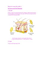
longer. Figure 4-5 shows the voltage and current signature of a charger as the Li-ion cell
passes through stage one and two.
Some chargers claim to fast-charge a Li-ion battery in one hour or less. Such a charger
eliminates stage 2 and goes directly to ‘ready’ once the voltage threshold is reached at the
end of stage 1. The charge level at this point is about 70 percent. The topping charge typically
takes twice as long as the initial charge.
No trickle charge is applied because the Li-ion is unable to absorb overcharge. Trickle charge
could cause plating of metallic lithium, a condition that renders the cell unstable. Instead, a
brief topping charge is applied to compensate for the small amount of self-discharge the
battery and its protective circuit consume.
Depending on the charger and the self-discharge of the battery, a topping charge may be
implemented once every 500 hours or 20 days. Typically, the charge kicks in when the open
terminal voltage drops to 4.05V/cell and turns off when it reaches 4.20V/cell again.
Figure 4-5: Charge stages of a Li-ion battery.
Increasing the charge current on a Li-ion charger does not shorten the charge time by much. Although the voltage
peak is reached quicker with higher current, the topping charge will take longer.
What if a battery is inadvertently overcharged? Li-ion batteries are designed to operate safely
within their normal operating voltage but become increasingly unstable if charged to higher
voltages. On a charge voltage above 4.30V, the cell causes lithium metal plating on the
anode. In addition, the cathode material becomes an oxidizing agent, loses stability and
releases oxygen. Overcharging causes the cell to heat up.
Much attention has been placed on the safety of the Li-ion battery. Commercial Li-ion battery
packs contain a protection circuit that prevents the cell voltage from going too high while
charging. The typical safety threshold is set to 4.30V/cell. In addition, temperature
sensing disconnects the charge if the internal temperature approaches 90°C (194°F). Most
cells feature a mechanical pressure switch that permanently interrupts the current path if a
safe pressure threshold is exceeded. Internal voltage control circuits cut off the battery at low
and high voltage points.
Exceptions are made on some spinel (manganese) packs containing one or two small cells.
On overcharge, this chemistry produces minimal lithium plating on the anode because most
metallic lithium has been removed from the cathode during normal charging. The cathode
material remains stable and does not generate oxygen unless the cell gets extremely hot.
Important: In case of rupture, leaking electrolyte or any other cause of exposure to the
electrolyte, flush with water immediately. If eye exposure occurs, flush with water for
15 minutes and consult a physician immediately.
Charging the Lithium Polymer Battery
The charge process of a Li-Polymer is similar to that of the Li-ion. Li-Polymer uses dry
electrolyte and takes 3 to 5 hours to charge. Li-ion polymer with gelled electrolyte, on the
other hand, is almost identical to that of Li-ion. In fact, the same charge algorithm can be
applied. With most chargers, the user does not need to know whether the battery being
charged is Li-ion or Li-ion polymer.
Almost all commercial batteries sold under the so-called ‘Polymer’ category are a variety of
the Li-ion polymer using some sort of gelled electrolyte. A low-cost dry polymer battery
operating at ambient temperatures is still some years away.
Charging at High and Low Temperatures
Rechargeable batteries can be used under a reasonably wide temperature range. This,
however, does not automatically mean that the batteries can also be charged at these
temperature conditions. While the use of batteries under hot or cold conditions cannot always
be avoided, recharging time is controlled by the user. Efforts should be made to charge the
batteries only at room temperatures.
In general, older battery technologies such as the NiCd are more tolerant to charging at low
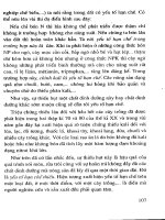
and high temperatures than the more advanced systems. Figure 4-6 indicates the permissible
slow and fast charge temperatures of the NiCd, NiMH, SLA and Li-ion.
Slow Charge (0.1) Fast Charge (0.5-1C)
Nickel Cadmium
0°C to 45°C (32°F to 113°F) 5°C to 45°C (41°F to 113°F)
Nickel-Metal Hydride
0°C to 45°C (32°F to 113°F) 10C° to 45°C (50°F to 113°F)
Lead Acid
0°C to 45°C (32°F to 113°F) 5C° to 45°C (41°F to 113°F)
Lithium Ion
0°C to 45°C (32°F to 113°F) 5C° to 45°C (41°F to 113°F)
Figure 4-6: Permissible temperature limits for various batteries.
Older battery technologies are more tolerant to charging at extreme temperatures than newer, more advanced
systems.
NiCd batteries can be fast-charged in an hour or so, however, such a fast charge can only be
applied within temperatures of 5°C and 45°C (41°F and 113°F). More moderate temperatures
of 10°C to 30°C (50°F to 86°F) produce better results. When charging a NiCd below 5°C
(41°F), the ability to recombine oxygen and hydrogen is greatly reduced and pressure build
up occurs as a result. In some cases, the cells vent, releasing oxygen and hydrogen. Not only
do the escaping gases deplete the electrolyte, hydrogen is highly flammable!
Chargers featuring NDV to terminate full-charge provide some level of protection when fast-
charging at low temperatures. Because of the battery’s poor charge acceptance at low
temperatures, the charge energy is turned into oxygen and to a lesser amount hydrogen. This
reaction causes cell voltage drop, terminating the charge through NDV detection. When this
occurs, the battery may not be fully charged, but venting is avoided or minimized.
To compensate for the slower reaction at temperatures below 5°C, a low charge rate of 0.1C
must be applied. Special charge methods are available for charging at cold temperatures.
Industrial batteries that need to be fast-charged at low temperatures include a thermal blanket
that heats the battery to an acceptable temperature. Among commercial batteries, the NiCd is
the only battery that can accept charge at extremely low temperatures.
Charging at high temperatures reduces the oxygen generation. This reduces the NDV effect
and accurate full-charge detection using this method becomes difficult. To avoid overcharge,
charge termination by temperature measurement becomes more practical.
The charge acceptance of a NiCd at higher temperatures is drastically reduced. A battery that
provides a capacity of 100 percent if charged at moderate room temperature can only accept
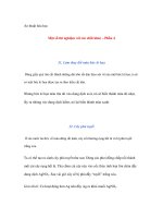
70 percent if charged at 45°C (113°F), and 45 percent if charged at 60°C (140°F) (see
Figure 4-7). Similar conditions apply to the NiMH battery. This demonstrates the typically poor
summer performance of vehicular mounted chargers using nickel-based batteries.
Another reason for poor battery performance, especially if charged at high ambient
temperatures, is premature charge cutoff. This is common with chargers that use absolute
temperature to terminate the fast charge. These chargers read the SoC on battery
temperature alone and are fooled when the room temperature is high. The battery may not be
fully charged, but a timely charge cut-off protects the battery from damage due to excess heat.
The NiMH is less forgiving than the NiCd if charged under high and low temperatures. The
NiMH cannot be fast charged below 10°C (45°F), neither can it be slow charged below 0°C
(32°F). Some industrial chargers adjust the charge rate to prevailing temperatures. Price
sensitivity on consumer chargers does not permit elaborate temperature control features.
Figure 4-7: Effects of temperature on NiCd charge acceptance.
Charge acceptance is much reduced at higher temperatures. NiMH cells follow a similar pattern.
The lead acid battery is reasonably forgiving when it comes to temperature extremes, as in
the case of car batteries. Part of this tolerance is credited to the sluggishness of the lead acid
battery. A full charge under ten hours is difficult, if not impossible. The recommended charge
rate at low temperature is 0.3C.
Figure 4-8 indicates the optimal peak voltage at various temperatures when recharging and
float charging an SLA battery. Implementing temperature compensation on the charger to
adjust to temperature extremes prolongs the battery life by up to 15 percent. This is especially
true when operating at higher temperatures.
An SLA battery should never be allowed to freeze. If this were to occur, the battery would be
permanently damaged and would only provide a few cycles when it returned to normal
temperature.
0°C (32°F) 25°C (77°F) 40°C (104°F)
Voltage limit on recharge
2.55V/cell 2.45V/cell 2.35V/cell
Continuous float voltage
2.35V/cell or lower 2.30V/cell or lower 2.25V/cell or lower
Figure 4-8: Recommended voltage limits on recharge and float charge of SLAs.
These voltage limits should be applied when operating at temperature extremes.
To improve charge acceptance of SLA batteries in colder temperatures, and avoid thermal
runaway in warmer temperatures, the voltage limit of a charger should be compensated by
approximately 3mV per cell per degree Celsius. The voltage adjustment has a negative
coefficient, meaning that the voltage threshold drops as the temperature increases. For
example, if the voltage limit is set to 2.40V/cell at 20°C, the setting should be lowered to
2.37V/cell at 30°C and raised to 2.43V/cell at 10°C. This represents a 30mV correction per
cell per 10 degrees Celsius.
The Li-ion batteries offer good cold and hot temperature charging performance. Some cells
allow charging at 1C from 0°C to 45°C (32°F to 113°F). Most Li-ion cells prefer a lower charge
current when the temperature gets down to 5°C (41°F) or colder. Charging below freezing
must be avoided because plating of lithium metal could occur.
Ultra-fast Chargers
Some charger manufacturers claim amazingly short charge times of 30 minutes or less. With
well-balanced cells and operating at moderate room temperatures, NiCd batteries designed
for fast charging can indeed be charged in a very short time. This is done by simply dumping
in a high charge current during the first 70 percent of the charge cycle. Some NiCd batteries
can take as much a 10C, or ten times the rated current. Precise SoC detection and
temperature monitoring are essential.
The high charge current must be reduced to lower levels in the second phase of the charge
cycle because the efficiency to absorb charge is progressively reduced as the battery moves
to a higher SoC. If the charge current remains too high in the later part of the charge cycle,
the excess energy turns into heat and pressure. Eventually venting occurs, releasing
hydrogen gas. Not only do the escaping gases deplete the electrolyte, they are also highly
flammable!
Several manufacturers offer chargers that claim to fully charge NiCd batteries in half the time
of conventional chargers. Based on pulse charge technology, these chargers intersperse one
or several brief discharge pulses between each charge pulse. This promotes the
recombination of oxygen and hydrogen gases, resulting in reduced pressure buildup and a
lower cell temperature. Ultra-fast-chargers based on this principle can charge a nickel-based
battery in a shorter time than regular chargers, but only to about a 90 percent SoC. A trickle
charge is needed to top the charge to 100 percent.
Pulse chargers are known to reduce the crystalline formation (memory) of nickel-based
batteries. By using these chargers, some improvement in battery performance can be realized,
especially if the battery is affected by memory. The pulse charge method does not replace a
periodic full discharge. For more severe crystalline formation on nickel-based batteries, a full
discharge or recondition cycle is recommended to restore the battery.
Ultra-fast charging can only be applied to healthy batteries and those designed for fast
charging. Some cells are simply not built to carry high current and the conductive path heats
up. The battery contacts also take a beating if the current handling of the spring-loaded
plunger contacts is underrated. Pressing against a flat metal surface, these contacts may
work well at first, and then wear out prematurely. Often, a fine and almost invisible crater
appears on the tip of the contact, which causes a high resistive path or forms an isolator. The
heat generated by a bad contact can melt the plastic.
Another problem with ultra-fast charging is servicing aged batteries that commonly have high
internal resistance. Poor conductivity turns into heat, which further deteriorates the cells.
Battery packs with mismatched cells pose another challenge. The weak cells holding less
capacity are charged before those with higher capacity and start to heat up. This process
makes them vulnerable to further damage.
Many of today’s fast chargers are designed for the ideal battery. Charging less than perfect
specimens can create such a heat buildup that the plastic housing starts to distort. Provisions
must be made to accept special needs batteries, albeit at lower charging speeds.
Temperature sensing is a prerequisite.
The ideal ultra-fast charger first checks the battery type, measures its SoH and then applies a
tolerable charge current. Ultra-high capacity batteries and those that have aged are identified,
and the charge time is prolonged because of higher internal resistance. Such a charger would
provide due respect to those batteries that still perform satisfactorily but are no longer ‘spring
chickens’.
The charger must prevent excessive temperature build-up. Sluggish heat detection, especially
when charging takes place at a very rapid pace, makes it easy to overcharge a battery before
the charge is terminated. This is especially true for chargers that control fast charge using
temperature sensing alone. If the temperature rise is measured right on the skin of the cell,
reasonably accurate SoC detection is possible. If done on the outside surface of the battery
pack, further delays occur. Any prolonged exposure to a temperature of 45°C (113°F) harms
the battery.
New charger concepts are being studied which regulate the charge current according to the
battery's charge acceptance. On the initial charge of an empty battery when the charge
acceptance is high and little gas is generated, a very high charge current can be applied.
Towards the end of a charge, the current is tapered down.
Charge IC Chips
Newer battery systems demand more complex chargers than batteries with older chemistries.
With today’s charge IC chips, designing a charger has been simplified. These chips apply
proven charge algorithms and are capable of servicing all major battery chemistries. As the
price of these chips decreases, design engineers make more use of this product. With the
charge IC chip, an engineer can focus entirely on the portable equipment rather than devoting
time to developing a charging circuit.
The charge IC chips have some limitations, however. The charge algorithm is fixed and does
not allow fine-tuning. If a trickle charge is needed to raise a Li-ion that has dropped below
2.5V/cell to its normal operating voltage, the charge IC may not be able to perform this
function. Similarly, if an ultra-fast charge is needed for nickel-based batteries, the charge IC
applies a fixed charge current and does not take into account the SoH of the battery.
Furthermore, a temperature compensated charge would be difficult to administer if the IC
chips do not provide this feature.
Using a small micro controller is an alternative to selecting an off-the-shelf charge IC. The
hardware cost is about the same. When opting for the micro controller, custom firmware will
be needed. Some extra features can be added with little extra cost. They are fast charging
based on the SoH of the battery. Ambient temperatures can also be taken into account.
Whether an IC chip or micro controller is used, peripheral components are required consisting
of solid-state switches and a power supply.
Chapter 5: Discharge Methods
The purpose of a battery is to store energy and release it at the appropriate time in a
controlled manner. Being capable of storing a large amount of energy is one thing; the ability
to satisfy the load demands is another. The third criterion is being able to deliver all available
energy without leaving precious energy behind when the equipment cuts off.
In this chapter, we examine how different discharge methods can affect the deliverance of
power. Further, we look at the load requirements of various portable devices and evaluate the
performance of each battery chemistry in terms of discharge.
C-rate
The charge and discharge current of a battery is measured in C-rate. Most portable batteries,
with the exception of the lead acid, are rated at 1C. A discharge of 1C draws a current equal
to the rated capacity. For example, a battery rated at 1000mAh provides 1000mA for one hour
if discharged at 1C rate. The same battery discharged at 0.5C provides 500mA for two hours.
At 2C, the same battery delivers 2000mA for 30 minutes. 1C is often referred to as a one-hour
discharge; a 0.5C would be a two-hour, and a 0.1C a 10 hour discharge.
The capacity of a battery is commonly measured with a battery analyzer. If the analyzer’s
capacity readout is displayed in percentage of the nominal rating, 100 percent is shown if
1000mA can be drawn for one hour from a battery that is rated at 1000mAh. If the battery only
lasts for 30 minutes before cut-off, 50 percent is indicated. A new battery sometimes provides
more than 100 percent capacity. In such a case, the battery is conservatively rated and can
endure a longer discharge time than specified by the manufacturer.
When discharging a battery with a battery analyzer that allows setting different discharge C-
rates, a higher capacity reading is observed if the battery is discharged at a lower C-rate and
vice versa. By discharging the 1000mAh battery at 2C, or 2000mA, the analyzer is scaled to
derive the full capacity in 30 minutes. Theoretically, the capacity reading should be the same
as a slower discharge, since the identical amount of energy is dispensed, only over a shorter
time. Due to energy loss that occurs inside the battery and a drop in voltage that causes the
battery to reach the low-end voltage cut-off sooner, the capacity reading is lower and may be
97 percent. Discharging the same battery at 0.5C, or 500mA over two hours would increase
the capacity reading to about 103 percent.
The discrepancy in capacity readings with different C-rates largely depends on the internal
resistance of the battery. On a new battery with a good load current characteristic or low
internal resistance, the difference in the readings is only a few percentage points. On a
battery exhibiting high internal resistance, the difference in capacity readings could swing
plus/minus 10 percent or more.
One battery that does not perform well at a 1C discharge rate is the SLA. To obtain a practical
capacity reading, manufacturers commonly rate these batteries at 0.05C or 20 hour discharge.
Even at this slow discharge rate, it is often difficult to attain 100 percent capacity. By
discharging the SLA at a more practical 5h discharge (0.2C), the capacity readings are
correspondingly lower. To compensate for the different readings at various discharge currents,
manufacturers offer a capacity offset.
Applying the capacity offset does not improve battery performance; it merely adjusts the
capacity calculation if discharged at a higher or lower C-rate than specified. The battery
manufacturer determines the amount of capacity offset recommended for a given battery type.
Li-ion/polymer batteries are electronically protected against high discharge currents.
Depending on battery type, the discharge current is limited somewhere between 1C and 2C.
This protection makes the Li-ion unsuitable for biomedical equipment, power tools and high-
wattage transceivers. These applications are commonly reserved for the NiCd battery.
Depth of Discharge
The typical end-of-discharge voltage for nickel-based batteries is 1V/cell. At that voltage level,
about 99 percent of the energy is spent and the voltage starts to drop rapidly if the discharge
continues. Discharging beyond the cut-off voltage must be avoided, especially under
heavy load.
Since the cells in a battery pack cannot be perfectly matched, a negative voltage potential
(cell reversal) across a weaker cell occurs if the discharge is allowed to continue beyond the
cut-off point. The larger the number of cells connected in series, the greater the likelihood of
this occurring.
A NiCd battery can tolerate a limited amount of cell reversal, which is typically about 0.2V.
During that time, the polarity of the positive electrode is reversed. Such a condition can only
be sustained for a brief moment because hydrogen evolution occurs on the positive electrode.
This leads to pressure build-up and cell venting.
If the cell is pushed further into voltage reversal, the polarity of both electrodes is being
reversed, resulting in an electrical short. Such a fault cannot be corrected and the pack will
need to be replaced.
On battery analyzers that apply a secondary discharge (recondition), the current is controlled
to assure that the maximum allowable current, while in sub-discharge range, does not exceed
a safe limit. Should a cell reversal develop, the current would be low enough as not to cause
damage. A cell breakdown through recondition is possible on a weak or aged pack.
If the battery is discharged at a rate higher than 1C, the more common end-of-discharge point
of a nickel-based battery is 0.9V/cell. This is done to compensate for the voltage drop induced
by the internal resistance of the cell, the wiring, protection devices and contacts of the pack. A
lower cut-off point also delivers better battery performance at cold temperatures.
The recommended end-of-discharge voltage for the SLA is 1.75V/cell. Unlike the preferred
flat discharge curve of the NiCd, the SLA has a gradual voltage drop with a rapid drop
towards the end of discharge (see Figure 5-1). Although this steady decrease in voltage is a
disadvantage, it has a benefit because the voltage level can be utilized to display the state-of-
charge (SoC) of a battery. However, the voltage readings fluctuate with load and the SoC
readings are inaccurate.
Figure 5-1: Discharge characteristics of NiCd, NiMH and SLA batteries.
While voltage readings to measure the SoC are not practical on nickel-based batteries, the SLA enables some level
of indication as to the SoC.
°C (77°F) with respect to the depth of discharge is:
• 150 – 200 cycles with 100 percent depth of discharge (full discharge)
• 400 – 500 cycles with 50 percent depth of discharge (partial discharge)
• 1000 and more cycles with 30 percent depth of discharge (shallow discharge)
The SLA should not be discharged beyond 1.75V per cell, nor can it be stored in a discharged
state. The cells of a discharged SLA sulfate, a condition that renders the battery useless if left
in that state for a few days.
The Li-ion typically discharges to 3.0V/cell. The spinel and coke versions can be discharged
to 2.5V/cell. The lower end-of-discharge voltage gains a few extra percentage points. Since
the equipment manufacturers cannot specify which battery type may be used, most
equipment is designed for a three-volt cut-off.
Caution should be exercised not to discharge a lithium-based battery too low. Discharging a
lithium-based battery below 2.5V may cut off the battery’s protection circuit. Not all chargers
accommodate a recharge on batteries that have gone to sleep because of low voltage.
Some Li-ion batteries feature an ultra-low voltage cut-off that permanently disconnects the
pack if a cell dips below 1.5V. This precaution prohibits recharge if a battery has dwelled in an
illegal voltage state. A very deep discharge may cause the formation of copper shunt, which
can lead to a partial or total electrical short. The same occurs if the cell is driven into negative
polarity and is kept in that state for a while. A fully discharged battery should be charged at
0.1C. Charging a battery with a copper shunt at the 1C rate would cause excessive heat.
Such a battery should be removed from service.
Discharging a battery too deeply is one problem; equipment that cuts off before the energy is
consumed is another. Some portable devices are not properly tuned to harvest the optimal
energy stored in a battery. Valuable energy may be left behind if the voltage cut-off-point is
set too high.
Digital devices are especially demanding on a battery. Momentary pulsed loads cause a brief
voltage drop, which may push the voltage into the cut-off region. Batteries with high internal
resistance are particularly vulnerable to premature cut-off. If such a battery is removed from
the equipment and discharged to the appropriate cut-off point with a battery analyzer on DC
load, a high level of residual capacity can still be obtained.
Most rechargeable batteries prefer a partial rather than a full discharge. Repeated full
discharge robs the battery of its capacity. The battery chemistry which is most affected by
repeat deep discharge is lead acid. Additives to the deep-cycle version of the lead acid
battery compensate for some of the cycling strain.
Similar to the lead acid battery, the Li-ion battery prefers shallow over repetitive deep
discharge cycles. Up to 1000 cycles can be achieved if the battery is only partially discharged.
Besides cycling, the performance of the Li-ion is also affected by aging. Capacity loss through
aging is independent of use. However, in daily use, there is a combination of both.
The NiCd battery is least affected by repeated full discharge cycles. Several thousand
charge/discharge cycles can be obtained with this battery system. This is the reason why the
NiCd performs well on power tools and two-way radios that are in constant use. The NiMH is
more delicate with respect to repeated deep cycling.
Pulse Discharge
Battery chemistries react differently to specific loading requirements. Discharge loads range
from a low and steady current used in a flashlight, to intermittent high current bursts in a
power tool, to sharp current pulses required for digital communications equipment, to a
prolonged high current load for an electric vehicle traveling at highway speed. Because
batteries are chemical devices that must convert higher-level active materials into an alternate
state during discharge, the speed of such transaction determines the load characteristics of a
battery. Also referred to as concentration polarization, the nickel and lithium-based batteries
are superior to lead-based batteries in reaction speed. This reflects in good load
characteristics.
The lead acid battery performs best at a slow 20-hour discharge. A pulse discharge also
works well because the rest periods between the pulses help to disperse the depleted acid
concentrations back into the electrode plate. In terms of capacity, these two discharge
methods provide the highest efficiency for this battery chemistry.
A discharge at the rated capacity of 1C yields the poorest efficiency for the lead acid battery.
The lower level of conversion, or increased polarization, manifests itself in a momentary
higher internal resistance due to the depletion of active material in the reaction.
Different discharge methods, notably pulse discharging, also affect the longevity of some
battery chemistries. While NiCd and Li-ion are robust and show minimal deterioration when
pulse discharged, the NiMH exhibits a reduced cycle life when powering a digital load.
In a recent study, the longevity of NiMH was observed by discharging these batteries with
analog and digital loads. In both tests, the battery discharged to 1.04V/cell. The analog
discharge current was 500mA; the digital mode simulated the load requirements of the Global
System for Mobile Communications (GSM) protocol and applied 1.65-ampere peak current for
12 ms every 100 ms. The current in between the peaks was 270mA. (Note that the GSM
pulse for voice is about 550 ms every 4.5 ms).
With the analog discharge, the NiMH wore out gradually, providing an above average service
life. At 700 cycles, the battery still provided 80 percent capacity. By contrast, the cells faded
more rapidly with a digital discharge. The 80 percent capacity threshold was reached after
only 300 cycles. This phenomenon indicates that the kinetic characteristics for the NiMH
deteriorate more rapidly with a digital rather than an analog load.
Discharging at High and Low Temperature
Batteries function best at room temperature. Operating batteries at an elevated temperature
dramatically shortens their life. Although a lead acid battery may deliver the highest capacity
at temperatures above 30°C (86°F), prolonged use under such conditions decreases the life
of the battery.
Similarly, a Li-ion performs better at high temperatures. Elevated temperatures temporarily
counteracts the battery’s internal resistance, which is a result of aging. The energy gain is
short-lived because elevated temperature promotes aging by further increasing the internal
resistance.
There is one exception to running a battery at high temperature — it is the lithium polymer
with dry solid polymer electrolyte, the true ‘plastic battery’. While the commercial Li-ion
polymer uses some moist electrolyte to enhance conductivity, the dry solid polymer version
depends on heat to enable ion flow. This requires that the battery core be kept at an operation
temperature of 60°C to 100°C.
The dry solid polymer battery has found a niche market as backup power in warm climates.
The battery is kept at the operating temperature with built-in heating elements. During normal
operation, the core is kept warm with power derived from the utility grid. Only on a power
outage would the battery need to provide power to maintain its own heat. To minimize heat
loss, the battery is insulated.
The Li-ion polymer as standby battery is said to outperform VRLA batteries in terms of size
and longevity, especially in shelters in which the temperature cannot be controlled. The high
price of the Li-ion polymer battery remains an obstacle.
The NiMH chemistry degrades rapidly if cycled at higher ambient temperatures. Optimum
battery life and cycle count are achieved at 20°C (68°F). Repeated charging and discharging
at higher temperatures will cause irreversible capacity loss. For example, if operated at 30°C
(86°F), the cycle life is reduced by 20 percent. At 40°C (104°F), the loss jumps to a whopping
40 percent. If charged and discharged at 45°C (113°F), the cycle life is only half of what can
be expected if used at moderate room temperature. The NiCd is also affected by high
temperature operation, but to a lesser degree.
At low temperatures, the performance of all battery chemistries drops drastically. While -20°C
(-4°F) is threshold at which the NiMH, SLA and Li-ion battery stop functioning, the NiCd can
go down to -40°C (-40°F). At that frigid temperature, the NiCd is limited to a discharge rate of
0.2C (5 hour rate). There are new types of Li-ion batteries that are said to operate down to -
40°C.
It is important to remember that although a battery may be capable of operating at cold
temperatures, this does not automatically mean it can also be charged under those conditions.
The charge acceptance for most batteries at very low temperatures is extremely confined.
Most batteries need to be brought up to temperatures above the freezing point for charging.
The NiCd can be recharged at below freezing provided the charge rate is reduced to 0.1C.
Part Two
You and the Battery
Chapter 6: The Secrets of Battery Runtime
Is the runtime of a portable device directly related to the size of the battery and the energy it
can hold? In most cases, the answer is yes. But with digital equipment, the length of time a
battery can operate is not necessarily linear to the amount of energy stored in the battery.
In this chapter we examine why the specified runtime of a portable device cannot always be
achieved, especially after the battery has aged. We address the four renegades that are
affecting the performance of the battery. They are: declining capacity, increasing internal
resistance, elevated self-discharge, and premature voltage cut-off on discharge.
Declining Capacity
The amount of charge a battery can hold gradually decreases due to usage, aging and, with
some chemistries, lack of maintenance. Specified to deliver about 100 percent capacity when
new, the battery eventually requires replacement when the capacity drops to the 70 or
60 percent level. The warranty threshold is typically 80 percent.
The energy storage of a battery can be divided into three imaginary sections consisting of
available energy, the empty zone that can be refilled and the rock content that has become
unusable. Figure 6-1 illustrates these three sections of a battery.
In nickel-based batteries, the rock content may be in the form of crystalline formation, also
known as memory. Deep cycling can often restore the capacity to full service. Also known as
‘exercise’, a typical cycle consists of one or several discharges to 1V/cell with subsequent
discharges.
Figure 6-1: Battery charge capacity.
Three imaginary sections of a battery consisting of available
energy, empty zone and rock content.
With usage and age, the rock content grows. Without regular
maintenance, the user may end up carrying rocks instead of
batteries.
The loss of charge acceptance of the Li-ion/polymer batteries is due to cell oxidation, which
occurs naturally during use and as part of aging. Li-ion batteries cannot be restored with
cycling or any other external means. The capacity loss is permanent because the metals used
in the cells are designated to run for a specific time only and are being consumed during their
service life.
Performance degradation of the lead acid battery is often caused by sulfation, a thin layer that
forms on the negative cell plates, which inhibits current flow. In addition, there is grid
corrosion that sets in on the positive plate. With sealed lead acid batteries, the issue of water
permeation, or loss of electrolyte, also comes into play. Sulfation can be reversed to a certain
point with cycling and/or topping charge but corrosion and permeation are permanent. Adding
water to a sealed lead acid battery may help to restore operation but the long-term results are
unpredictable.
Increasing Internal Resistance
To a large extent, the internal resistance, also known as impedance, determines the
performance and runtime of a battery. If measured with an AC signal, the internal resistance
of a battery is also referred to as impedance. High internal resistance curtails the flow of
energy from the battery to the equipment.
A battery with simulated low and high internal resistance is illustrated below. While a battery
with low internal resistance can deliver high current on demand, a battery with high resistance
collapses with heavy current. Although the battery may hold sufficient capacity, the voltage
drops to the cut-off line and the ‘low battery’ indicator is triggered. The equipment stops
functioning and the remaining energy is undelivered.
Figure 6-2: Effects of impedance on
battery load.
A
battery with low impedance provides
unrestricted current flow and delivers all
available energy. A battery with high impedance
cannot deliver high-energy bursts due to a
restricted path, and equipment may cut off
prematurely.
NiCd has the lowest internal resistance of all commercial battery systems, even after
delivering 1000 cycles. In comparison, NiMH starts with a slightly higher resistance and the
readings increase rapidly after 300 to 400 cycles.
Maintaining a battery at low internal resistance is important, especially with digital devices that
require high surge current. Lack of maintenance on nickel-based batteries can increase the
internal resistance. Readings of more than twice the normal resistance have been observed
on neglected NiCd batteries. After applying a recondition cycle with the Cadex 7000 Series
battery analyzer, the readings on the batteries returned to normal. Reconditioning clears the
cell plates of unwanted crystalline formations, which restores proper current flow.
Li-ion offers internal resistance characteristics that are between those of NiMH and NiCd.
Usage does not contribute much to the increase in resistance, but aging does. The typical life
span of a Li-ion battery is two to three years, whether it is used or not. Cool storage and
keeping the battery in a partially charged state when not in use retard the aging process.
The internal resistance of the Li-ion batteries cannot be improved with cycling. The cell
oxidation, which causes high resistance, is non-reversible. The ultimate cause of failure is
high internal resistance. Energy may still be present in the battery, but it can no longer be
delivered due to poor conductivity.