Computer organization and design Design 2nd phần 8 pot
Bạn đang xem bản rút gọn của tài liệu. Xem và tải ngay bản đầy đủ của tài liệu tại đây (275.45 KB, 91 trang )
648
Chapter 8 Multiprocessors
workloads with operating systems included. Other major classes of workloads
are databases, fileservers, and transaction processing systems. Constructing real-
istic versions of such workloads and accurately measuring them on multiproces-
sors, including any OS activity, is an extremely complex and demanding process,
at the edge of what we can do with performance modeling tools. Future editions
of this book may contain characterizations of such workloads. Happily, there is
some evidence that the parallel processing and memory system behaviors of data-
base and transaction processing workloads are similar to those of large multipro-
grammed workloads, which include the OS activity. For the present, we have to
be content with examining such a multiprogramming workload.
Parallel Applications
Our parallel applications workload consists of two applications and two compu-
tational kernels. The kernels are an FFT (fast Fourier transformation) and an LU
decomposition, which were chosen because they represent commonly used tech-
niques in a wide variety of applications and have performance characteristics typ-
ical of many parallel scientific applications. In addition, the kernels have small
code segments whose behavior we can understand and directly track to specific
architectural characteristics.
The two applications that we use in this chapter are Barnes and Ocean, which
represent two important but very different types of parallel computation. We
briefly describe each of these applications and kernels and characterize their ba-
sic behavior in terms of parallelism and communication. We describe how the
problem is decomposed for a distributed shared-memory machine; certain data
decompositions that we describe are not necessary on machines that have a single
centralized memory.
The FFT Kernel
The
fast Fourier transform
(FFT) is the key kernel in applications that use spec-
tral methods, which arise in fields ranging from signal processing to fluid flow to
climate modeling. The FFT application we study here is a one-dimensional ver-
sion of a parallel algorithm for a complex-number FFT. It has a sequential execu-
tion time for
n
data points of
n
log
n
. The algorithm uses a high radix (equal to
) that minimizes communication. The measurements shown in this chapter are
collected for a million-point input data set.
There are three primary data structures: the input and output arrays of the data
being transformed and the roots of unity matrix, which is precomputed and only
read during the execution. All arrays are organized as square matrices. The six
steps in the algorithm are as follows:
1. Transpose data matrix.
2. Perform 1D FFT on each row of data matrix.
n
8.2 Characteristics of Application Domains
649
3. Multiply the roots of unity matrix by the data matrix and write the result in the
data matrix.
4. Transpose data matrix.
5. Perform 1D FFT on each row of data matrix.
6. Transpose data matrix.
The data matrices and the roots of unity matrix are partitioned among proces-
sors in contiguous chunks of rows, so that each processor’s partition falls in its
own local memory. The first row of the roots of unity matrix is accessed heavily
by all processors and is often replicated, as we do, during the first step of the al-
gorithm just shown.
The only communication is in the transpose phases, which require all-to-all
communication of large amounts of data. Contiguous subcolumns in the rows as-
signed to a processor are grouped into blocks, which are transposed and placed
into the proper location of the destination matrix. Every processor transposes one
block locally and sends one block to each of the other processors in the system.
Although there is no reuse of individual words in the transpose, with long cache
blocks it makes sense to block the transpose to take advantage of the spatial
locality afforded by long blocks in the source matrix.
The LU Kernel
LU is an LU factorization of a dense matrix and is representative of many dense
linear algebra computations, such as QR factorization, Cholesky factorization,
and eigenvalue methods. For a matrix of size
n
×
n
the running time is
n
3
and the
parallelism is proportional to
n
2
. Dense LU factorization can be performed effi-
ciently by blocking the algorithm, using the techniques in Chapter 5, which leads
to highly efficient cache behavior and low communication. After blocking the al-
gorithm, the dominant computation is a dense matrix multiply that occurs in the
innermost loop. The block size is chosen to be small enough to keep the cache
miss rate low, and large enough to reduce the time spent in the less parallel parts
of the computation. Relatively small block sizes (8
×
8 or 16 × 16) tend to satisfy
both criteria. Two details are important for reducing interprocessor communica-
tion. First, the blocks of the matrix are assigned to processors using a 2D tiling:
the (where each block is B × B) matrix of blocks is allocated by laying a
grid of size over the matrix of blocks in a cookie-cutter fashion until all the
blocks are allocated to a processor. Second, the dense matrix multiplication is
performed by the processor that owns the destination block. With this blocking
and allocation scheme, communication during the reduction is both regular and
predictable. For the measurements in this chapter, the input is a 512 × 512 matrix
and a block of 16 × 16 is used.
A natural way to code the blocked LU factorization of a 2D matrix in a shared
address space is to use a 2D array to represent the matrix. Because blocks are
n
B
n
B
×
pp×
650 Chapter 8 Multiprocessors
allocated in a tiled decomposition, and a block is not contiguous in the address
space in a 2D array, it is very difficult to allocate blocks in the local memories of
the processors that own them. The solution is to ensure that blocks assigned to a
processor are allocated locally and contiguously by using a 4D array (with the
first two dimensions specifying the block number in the 2D grid of blocks, and
the next two specifying the element in the block).
The Barnes Application
Barnes is an implementation of the Barnes-Hut n-body algorithm solving a
problem in galaxy evolution. N-body algorithms simulate the interaction among
a large number of bodies that have forces interacting among them. In this in-
stance the bodies represent collections of stars and the force is gravity. To reduce
the computational time required to model completely all the individual inter-
actions among the bodies, which grow as n
2
, n-body algorithms take advantage
of the fact that the forces drop off with distance. (Gravity, for example, drops off
as 1/d
2
, where d is the distance between the two bodies.) The Barnes-Hut algo-
rithm takes advantage of this property by treating a collection of bodies that are
“far away” from another body as a single point at the center of mass of the collec-
tion and with mass equal to the collection. If the body is far enough from any
body in the collection, then the error introduced will be negligible. The collec-
tions are structured in a hierarchical fashion, which can be represented in a tree.
This algorithm yields an n log n running time with parallelism proportional to n.
The Barnes-Hut algorithm uses an octree (each node has up to eight children)
to represent the eight cubes in a portion of space. Each node then represents the
collection of bodies in the subtree rooted at that node, which we call a cell. Be-
cause the density of space varies and the leaves represent individual bodies, the
depth of the tree varies. The tree is traversed once per body to compute the net
force acting on that body. The force-calculation algorithm for a body starts at the
root of the tree. For every node in the tree it visits, the algorithm determines if the
center of mass of the cell represented by the subtree rooted at the node is “far
enough away” from the body. If so, the entire subtree under that node is approxi-
mated by a single point at the center of mass of the cell, and the force this center
of mass exerts on the body is computed. On the other hand, if the center of mass
is not far enough away, the cell must be “opened” and each of its subtrees visited.
The distance between the body and the cell, together with the error tolerances,
determines which cells must be opened. This force calculation phase dominates
the execution time. This chapter takes measurements using 16K bodies; the crite-
rion for determining whether a cell needs to be opened is set to the middle of the
range typically used in practice.
Obtaining effective parallel performance on Barnes-Hut is challenging be-
cause the distribution of bodies is nonuniform and changes over time, making
partitioning the work among the processors and maintenance of good locality of
8.2 Characteristics of Application Domains 651
reference difficult. We are helped by two properties: the system evolves slowly;
and because gravitational forces fall off quickly, with high probability, each cell
requires touching a small number of other cells, most of which were used on the
last time step. The tree can be partitioned by allocating each processor a subtree.
Many of the accesses needed to compute the force on a body in the subtree will
be to other bodies in the subtree. Since the amount of work associated with a sub-
tree varies (cells in dense portions of space will need to access more cells), the
size of the subtree allocated to a processor is based on some measure of the work
it has to do (e.g., how many other cells does it need to visit), rather than just on
the number of nodes in the subtree. By partitioning the octree representation, we
can obtain good load balance and good locality of reference, while keeping the
partitioning cost low. Although this partitioning scheme results in good locality
of reference, the resulting data references tend to be for small amounts of data
and are unstructured. Thus this scheme requires an efficient implementation of
shared-memory communication.
The Ocean Application
Ocean simulates the influence of eddy and boundary currents on large-scale flow
in the ocean. It uses a restricted red-black Gauss-Seidel multigrid technique to
solve a set of elliptical partial differential equations. Red-black Gauss-Seidel is
an iteration technique that colors the points in the grid so as to consistently up-
date each point based on previous values of the adjacent neighbors. Multigrid
methods solve finite difference equations by iteration using hierarchical grids.
Each grid in the hierarchy has fewer points than the grid below, and is an approx-
imation to the lower grid. A finer grid increases accuracy and thus the rate of con-
vergence, while requiring more execution time, since it has more data points.
Whether to move up or down in the hierarchy of grids used for the next iteration
is determined by the rate of change of the data values. The estimate of the error at
every time-step is used to decide whether to stay at the same grid, move to a
coarser grid, or move to a finer grid. When the iteration converges at the finest
level, a solution has been reached. Each iteration has n
2
work for an n × n grid
and the same amount of parallelism.
The arrays representing each grid are dynamically allocated and sized to the
particular problem. The entire ocean basin is partitioned into square subgrids (as
close as possible) that are allocated in the portion of the address space corre-
sponding to the local memory of the individual processors, which are assigned
responsibility for the subgrid. For the measurements in this chapter we use an in-
put that has 130 × 130 grid points. There are five steps in a time iteration. Since
data are exchanged between the steps, all the processors present synchronize at
the end of each step before proceeding to the next. Communication occurs when
the boundary points of a subgrid are accessed by the adjacent subgrid in nearest-
neighbor fashion.
652 Chapter 8 Multiprocessors
Computation/Communication for the Parallel Programs
A key characteristic in determining the performance of parallel programs is the
ratio of computation to communication. If the ratio is high, it means the applica-
tion has lots of computation for each datum communicated. As we saw in section
8.1, communication is the costly part of parallel computing; therefore high com-
putation-to-communication ratios are very beneficial. In a parallel processing
environment, we are concerned with how the ratio of computation to communica-
tion changes as we increase either the number of processors, the size of the prob-
lem, or both. Knowing how the ratio changes as we increase the processor count
sheds light on how well the application can be sped up. Because we are often in-
terested in running larger problems, it is vital to understand how changing the
data set size affects this ratio.
To understand what happens quantitatively to the computation-to-communica-
tion ratio as we add processors, consider what happens separately to computation
and to communication as we either add processors or increase problem size. For
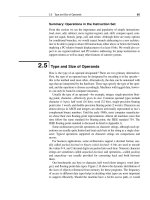
these applications Figure 8.4 shows that as we add processors, the amount of
computation per processor falls proportionately and the amount of communica-
tion per processor falls more slowly. As we increase the problem size, the compu-
tation scales as the O( ) complexity of the algorithm dictates. Communication
scaling is more complex and depends on details of the algorithm; we describe the
basic phenomena for each application in the caption of Figure 8.4.
The overall computation-to-communication ratio is computed from the indi-
vidual growth rate in computation and communication. In general, this rate rises
slowly with an increase in data set size and decreases as we add processors. This
reminds us that performing a fixed-size problem with more processors leads to
increasing inefficiencies because the amount of communication among proces-
sors grows. It also tells us how quickly we must scale data set size as we add pro-
cessors, to keep the fraction of time in communication fixed.
Multiprogramming and OS Workload
For small-scale multiprocessors we will also look at a multiprogrammed work-
load consisting of both user activity and OS activity. The workload used is two
independent copies of the compile phase of the Andrew benchmark. The compile
phase consists of a parallel make using eight processors. The workload runs for
5.24 seconds on eight processors, creating 203 processes and performing 787
disk requests on three different file systems. The workload is run with 128 MB of
memory, and no paging activity takes place.
The workload has three distinct phases: compiling the benchmarks, which in-
volves substantial compute activity; installing the object files in a library; and re-
moving the object files. The last phase is completely dominated by I/O and only
two processes are active (one for each of the runs). In the middle phase, I/O also
plays a major role and the processes are largely idle.
8.2 Characteristics of Application Domains 653
Because both idle time and instruction cache performance are important in
this workload, we examine these two issues here, focusing on the data cache per-
formance later in the chapter. For the workload measurements, we assume the
following memory and I/O systems:
Application
Scaling of
computation
Scaling of
communication
Scaling of computation-
to-communication
FFT
LU
Barnes
Approximately Approximately
Ocean
FIGURE 8.4 Scaling of computation, of communication, and of the ratio are critical
factors in determining performance on parallel machines. In this table
p
is the increased
processor count and
n
is the increased data set size. Scaling is on a per-processor basis. The
computation scales up with
n
at the rate given by O( ) analysis and scales down linearly as
p
is increased. Communication scaling is more complex. In FFT all data points must interact,
so communication increases with
n
and decreases with
p.
In LU and Ocean, communication
is proportional to the boundary of a block, so it scales with data set size at a rate proportional
to the side of a square with
n
points, namely ; for the same reason communication in these
two applications scales inversely to
. Barnes has the most complex scaling properties.
Because of the fall-off of interaction between bodies, the basic number of interactions among
bodies, which require communication, scales as . An additional factor of log n is needed
to maintain the relationships among the bodies. As processor count is increased, communi-
cation scales inversely to .
I/O system Memory
Level 1 instruction cache 32K bytes, two-way set associative with a 64-byte block,
one clock cycle hit time
Level 1 data cache 32K bytes, two-way set associative with a 32-byte block,
one clock cycle hit time
Level 2 cache 1M bytes unified, two-way set associative with a 128-byte
block, hit time 10 clock cycles
Main memory Single memory on a bus with an access time of 100 clock
cycles
Disk system Fixed access latency of 3 ms (less than normal to reduce
idle time)
nnlog
p
n
p
nlog
n
p
n
p
n
p
nnlog
p
nnlog()
p
n
p
n
p
n
p
n
p
n
p
n
p
654 Chapter 8 Multiprocessors
Figure 8.5 shows how the execution time breaks down for the eight processors
using the parameters just listed. Execution time is broken into four components:
idle—execution in the kernel mode idle loop; user—execution in user code; syn-
chronization—execution or waiting for synchronization variables; and kernel—
execution in the OS that is neither idle nor in synchronization access.
Unlike the parallel scientific workload, this multiprogramming workload has a
significant instruction cache performance loss, at least for the OS. The instruction
cache miss rate in the OS for a 32-byte block size, two set-associative cache varies
from 1.7% for a 32-KB cache to 0.2% for a 256-KB cache. User-level, instruction
cache misses are roughly one-sixth of the OS rate, across the variety of cache sizes.
Multis are a new class of computers based on multiple microprocessors. The small
size, low cost, and high performance of microprocessors allow design and con-
struction of computer structures that offer significant advantages in manufacture,
price-performance ratio, and reliability over traditional computer families.
Multis are likely to be the basis for the next, the fifth, generation of computers.
[p. 463]
Bell [1985]
As we saw in Chapter 5, the use of large, multilevel caches can substantially re-
duce the memory bandwidth demands of a processor. If the main memory band-
width demands of a single processor are reduced, multiple processors may be
able to share the same memory. Starting in the 1980s, this observation, combined
with the emerging dominance of the microprocessor, motivated many designers
to create small-scale multiprocessors where several processors shared a single
Mode % instructions executed % execution time
Idle 69% 64%
User 27% 27%
Sync 1% 2%
Kernel 3% 7%
FIGURE 8.5 The distribution of execution time in the multiprogrammed parallel make
workload. The high fraction of idle time is due to disk latency when only one of the eight pro-
cesses is active. These data and the subsequent measurements for this workload were col-
lected with the SimOS system [Rosenblum 1995]. The actual runs and data collection were
done by M. Rosenblum, S. Herrod, and E. Bugnion of Stanford University, using the SimOS
simulation system.
8.3
Centralized Shared-Memory Architectures
8.3 Centralized Shared-Memory Architectures 655
physical memory connected by a shared bus. Because of the small size of the pro-
cessors and the significant reduction in the requirements for bus bandwidth
achieved by large caches, such machines are extremely cost-effective, provided
that a sufficient amount of memory bandwidth exists. Early designs of such ma-
chines were able to place an entire CPU and cache subsystem on a board, which
plugged into the bus backplane. More recent designs have placed up to four pro-
cessors per board; and by some time early in the next century, there may be mul-
tiple processors on a single die configured as a multiprocessor. Figure 8.1 on
page 638 shows a simple diagram of such a machine.
The architecture supports the caching of both shared and private data. Private
data is used by a single processor, while shared data is used by multiple proces-
sors, essentially providing communication among the processors through reads
and writes of the shared data. When a private item is cached, its location is mi-
grated to the cache, reducing the average access time as well as the memory
bandwidth required. Since no other processor uses the data, the program behavior
is identical to that in a uniprocessor. When shared data are cached, the shared
value may be replicated in multiple caches. In addition to the reduction in access
latency and required memory bandwidth, this replication also provides a reduc-
tion in contention that may exist for shared data items that are being read by mul-
tiple processors simultaneously. Caching of shared data, however, introduces a
new problem: cache coherence.
What Is Multiprocessor Cache Coherence?
As we saw in Chapter 6, the introduction of caches caused a coherence problem
for I/O operations, since the view of memory through the cache could be different
from the view of memory obtained through the I/O subsystem. The same problem
exists in the case of multiprocessors, because the view of memory held by two dif-
ferent processors is through their individual caches. Figure 8.6 illustrates the prob-
lem and shows how two different processors can have two different values for the
same location. This is generally referred to as the cache-coherence problem.
Time Event
Cache
contents
for CPU A
Cache
contents for
CPU B
Memory
contents for
location X
01
1 CPU A reads X 1 1
2 CPU B reads X 1 1 1
3 CPU A stores 0 into X 0 1 0
FIGURE 8.6 The cache-coherence problem for a single memory location (X), read and
written by two processors (A and B). We initially assume that neither cache contains the
variable and that X has the value 1. We also assume a write-through cache; a write-back
cache adds some additional but similar complications. After the value of X has been written
by A, A’s cache and the memory both contain the new value, but B’s cache does not, and if
B reads the value of X, it will receive 1!
656 Chapter 8 Multiprocessors
Informally, we could say that a memory system is coherent if any read of a
data item returns the most recently written value of that data item. This definition,
while intuitively appealing, is vague and simplistic; the reality is much more
complex. This simple definition contains two different aspects of memory system
behavior, both of which are critical to writing correct shared-memory programs.
The first aspect, called coherence, defines what values can be returned by a read.
The second aspect, called consistency, determines when a written value will be
returned by a read. Let’s look at coherence first.
A memory system is coherent if
1. A read by a processor, P, to a location X that follows a write by P to X, with
no writes of X by another processor occurring between the write and the read
by P, always returns the value written by P.
2. A read by a processor to location X that follows a write by another processor
to X returns the written value if the read and write are sufficiently separated
and no other writes to X occur between the two accesses.
3. Writes to the same location are serialized: that is, two writes to the same loca-
tion by any two processors are seen in the same order by all processors. For
example, if the values 1 and then 2 are written to a location, processors can
never read the value of the location as 2 and then later read it as 1.
The first property simply preserves program order—we expect this property to be
true even in uniprocessors. The second property defines the notion of what it
means to have a coherent view of memory: If a processor could continuously
read an old data value, we would clearly say that memory was incoherent.
The need for write serialization is more subtle, but equally important. Suppose
we did not serialize writes, and processor P1 writes location X followed by P2
writing location X. Serializing the writes ensures that every processor will see the
write done by P2 at some point. If we did not serialize the writes, it might be the
case that some processor could see the write of P2 first and then see the write of
P1, maintaining the value written by P1 indefinitely. The simplest way to avoid
such difficulties is to serialize writes, so that all writes to the same location are
seen in the same order; this property is called write serialization. Although the
three properties just described are sufficient to ensure coherence, the question of
when a written value will be seen is also important.
To understand why consistency is complex, observe that we cannot require
that a read of X instantaneously see the value written for X by some other pro-
cessor. If, for example, a write of X on one processor precedes a read of X on an-
other processor by a very small time, it may be impossible to ensure that the read
returns the value of the data written, since the written data may not even have left
the processor at that point. The issue of exactly when a written value must be
seen by a reader is defined by a memory consistency model—a topic discussed in
8.3 Centralized Shared-Memory Architectures 657
section 8.6. Coherence and consistency are complementary: Coherence defines
the behavior of reads and writes to the same memory location, while consistency
defines the behavior of reads and writes with respect to accesses to other memory
locations. For simplicity, and because we cannot explain the problem in full de-
tail at this point, assume that we require that a write does not complete until all
processors have seen the effect of the write and that the processor does not
change the order of any write with any other memory access. This allows the pro-
cessor to reorder reads, but forces the processor to finish a write in program order.
We will rely on this assumption until we reach section 8.6, where we will see ex-
actly the meaning of this definition, as well as the alternatives.
Basic Schemes for Enforcing Coherence
The coherence problem for multiprocessors and I/O, while similar in origin, has
different characteristics that affect the appropriate solution. Unlike I/O, where
multiple data copies are a rare event—one to be avoided whenever possible—a
program running on multiple processors will want to have copies of the same
data in several caches. In a coherent multiprocessor, the caches provide both
migration and replication of shared data items. Coherent caches provide migra-
tion, since a data item can be moved to a local cache and used there in a transpar-
ent fashion; this reduces the latency to access a shared data item that is allocated
remotely. Coherent caches also provide replication for shared data that is being
simultaneously read, since the caches make a copy of the data item in the local
cache. Replication reduces both latency of access and contention for a read
shared data item. Supporting this migration and replication is critical to perfor-
mance in accessing shared data. Thus, rather than trying to solve the problem by
avoiding it in software, small-scale multiprocessors adopt a hardware solution by
introducing a protocol to maintain coherent caches.
The protocols to maintain coherence for multiple processors are called cache-
coherence protocols. Key to implementing a cache-coherence protocol is track-
ing the state of any sharing of a data block. There are two classes of protocols,
which use different techniques to track the sharing status, in use:
■ Directory based—The sharing status of a block of physical memory is kept in
just one location, called the directory; we focus on this approach in section 8.4,
when we discuss scalable shared-memory architecture.
■ Snooping—Every cache that has a copy of the data from a block of physical
memory also has a copy of the sharing status of the block, and no centralized
state is kept. The caches are usually on a shared-memory bus, and all cache
controllers monitor or snoop on the bus to determine whether or not they have
a copy of a block that is requested on the bus. We focus on this approach in this
section.
658 Chapter 8 Multiprocessors
Snooping protocols became popular with multiprocessors using microprocessors
and caches attached to a single shared memory because these protocols can use a
preexisting physical connection—the bus to memory—to interrogate the status of
the caches.
Alternative Protocols
There are two ways to maintain the coherence requirement described in the previ-
ous subsection. One method is to ensure that a processor has exclusive access to a
data item before it writes that item. This style of protocol is called a write invali-
date protocol because it invalidates other copies on a write. It is by far the most
common protocol, both for snooping and for directory schemes. Exclusive access
ensures that no other readable or writable copies of an item exist when the write
occurs: all other cached copies of the item are invalidated. To see how this en-
sures coherence, consider a write followed by a read by another processor: Since
the write requires exclusive access, any copy held by the reading processor must
be invalidated (hence the protocol name). Thus, when the read occurs, it misses
in the cache and is forced to fetch a new copy of the data. For a write, we require
that the writing processor have exclusive access, preventing any other processor
from being able to write simultaneously. If two processors do attempt to write the
same data simultaneously, one of them wins the race (we’ll see how we decide
who wins shortly), causing the other processor’s copy to be invalidated. For the
other processor to complete its write, it must obtain a new copy of the data, which
must now contain the updated value. Therefore, this protocol enforces write seri-
alization. Figure 8.7 shows an example of an invalidation protocol for a snooping
bus with write-back caches in action.
Processor activity Bus activity
Contents of
CPU A’s cache
Contents of
CPU B’s cache
Contents of memory
location X
0
CPU A reads X Cache miss for X 0 0
CPU B reads X Cache miss for X 0 0 0
CPU A writes a 1 to X Invalidation for X 1 0
CPU B reads X Cache miss for X 1 1 1
FIGURE 8.7 An example of an invalidation protocol working on a snooping bus for a single cache block (X) with
write-back caches. We assume that neither cache initially holds X and that the value of X in memory is 0. The CPU and
memory contents show the value after the processor and bus activity have both completed. A blank indicates no activity or
no copy cached. When the second miss by B occurs, CPU A responds with the value canceling the response from memory.
In addition, both the contents of B’s cache and the memory contents of X are updated. This is typical in most protocols and
simplifies the protocol, as we will see shortly.
8.3 Centralized Shared-Memory Architectures 659
The alternative to an invalidate protocol is to update all the cached copies of a
data item when that item is written. This type of protocol is called a write update
or write broadcast protocol. To keep the bandwidth requirements of this protocol
under control it is useful to track whether or not a word in the cache is shared—
that is, is contained in other caches. If it is not, then there is no need to broadcast
or update any other caches. Figure 8.7 shows an example of a write update proto-
col in operation. In the decade since these protocols were developed, invalidate
has emerged as the winner for the vast majority of designs. To understand why,
let’s look at the qualitative performance differences.
The performance differences between write update and write invalidate proto-
cols arise from three characteristics:
1. Multiple writes to the same word with no intervening reads require multiple
write broadcasts in an update protocol, but only one initial invalidation in a
write invalidate protocol.
2. With multiword cache blocks, each word written in a cache block requires a
write broadcast in an update protocol, while only the first write to any word in
the block needs to generate an invalidate in an invalidation protocol. An inval-
idation protocol works on cache blocks, while an update protocol must work
on individual words (or bytes, when bytes are written). It is possible to try to
merge writes in a write broadcast scheme, just as we did for write buffers in
Chapter 5, but the basic difference remains.
3. The delay between writing a word in one processor and reading the written
value in another processor is usually less in a write update scheme, since the
written data are immediately updated in the reader’s cache (assuming that the
reading processor has a copy of the data). By comparison, in an invalidation
Processor activity Bus activity
Contents of
CPU A’s cache
Contents of
CPU B’s cache
Contents of memory
location X
0
CPU A reads X Cache miss for X 0 0
CPU B reads X Cache miss for X 0 0 0
CPU A writes a 1 to X Write broadcast of X 1 1 1
CPU B reads X 1 1 1
FIGURE 8.8 An example of a write update or broadcast protocol working on a snooping bus for a single cache
block (X) with write-back caches. We assume that neither cache initially holds X and that the value of X in memory is 0.
The CPU and memory contents show the value after the processor and bus activity have both completed. A blank indicates
no activity or no copy cached. When CPU A broadcasts the write, both the cache in CPU B and the memory location of X
are updated.
660 Chapter 8 Multiprocessors
protocol, the reader is invalidated first, then later reads the data and is stalled
until a copy can be read and returned to the processor.
Because bus and memory bandwidth is usually the commodity most in de-
mand in a bus-based multiprocessor, invalidation has become the protocol of
choice for almost all implementations. Update protocols also cause problems for
memory consistency models, reducing the potential performance gains of update,
mentioned in point 3, even further. In designs with very small processor counts
(2–4) where the processors are tightly coupled, the larger bandwidth demands of
update may be acceptable. Nonetheless, given the trends in increasing processor
performance and the related increase in bandwidth demands, we can expect up-
date schemes to be used very infrequently. For this reason, we will focus only on
invalidate protocols for the rest of the chapter.
Basic Implementation Techniques
The key to implementing an invalidate protocol in a small-scale machine is the
use of the bus to perform invalidates. To perform an invalidate the processor sim-
ply acquires bus access and broadcasts the address to be invalidated on the bus.
All processors continuously snoop on the bus watching the addresses. The pro-
cessors check whether the address on the bus is in their cache. If so, the corre-
sponding data in the cache is invalidated. The serialization of access enforced by
the bus also forces serialization of writes, since when two processors compete to
write to the same location, one must obtain bus access before the other. The first
processor to obtain bus access will cause the other processor’s copy to be invali-
dated, causing writes to be strictly serialized. One implication of this scheme is
that a write to a shared data item cannot complete until it obtains bus access.
In addition to invalidating outstanding copies of a cache block that is being
written into, we also need to locate a data item when a cache miss occurs. In a
write-through cache, it is easy to find the recent value of a data item, since all
written data are always sent to the memory, from which the most recent value of a
data item can always be fetched. (Write buffers can lead to some additional com-
plexities, which are discussed in section 8.6.)
For a write-back cache, however, the problem of finding the most recent data
value is harder, since the most recent value of a data item can be in a cache rather
than in memory. Happily, write-back caches can use the same snooping scheme
both for caches misses and for writes: Each processor snoops every address
placed on the bus. If a processor finds that it has a dirty copy of the requested
cache block, it provides that cache block in response to the read request and caus-
es the memory access to be aborted. Since write-back caches generate lower
requirements for memory bandwidth, they are greatly preferable in a multi-
processor, despite the slight increase in complexity. Therefore, we focus on im-
plementation with write-back caches.
8.3 Centralized Shared-Memory Architectures 661
The normal cache tags can be used to implement the process of snooping. Fur-
thermore, the valid bit for each block makes invalidation easy to implement.
Read misses, whether generated by an invalidation or by some other event, are
also straightforward since they simply rely on the snooping capability. For writes
we’d like to know whether any other copies of the block are cached, because, if
there are no other cached copies, then the write need not be placed on the bus in a
write-back cache. Not sending the write reduces both the time taken by the write
and the required bandwidth.
To track whether or not a cache block is shared we can add an extra state bit
associated with each cache block, just as we have a valid bit and a dirty bit. By
adding a bit indicating whether the block is shared, we can decide whether a
write must generate an invalidate. When a write to a block in the shared state oc-
curs, the cache generates an invalidation on the bus and marks the block as pri-
vate. No further invalidations will be sent by that processor for that block. The
processor with the sole copy of a cache block is normally called the owner of the
cache block.
When an invalidation is sent, the state of the owner’s cache block is changed
from shared to unshared (or exclusive). If another processor later requests this
cache block, the state must be made shared again. Since our snooping cache also
sees any misses, it knows when the exclusive cache block has been requested by
another processor and the state should be made shared.
Since every bus transaction checks cache-address tags, this could potentially
interfere with CPU cache accesses. This potential interference is reduced by one
of two techniques: duplicating the tags or employing a multilevel cache with in-
clusion, whereby the levels closer to the CPU are a subset of those further away.
If the tags are duplicated, then the CPU and the snooping activity may proceed in
parallel.
Of Of course, on a cache miss the processor needs to arbitrate for and up-
date both sets of tags. Likewise, if the snoop finds a matching tag entry, it needs
to arbitrate for and access both sets of cache tags (to perform an invalidate or to
update the shared bit), as well as possibly the cache data array to retrieve a copy
of a block. Thus with duplicate tags the processor only needs to be stalled when it
does a cache access at the same time that a snoop has detected a copy in the
cache. Furthermore, snooping activity is delayed only when the cache is dealing
with a miss.
If the CPU uses a multilevel cache with the inclusion property, then every en-
try in the primary cache is also in the secondary cache. Thus the snoop activity
can be directed to the second-level cache, while most of the processor’s activity is
directed to the primary cache. If the snoop gets a hit in the secondary cache, then
it must arbitrate for the primary cache to update the state and possibly retrieve
the data, which usually requires a stall of the processor. Since many multipro-
cessors use a multilevel cache to decrease the bandwidth demands of the indi-
vidual processors, this solution has been adopted in many designs. Sometimes it
may even be useful to duplicate the tags of the secondary cache to further
662 Chapter 8 Multiprocessors
decrease contention between the CPU and the snooping activity. We discuss the
inclusion property in more detail in section 8.8.
As you might imagine, there are many variations on cache coherence, depend-
ing on whether the scheme is invalidate based or update based, whether the cache
is write back or write through, when updates occur, and if and how ownership is
recorded. Figure 8.9 summarizes several snooping cache-coherence protocols
and shows some machines that have used or are using that protocol.
An Example Protocol
A bus-based coherence protocol is usually implemented by incorporating a finite
state controller in each node. This controller responds to requests from the pro-
cessor and from the bus, changing the state of the selected cache block, as well as
using the bus to access data or to invalidate it. Figure 8.10 shows the requests
Name Protocol type Memory-write policy Unique feature Machines using
Write
Once
Write invalidate Write back after first write First snooping protocol
described in literature
Synapse
N+1
Write invalidate Write back Explicit state where
memory is the owner
Synapse machines;
first cache-coherent
machines available
Berkeley Write invalidate Write back Owned shared state Berkeley SPUR
machine
Illinois Write invalidate Write back Clean private state; can
supply data from any
cache with a clean copy
SGI Power and
Challenge series
“Firefly” Write broadcast Write back when private,
write through when shared
Memory updated on
broadcast
No current machines;
SPARCCenter 2000
closest.
FIGURE 8.9 Five snooping protocols summarized. Archibald and Baer [1986] use these names to describe the five pro-
tocols, and Eggers [1989] summarizes the similarities and differences as shown in this figure. The Firefly protocol was
named for the experimental DEC Firefly multiprocessor, in which it appeared.
Request Source Function
Read hit Processor Read data in cache
Write hit Processor Write data in cache
Read miss Bus Request data from cache or memory
Write miss Bus Request data from cache or memory; perform any
needed invalidates
FIGURE 8.10 The cache-coherence mechanism receives requests from both the pro-
cessor and the bus and responds to these based on the type of request and the state
of the cache block specified in the request.
8.3 Centralized Shared-Memory Architectures 663
generated by the processor-cache module in a node as well as those coming from
the bus. For simplicity, the protocol we explain does not distinguish between a
write hit and a write miss to a shared cache block: in both cases, we treat such an
access as a write miss. When the write miss is placed on the bus, any processors
with copies of the cache block invalidate it. In a write-back cache, if the block is
exclusive in just one cache, that cache also writes back the block. Treating write
hits to shared blocks as cache misses reduces the number of different bus transac-
tions and simplifies the controller.
Figure 8.11 shows a finite-state transition diagram for a single cache block us-
ing a write-invalidation protocol and a write-back cache. For simplicity, the three
states of the protocol are duplicated to represent transitions based on CPU re-
quests (on the left), as opposed to transitions based on bus requests (on the right).
Boldface type is used to distinguish the bus actions, as opposed to the conditions
on which a state transition depends. The state in each node represents the state of
the selected cache block specified by the processor or bus request.
All of the states in this cache protocol would be needed in a uniprocessor
cache, where they would correspond to the invalid, valid (and clean), and dirty
states. All of the state changes indicated by arcs in the left half of Figure 8.11
would be needed in a write-back uniprocessor cache; the only difference in a
multiprocessor with coherence is that the controller must generate a write miss
when the controller has a write hit for a cache block in the shared state. The state
changes represented by the arcs in the right half of Figure 8.11 are needed only
for coherence and would not appear at all in a uniprocessor cache controller.
In reality, there is only one finite-state machine per cache, with stimuli coming
either from the attached CPU or from the bus. Figure 8.12 shows how the state
transitions in the right half of Figure 8.11 are combined with those in the left half
of the figure to form a single state diagram for each cache block.
To understand why this protocol works, observe that any valid cache block is
either in the shared state in multiple caches or in the exclusive state in exactly one
cache. Any transition to the exclusive state (which is required for a processor to
write to the block) requires a write miss to be placed on the bus, causing all
caches to make the block invalid. In addition, if some other cache had the block
in exclusive state, that cache generates a write back, which supplies the block
containing the desired address. Finally, if a read miss occurs on the bus to a block
in the exclusive state, the owning cache also makes its state shared, forcing a sub-
sequent write to require exclusive ownership. The actions in gray in Figure 8.12,
which handle read and write misses on the bus, are essentially the snooping com-
ponent of the protocol. One other property that is preserved in this protocol, and
in most other protocols, is that any memory block in the shared state is always up
to date in the memory. This simplifies the implementation, as we will see in detail
in section 8.5.
664 Chapter 8 Multiprocessors
Although our simple cache protocol is correct, it omits a number of complica-
tions that make the implementation much trickier. The most important of these is
that the protocol assumes that operations are atomic—that is, an operation can be
done in such a way that no intervening operation can occur. For example, the pro-
tocol described assumes that write misses can be detected, acquire the bus, and
receive a response as a single atomic action. In reality this is not true. Similarly, if
we used a split transaction bus (see Chapter 6, section 6.3), then read misses
would also not be atomic.
FIGURE 8.11 A write-invalidate, cache-coherence protocol for a write-back cache showing the states and state
transitions for each block in the cache. The cache states are shown in circles with any access permitted by the CPU with-
out a state transition shown in parenthesis under the name of the state. The stimulus causing a state change is shown on
the transition arcs in regular type, and any bus actions generated as part of the state transition are shown on the transition
arc in bold. The stimulus actions apply to a block in the cache, not to a specific address in the cache. Hence, a read miss to
a line in the shared state is a miss for that cache block but for a different address. The left side of the diagram shows state
transitions based on actions of the CPU associated with this cache; the right side shows transitions based on operations on
the bus. A read miss in the exclusive or shared state and a write miss in the exclusive state occur when the address request-
ed by the CPU does not match the address in the cache block. Such a miss is a standard cache replacement miss. An at-
tempt to write a block in the shared state always generates a miss, even if the block is present in the cache, since the block
must be made exclusive. Whenever a bus transaction occurs, all caches that contain the cache block specified in the bus
transaction take the action dictated by the right half of the diagram. The protocol assumes that memory provides data on a
read miss for a block that is clean in all caches. In actual implementations, these two sets of state diagrams are combined.
This protocol is somewhat simpler than those in use in existing multiprocessors.
Invalid
Exclusive
(read/write)
Write miss for
this block
Write miss
for this block
CPU write hit
CPU read hit
Cache state transitions based
on requests from the bus
CPU write
Place write
miss on bus
CPU read miss Write-back block
Place write miss on bus
Place read miss on bus
CPU write
Place read miss on bus
Place read
miss on bus
Write-back block;
abort memory
access
Write-back block; abort
memory access
CPU read
Cache state transitions
based on requests from CPU
Shared
(read only)
Exclusive
(read/write)
CPU read hit
CPU write miss
Write-back cache block
Place write miss on bus
CPU
read
miss
Read miss
for this block
Invalid
Shared
(read only)
8.3 Centralized Shared-Memory Architectures 665
Nonatomic actions introduce the possibility that the protocol can deadlock,
meaning that it reaches a state where it cannot continue. Appendix E deals with
these complex issues, showing how the protocol can be modified to deal with
nonatomic writes without introducing deadlock.
As stated earlier, this coherence protocol is actually simpler than those used in
practice. There are two major simplifications. First, in this protocol all transitions
to the exclusive state generate a write miss on the bus, and we assume that the re-
questing cache always fills the block with the contents returned. This simplifies
the detailed implementation. Most real protocols distinguish between a write
miss and a write hit, which can occur when the cache block is initially in the
shared state. Such misses are called ownership or upgrade misses, since they
FIGURE 8.12 Cache-coherence state diagram with the state transitions induced by
the local processor shown in black and by the bus activities shown in gray. As in
Figure 8.11, the activities on a transition are shown in bold.
Exclusive
(read/write)
CPU write hit
CPU read hit
Write miss
for block
CPU write
Place write miss on bus
Read miss for block
CPU read miss
Write-back block
Place write miss on bus
CPU write
Place read miss on bus
Place read
miss on bus
CPU read
CPU read hit
CPU write miss
Write-back data
Place write miss on bus
CPU
read
miss
Invalid
Write miss for this block
Write-back data; place read miss on bus
Shared
(read only)
Write-back block
666 Chapter 8 Multiprocessors
involve changing the state of the block, but do not actually require a data fetch.
To support such state changes, the protocol uses an invalidate operation, in addi-
tion to a write miss. With such operations, however, the actual implementation of
the protocol becomes slightly more complex.
The second major simplification is that many machines distinguish between a
cache block that is really shared and one that exists in the clean state in exactly
one cache. This addition of a “clean and private” state eliminates the need to gen-
erate a bus transaction on a write to such a block. Another enhancement in wide
use allows other caches to supply data on a miss to a shared block. The next part
of this section examines the performance of these protocols for our parallel and
multiprogrammed workloads.
Performance of Snooping Coherence Protocols
In a bus-based multiprocessor using an invalidation protocol, several different
phenomena combine to determine performance. In particular, the overall cache
performance is a combination of the behavior of uniprocessor cache miss traffic
and the traffic caused by communication, which results in invalidations and sub-
sequent cache misses. Changing the processor count, cache size, and block size
can affect these two components of the miss rate in different ways, leading to
overall system behavior that is a combination of the two effects.
Performance for the Parallel Program Workload
In this section, we use a simulator to study the performance of our four parallel
programs. For these measurements, the problem sizes are as follows:
■ Barnes-Hut—16K bodies run for six time steps (the accuracy control is set to
1.0, a typical, realistic value);
■ FFT—1 million complex data points
■ LU—A 512 × 512 matrix is used with 16 × 16 blocks
■ Ocean—A 130 × 130 grid with a typical error tolerance
In looking at the miss rates as we vary processor count, cache size, and block
size, we decompose the total miss rate into coherence misses and normal unipro-
cessor misses. The normal uniprocessor misses consist of capacity, conflict, and
compulsory misses. We label these misses as capacity misses, because that is the
dominant cause for these benchmarks. For these measurements, we include as a
coherence miss any write misses needed to upgrade a block from shared to exclu-
sive, even though no one is sharing the cache block. This reflects a protocol that
does not distinguish between a private and shared cache block.
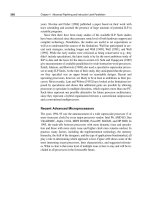
Figure 8.13 shows the data miss rates for our four applications, as we increase
the number of processors from one to 16, while keeping the problem size
8.3 Centralized Shared-Memory Architectures 667
constant. As we increase the number of processors, the total amount of cache in-
creases, usually causing the capacity misses to drop. In contrast, increasing the
processor count usually causes the amount of communication to increase, in turn
causing the coherence misses to rise. The magnitude of these two effects differs
by application.
In FFT, the capacity miss rate drops (from nearly 7% to just over 5%) but the
coherence miss rate increases (from about 1% to about 2.7%), leading to a con-
stant overall miss rate. Ocean shows a combination of effects, including some
that relate to the partitioning of the grid and how grid boundaries map to cache
blocks. For a typical 2D grid code the communication-generated misses are pro-
portional to the boundary of each partition of the grid, while the capacity misses
are proportional to the area of the grid. Therefore, increasing the total amount of
cache while keeping the total problem size fixed will have a more significant ef-
fect on the capacity miss rate, at least until each subgrid fits within an individual
processor’s cache. The significant jump in miss rate between one and two proces-
sors occurs because of conflicts that arise from the way in which the multiple
grids are mapped to the caches. This conflict is present for direct-mapped and
two-way set associative caches, but fades at higher associativities. Such conflicts
are not unusual in array-based applications, especially when there are multiple
grids in use at once. In Barnes and LU the increase in processor count has little
effect on the miss rate, sometimes causing a slight increase and sometimes caus-
ing a slight decrease.
Increasing the cache size has a beneficial effect on performance, since it re-
duces the frequency of costly cache misses. Figure 8.14 illustrates the change in
miss rate as cache size is increased, showing the portion of the miss rate due to
coherence misses and to uniprocessor capacity misses. Two effects can lead to a
miss rate that does not decrease—at least not as quickly as we might expect—as
cache size increases: inherent communication and plateaus in the miss rate. In-
herent communication leads to a certain frequency of coherence misses that are
not significantly affected by increasing cache size. Thus if the cache size is in-
creased while maintaining a fixed problem size, the coherence miss rate even-
tually limits the decrease in cache miss rate. This effect is most obvious in
Barnes, where the coherence miss rate essentially becomes the entire miss rate.
A less important effect is a temporary plateau in the capacity miss rate that
arises when the application has some fraction of its data present in cache but
some significant portion of the data set does not fit in the cache or in caches that
are slightly bigger. In LU, a very small cache (about 4 KB) can capture the pair of
16 × 16 blocks used in the inner loop; beyond that the next big improvement in
capacity miss rate occurs when both matrices fit in the caches, which occurs
when the total cache size is between 4 MB and 8 MB, a data point we will see lat-
er. This working set effect is partly at work between 32 KB and 128 KB for FFT,
where the capacity miss rate drops only 0.3%. Beyond that cache size, a faster
decrease in the capacity miss rate is seen, as some other major data structure be-
668 Chapter 8 Multiprocessors
FIGURE 8.13 Data miss rates can vary in nonobvious ways as the processor count is
increased from one to 16. The miss rates include both coherence and capacity miss rates.
The compulsory misses in these benchmarks are all very small and are included in the ca-
pacity misses. Most of the misses in these applications are generated by accesses to data
that is potentially shared, although in the applications with larger miss rates (FFT and Ocean),
it is the capacity misses rather than the coherence misses that comprise the majority of the
miss rate. Data is potentially shared if it is allocated in a portion of the address space used
for shared data. In all except Ocean, the potentially shared data is heavily shared, while in
Ocean only the boundaries of the subgrids are actually shared, although the entire grid is
treated as a potentially shared data object. Of course, since the boundaries change as we
increase the processor count (for a fixed-size problem), different amounts of the grid become
shared. The anomalous increase in capacity miss rate for Ocean in moving from one to two
processors arises because of conflict misses in accessing the subgrids. In all cases except
Ocean, the fraction of the cache misses caused by coherence transactions rises when a
fixed-size problem is run on an increasing number of processors. In Ocean, the coherence
misses initially fall as we add processors due to a large number of misses that are write own-
ership misses to data that is potentially, but not actually, shared. As the subgrids begin to fit
in the aggregate cache (around 16 processors), this effect lessens. The single processor
numbers include write upgrade misses, which occur in this protocol even if the data is not ac-
tually shared, since it is in the shared state. For all these runs, the cache size is 64 KB, two-
way set associative, with 32 blocks. Notice that the scale for each benchmark is different, so
that the behavior of the individual benchmarks can be seen clearly.
Miss rate
0%
3%
2%
1%
124
Processor count
FFT
816
8%
4%
7%
6%
5%
Miss rate
0%
6%
4%
2%
124
Processor count
Ocean
816
16%
18%
20%
8%
14%
12%
10%
Miss rate
0%
1%
124
Processor count
LU
816
2%
Miss rate
0%
124
Processor count
Barnes
816
1%
Coherence miss rate Capacity miss rate
8.3 Centralized Shared-Memory Architectures 669
gins to reside in the cache. These plateaus are common in programs that deal with
large arrays in a structured fashion.
Increasing the block size is another way to change the miss rate in a cache. In
uniprocessors, larger block sizes are often optimal with larger caches. In multi-
processors, two new effects come into play: a reduction in spatial locality for
shared data and an effect called false sharing. Several studies have shown that
shared data have lower spatial locality than unshared data. This means that for
shared data, fetching larger blocks is less effective than in a uniprocessor, be-
cause the probability is higher that the block will be replaced before all its con-
tents are referenced.
FIGURE 8.14 The miss rate usually drops as the cache size is increased, although co-
herence misses dampen the effect. The block size is 32 bytes and the cache is two-way
set-associative. The processor count is fixed at 16 processors. Observe that the scale for
each graph is different.
Miss rate
0%
4%
2%
32 64 128
Cache size (KB)
FFT
256
10%
6%
8%
Miss rate
0%
1%
1%
32 64 128
Cache size (KB)
LU
256
2%
2%
Miss rate
0%
6%
2%
4%
32 64 128
Cache size (KB)
Ocean
256
14%
10%
8%
12%
Miss rate
0%
1%
32 64 128
Cache size (KB)
Barnes
256
2%
1%
Coherence miss rate Capacity miss rate
670 Chapter 8 Multiprocessors
The second effect, false sharing, arises from the use of an invalidation-based
coherence algorithm with a single valid bit per block. False sharing occurs when
a block is invalidated (and a subsequent reference causes a miss) because some
word in the block, other than the one being read, is written into. If the word writ-
ten into is actually used by the processor that received the invalidate, then the ref-
erence was a true sharing reference and would have caused a miss independent of
the block size or position of words. If, however, the word being written and the
word read are different and the invalidation does not cause a new value to be
communicated, but only causes an extra cache miss, then it is a false sharing
miss. In a false sharing miss, the block is shared, but no word in the cache is actu-
ally shared, and the miss would not occur if the block size were a single word.
The following Example makes the sharing patterns clear.
EXAMPLE Assume that words x1 and x2 are in the same cache block in a clean state
in the caches of P1 and P2, which have previously read both x1 and x2.
Assuming the following sequence of events, identify each miss as a true
sharing miss, a false sharing miss, or a hit. Any miss that would occur if
the block size were one word is designated a true sharing miss.
ANSWER Here are classifications by time step:
1. This event is a true sharing miss, since x1 was read by P2 and needs
to be invalidated from P2.
2. This event is a false sharing miss, since x2 was invalidated by the
write of x1 in P1, but that value of x1 is not used in P2.
3. This event is a false sharing miss, since the block containing x1 is
marked shared due to the read in P2, but P2 did not read x1.
4. This event is a false sharing miss for the same reason as step 3.
5. This event is a true sharing miss, since the value being read was
written by P2.
■
Time P1 P2
1 Write x1
2 Read x2
3 Write x1
4 Write x2
5 Read x2
8.3 Centralized Shared-Memory Architectures 671
Figure 8.15 shows the miss rates as the cache block size is increased for a 16-
processor run with a 64-KB cache. The most interesting behavior is in Barnes,
where the miss rate initially declines and then rises due to an increase in the num-
ber of coherence misses, which probably occurs because of false sharing. In the
other benchmarks, increasing the block size decreases the overall miss rate. In
Ocean and LU, the block size increase affects both the coherence and capacity
miss rates about equally. In FFT, the coherence miss rate is actually decreased at
a faster rate than the capacity miss rate. This is because the communication in
FFT is structured to be very efficient. In less optimized programs, we would ex-
pect more false sharing and less spatial locality for shared data, resulting in more
behavior like that of Barnes.
FIGURE 8.15 The data miss rate drops as the cache block size is increased. All these
results are for a 16-processor run with a 64-KB cache and two-way set associativity. Once
again we use different scales for each benchmark.
Miss rate
0%
6%
4%
2%
16 32 64
Block size (bytes)
FFT
128
14%
10%
8%
12%
Miss rate
0%
2%
1%
16 32 64
Block size (bytes)
LU
128
4%
3%
Miss rate
0%
6%
2%
4%
16 32 64
Block size (bytes)
Ocean
128
14%
10%
8%
12%
Miss rate
0%
16 32 64
Block size (bytes)
Barnes
128
1%
Coherence miss rate Capacity miss rate
672 Chapter 8 Multiprocessors
Although the drop in miss rates with longer blocks may lead you to believe
that choosing a longer block size is the best decision, the bottleneck in bus-based
multiprocessors is often the limited memory and bus bandwidth. Larger blocks
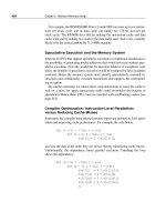
mean more bytes on the bus per miss. Figure 8.16 shows the growth in bus traffic
as the block size is increased. This growth is most serious in the programs that
have a high miss rate, especially Ocean. The growth in traffic can actually lead to
performance slowdowns due both to longer miss penalties and to increased bus
contention.
Performance of the Multiprogramming and OS Workload
In this subsection we examine the cache performance of the multiprogrammed
workload as the cache size and block size are changed. The workload remains the
same as described in the previous section: two independent parallel makes, each
using up to eight processors. Because of differences between the behavior of the
kernel and that of the user processes, we keep these two components separate.
FIGURE 8.16 Bus traffic for data misses climbs steadily as the block size in the data
cache is increased. The factor of 3 increase in traffic for Ocean is the best argument against
larger block sizes. Remember that our protocol treats ownership misses the same as other
misses, slightly increasing the penalty for large cache blocks; in both Ocean and FFT this ef-
fect accounts for less than 10% of the traffic.
7.0
4.0
5.0
6.0
3.0
2.0
1.0
Bytes per data reference
0.0
Block size (bytes)
16 32 64
128
FFT LU Barnes Ocean