Architectural design and practice Phần 1 pdf
Bạn đang xem bản rút gọn của tài liệu. Xem và tải ngay bản đầy đủ của tài liệu tại đây (414.74 KB, 24 trang )
DESIGN OF
MASONRY STRUCTURES
Third edition of Load Bearing Brickwork Design
A.W.Hendry, B.Sc., Ph.D., D.Sc, F.I.C.E., F.I. Struct.E., F.R.S.E.
B.P.Sinha, B.Sc., Ph.D., F.I. Struct.E., F.I.C.E., C. Eng.
and
S.R.Davies, B.Sc., Ph.D., M.I.C.E., C.Eng.
Department of Civil Engineering
University of Edinburgh, UK
E & FN SPON
An Imprint of Chapman & Hall
London · Weinheim · New York · Tokyo · Melbourne · Madras
©2004 Taylor & Francis
Published by E & FN Spon, an imprint of Chapman & Hall, 2–6
Boundary Row, London SE1 8HN, UK
Chapman & Hall, 2–6 Boundary Row, London SE1 8HN, UK
Chapman & Hall GmbH, Pappelallee 3, 69469 Weinheim, Germany
Chapman & Hall USA, 115 Fifth Avenue, New York, NY 10003, USA
Chapman & Hall Japan, ITP-Japan, Kyowa Building, 3F, 2–2–1
Hirakawacho, Chiyoda-ku, Tokyo 102, Japan
Chapman & Hall Australia, 102 Dodds Street, South Melbourne,
Victoria 3205, Australia
Chapman & Hall India, R.Seshadri, 32 Second Main Road, CIT
East, Madras 600 035, India
This edition published in the Taylor & Francis e-Library, 2004.
First edition 1997
© 1997 A.W.Hendry, B.P.Sinha and S.R.Davies
First published as Load Bearing Brickwork Design
(First edition 1981. Second edition 1986)
ISBN 0-203-36240-3 Master e-book ISBN
ISBN 0-203-37498-3 (Adobe eReader Format)
ISBN 0 419 21560 3 (Print Edition)
Apart from any fair dealing for the purposes of research or private study,
or criticism or review, as permitted under the UK Copyright Designs and
Patents Act, 1988, this publication may not be reproduced, stored, or
transmitted, in any form or by any means, without the prior permission in
writing of the publishers, or in the case of reprographic reproduction only in
accordance with the terms of the licences issued by the Copyright Licensing
Agency in the UK, or in accordance with the terms of licences issued by
the appropriate Reproduction Rights Organization outside the UK. Enquiries
concerning reproduction outside the terms stated here should be sent to
the publishers at the London address printed on this page.
The publisher makes no representation, express or implied, with regard to
the accuracy of the information contained in this book and cannot accept
any legal responsibility or liability for any errors or omissions that may be
made.
A catalogue record for this book is available from the British Library
©2004 Taylor & Francis
Contents
Preface to the third edition
Preface to the second edition
Preface to the first edition
Acknowledgements
1 Loadbearing masonry buildings
1.1 Advantages and development of loadbearing
masonry
1.2 Basic design considerations
1.3 Structural safety: limit state design
1.4 Foundations
1.5 Reinforced and prestressed masonry
2 Bricks, blocks and mortars
2.1 Introduction
2.2 Bricks and blocks
2.3 Mortar
2.4 Lime: non-hydraulic or semi-hydraulic lime
2.5 Sand
2.6 Water
2.7 Plasticized Portland cement mortar
2.8 Use of pigments
2.9 Frost inhibitors
2.10 Proportioning and strength
2.11 Choice of unit and mortar
©2004 Taylor & Francis
2.12 Wall ties
2.13 Concrete infill and grout
2.14 Reinforcing and prestressing steel
3 Masonry properties
3.1 General
3.2 Compressive strength
3.3 Strength of masonry in combined compression
and shear
3.4 The tensile strength of masonry
3.5 Stress-strain properties of masonry
3.6 Effects of workmanship on masonry strength
4 Codes of practice for structural masonry
4.1 Codes of practice: general
4.2 The basis and structure of BS 5628: Part 1
4.3 BS 5628: Part 2—reinforced
and prestressed masonry
4.4 Description of Eurocode 6 Part 1–1
(ENV 1996–1–1:1995)
5 Design for compressive loading
5.1 Introduction
5.2 Wall and column behaviour under axial load
5.3 Wall and column behaviour under eccentric load
5.4 Slenderness ratio
5.5 Calculation of eccentricity
5.6 Vertical load resistance
5.7 Vertical loading
5.8 Modification factors
5.9 Examples
6 Design for wind loading
6.1 Introduction
6.2 Overall stability
6.3 Theoretical methods for wind load analysis
6.4 Load distribution between unsymmetrically
arranged shear walls
7 Lateral load analysis of masonry panels
7.1 General
7.2 Analysis of panels with precompression
7.3 Approximate theory for lateral load analysis of walls
subjected to precompression with and without returns
©2004 Taylor & Francis
7.4 Effect of very high precompression
7.5 Lateral load design of panels without
precompression
8 Composite action between walls and other elements
8.1 Composite wall-beams
8.2 Interaction between wall panels and frames
9 Design for accidental damage
9.1 Introduction
9.2 Accidental loading
9.3 Likelihood of occurrence of progressive collapse
9.4 Possible methods of design
9.5 Use of ties
10 Reinforced masonry
10.1 Introduction
10.2 Flexural strength
10.3 Shear strength of reinforced masonry
10.4 Deflection of reinforced masonry beams
10.5 Reinforced masonry columns, using BS 5628: Part 2
10.6 Reinforced masonry columns, using ENV 1996–1–1
11 Prestressed masonry
11.1 Introduction
11.2 Methods of prestressing
11.3 Basic theory
11.4 A general flexural theory
11.5 Shear stress
11.6 Deflections
11.7 Loss of prestress
12 Design calculations for a seven-storey dormitory building
according to BS 5628
12.1 Introduction
12.2 Basis of design: loadings
12.3 Quality control: partial safety factors
12.4 Calculation of vertical loading on walls
12.5 Wind loading
12.6 Design load
12.7 Design calculation according to EC6 Part 1–1
(ENV 1996–1:1995)
12.8 Design of panel for lateral loading:
BS 5628 (limit state)
12.9 Design for accidental damage
©2004 Taylor & Francis
12.10 Appendix: a typical design calculation
for interior-span solid slab
13 Movements in masonry buildings
13.1 General
13.2 Causes of movement in buildings
13.3 Horizontal movements in masonry walls
13.4 Vertical movements in masonry walls
Notation
BS 5628
EC6 (where different from BS 5628)
Definition of terms used in masonry
References and further reading
©2004 Taylor & Francis
Preface to the third edition
The first edition of this book was published in 1981 as Load Bearing
Brickwork Design, and dealt with the design of unreinforced structural
brickwork in accordance with BS 5628: Part 1. Following publication of
Part 2 of this Code in 1985, the text was revised and extended to cover
reinforced and prestressed brickwork, and the second edition published
in 1987.
The coverage of the book has been further extended to include
blockwork as well as brickwork, and a chapter dealing with movements
in masonry structures has been added. Thus the title of this third edition
has been changed to reflect this expanded coverage. The text has been
updated to take account of amendments to Part 1 of the British Code,
reissued in 1992, and to provide an introduction to the forthcoming
Eurocode 6 Part 1–1, published in 1996 as ENV 1996–1–1. This document
has been issued for voluntary use prior to the publication of EC6 as a
European Standard. It includes a number of ‘boxed’ values, which are
indicative: actual values to be used in the various countries are to be
prescribed in a National Application Document accompanying the ENV.
Edinburgh, June 1996
©2004 Taylor & Francis
Preface to the second edition
Part 2 of BS 5628 was published in 1985 and relates to reinforced and
prestressed masonry which is now finding wider application in practice.
Coverage of the second edition of this book has therefore been extended
to include consideration of the principles and application of this form of
construction.
Edinburgh, April 1987
©2004 Taylor & Francis
Preface to the first edition
The structural use of brick masonry has to some extent been hampered
by its long history as a craft based material and some years ago its
disappearance as a structural material was being predicted. The fact that
this has not happened is a result of the inherent advantages of brickwork
and the design of brick masonry structures has shown steady
development, based on the results of continuing research in many
countries. Nevertheless, structural brickwork is not used as widely as it
could be and one reason for this lies in the fact that design in this
medium is not taught in many engineering schools alongside steel and
concrete. To help to improve this situation, the authors have written this
book especially for students in university and polytechnic courses in
structural engineering and for young graduates preparing for
professional examination in structural design.
The text attempts to explain the basic principles of brickwork design,
the essential properties of the materials used, the design of various structural
elements and the procedure in carrying out the design of a complete
building. In practice, the basic data and methodology for structural design
in a given material is contained in a code of practice and in illustrating
design procedures it is necessary to relate these to a particular document
of this kind. In the present case the standard referred to, and discussed in
some detail, is the British BS 5628 Part 1, which was first published in 1978.
This code is based on limit state principles which have been familiar to
many designers through their application to reinforced concrete design
but which are summarised in the text.
No attempt has been made in this introductory book to give extensive
lists of references but a short list of material for further study is included
which will permit the reader to follow up any particular topic in greater
depth.
Preparation of this book has been based on a study of the work of a
large number of research workers and practising engineers to whom the
©2004 Taylor & Francis
authors acknowledge their indebtedness. In particular, they wish to
express their thanks to the following for permission to reproduce
material from their publications, as identified in the text: British
Standards Institution; Institution of Civil Engineers; the Building
Research Establishment; Structural Clay Products Ltd.
Edinburgh, June 1981 A.W.Hendry
B.P.Sinha
S.R.Davies
©2004 Taylor & Francis
Acknowledgements
Preparation of this book has been based on a study of the work of a large
number of research workers and practising engineers, to whom the
authors acknowledge their indebtedness. In particular, they wish to
express thanks to the British Standards Institution, the Institution of Civil
Engineers, the Building Research Establishment and Structural Clay
Products Ltd for their permission to reproduce material from their
publications, as identified in the text. They are also indebted to the Brick
Development Association for permission to use the illustration of Cavern
Walks, Liverpool, for the front cover.
Extracts from DD ENV 1996–1–1:1995 are reproduced with the
permission of BSI. Complete copies can be obtained by post from BSI
Customer Services, 389 Chiswick High Road, London W4 4AL. Users
should be aware that DD ENV 1996–1–1:1995 is a prestandard; additional
information may be available in the national foreword in due course.
©2004 Taylor & Francis
1
Loadbearing masonry buildings
1.1 ADVANTAGES AND DEVELOPMENT OF LOADBEARING
MASONRY
The basic advantage of masonry construction is that it is possible to use
the same element to perform a variety of functions, which in a
steelframed building, for example, have to be provided for separately,
with consequent complication in detailed construction. Thus masonry
may, simultaneously, provide structure, subdivision of space, thermal
and acoustic insulation as well as fire and weather protection. As a
material, it is relatively cheap but durable and produces external wall
finishes of very acceptable appearance. Masonry construction is flexible
in terms of building layout and can be constructed without very large
capital expenditure on the part of the builder.
In the first half of the present century brick construction for multi-
storey buildings was very largely displaced by steel- and
reinforcedconcrete-framed structures, although these were very often
clad in brick. One of the main reasons for this was that until around 1950
loadbearing walls were proportioned by purely empirical rules, which
led to excessively thick walls that were wasteful of space and material
and took a great deal of time to build. The situation changed in a number
of countries after 1950 with the introduction of structural codes of
practice which made it possible to calculate the necessary wall thickness
and masonry strengths on a more rational basis. These codes of practice
were based on research programmes and building experience, and,
although initially limited in scope, provided a sufficient basis for the
design of buildings of up to thirty storeys. A considerable amount of
research and practical experience over the past 20 years has led to the
improvement and refinement of the various structural codes. As a result,
the structural design of masonry buildings is approaching a level similar
to that applying to steel and concrete.
©2004 Taylor & Francis
1.2 BASIC DESIGN CONSIDERATIONS
Loadbearing construction is most appropriately used for buildings in
which the floor area is subdivided into a relatively large number of
rooms of small to medium size and in which the floor plan is repeated on
each storey throughout the height of the building. These considerations
give ample opportunity for disposing loadbearing walls, which are
continuous from foundation to roof level and, because of the moderate
floor spans, are not called upon to carry unduly heavy concentrations of
vertical load. The types of buildings which are compatible with these
requirements include flats, hostels, hotels and other residential
buildings.
The form and wall layout for a particular building will evolve from
functional requirements and site conditions and will call for
collaboration between engineer and architect. The arrangement chosen
will not usually be critical from the structural point of view provided
that a reasonable balance is allowed between walls oriented in the
principal directions of the building so as to permit the development of
adequate resistance to lateral forces in both of these directions. Very
unsymmetrical arrangements should be avoided as these will give rise to
torsional effects under lateral loading which will be difficult to calculate
and which may produce undesirable stress distributions.
Stair wells, lift shafts and service ducts play an important part in
deciding layout and are often of primary importance in providing lateral
rigidity.
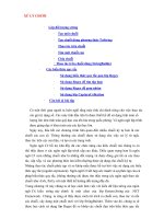
The great variety of possible wall arrangements in a masonry building
makes it rather difficult to define distinct types of structure, but a rough
classification might be made as follows:
• Cellular wall systems
• Simple or double cross-wall systems
• Complex arrangements.
A cellular arrangement is one in which both internal and external walls
are loadbearing and in which these walls form a cellular pattern in plan.
Figure 1.1 (a) shows an example of such a wall layout.
The second category includes simple cross-wall structures in which
the main bearing walls are at right angles to the longitudinal axis of the
building. The floor slabs span between the main cross-walls, and
longitudinal stability is achieved by means of corridor walls, as shown in
Fig. 1.1(b). This type of structure is suitable for a hostel or hotel building
having a large number of identical rooms. The outer walls may be clad in
non-loadbearing masonry or with other materials.
It will be observed that there is a limit to the depth of building which
can be constructed on the cross-wall principle if the rooms are to have
©2004 Taylor & Francis
effective day-lighting. If a deeper block with a service core is required, a
somewhat more complex system of cross-walls set parallel to both major
axes of the building may be used, as in Fig. 1.1(c).
All kinds of hybrids between cellular and cross-wall arrangements are
possible, and these are included under the heading ‘complex’, a typical
example being shown in Fig. 1.1(d).
Considerable attention has been devoted in recent years to the
necessity for ensuring the ‘robustness’ of buildings. This has arisen from
a number of building failures in which, although the individual
members have been adequate in terms of resisting their normal service
loads, the building as a whole has still suffered severe damage from
abnormal loading, resulting for example from a gas explosion or from
vehicle impact. It is impossible to quantify loads of this kind, and what is
required is to construct buildings in such a way that an incident of this
category does not result in catastrophic collapse, out of proportion to the
initial forces. Meeting this requirement begins with the selection of wall
layout since some arrangements are inherently more resistant to
abnormal forces than others. This point is illustrated in Fig. 1.2: a
building consisting only of floor slabs and cross-walls (Fig. 1.2(a)) is
obviously unstable and liable to collapse under the influence of small
lateral forces acting parallel to its longer axis. This particular weakness
could be removed by incorporating a lift shaft or stair well to provide
resistance in the weak direction, as in Fig. 1.2(b). However, the flank or
gable walls are still vulnerable, for example to vehicle impact, and
limited damage to this wall on the lowermost storey would result in the
collapse of a large section of the building.
A building having a wall layout as in Fig. 1.2(c) on the other hand is
clearly much more resistant to all kinds of disturbing forces, having a
high degree of lateral stability, and is unlikely to suffer extensive damage
from failure of any particular wall.
Robustness is not, however, purely a matter of wall layout. Thus a
floor system consisting of unconnected precast planks will be much less
resistant to damage than one which has cast-in-situ concrete floors with
two-way reinforcement. Similarly, the detailing of elements and their
connections is of great importance. For example, adequate bearing of
beams and slabs on walls is essential in a gravity structure to prevent
possible failure not only from local over-stressing but also from relative
movement between walls and other elements. Such movement could
result from foundation settlement, thermal or moisture movements. An
extreme case occurs in seismic areas where positive tying together of
walls and floors is essential.
The above discussion relates to multi-storey, loadbearing masonry
buildings, but similar considerations apply to low-rise buildings where
there is the same requirement for essentially robust construction.
©2004 Taylor & Francis
1.3 STRUCTURAL SAFETY: LIMIT STATE DESIGN
The objective of ensuring a fundamentally stable or robust building, as
discussed in section 1.2, is an aspect of structural safety. The measures
adopted in pursuit of this objective are to a large extent qualitative and
conceptual whereas the method of ensuring satisfactory structural
performance in resisting service loads is dealt with in a more
quantitative manner, essentially by trying to relate estimates of these
loads with estimates of material strength and rigidity.
The basic aim of structural design is to ensure that a structure should
fulfil its intended function throughout its lifetime without excessive
deflection, cracking or collapse. The engineer is expected to meet this
aim with due regard to economy and durability. It is recognized,
however, that it is not possible to design structures which will meet these
requirements in all conceivable circumstances, at least within the limits
of financial feasibility. For example, it is not expected that normally
designed structures will be capable of resisting conceivable but
improbable accidents which would result in catastrophic damage, such
as impact of a large aircraft. It is, on the other hand, accepted that there is
uncertainty in the estimation of service loads on structures, that the
strength of construction materials is variable, and that the means of
relating loads to strength are at best approximations. It is possible that an
unfavourable combination of these circumstances could result in
structural failure; design procedures should, therefore, ensure that the
probability of such a failure is acceptably small.
The question then arises as to what probability of failure is ‘acceptably
small’. Investigation of accident statistics suggests that, in the context of
buildings, a one-in-a-million chance of failure leading to a fatality will
be, if not explicitly acceptable to the public, at least such as to give rise to
little concern. In recent years, therefore, structural design has aimed,
indirectly, to provide levels of safety consistent with a probability of
failure of this order.
Consideration of levels of safety in structural design is a recent
development and has been applied through the concept of ‘limit state’
design. The definition of a limit state is that a structure becomes unfit for
its intended purpose when it reaches that particular condition. A limit
state may be one of complete failure (ultimate limit state) or it may define
a condition of excessive deflection or cracking (serviceability limit state).
The advantage of this approach is that it permits the definition of direct
criteria for strength and serviceability taking into account the
uncertainties of loading, strength and structural analysis as well as
questions such as the consequences of failure.
The essential principles of limit state design may be summarized as
follows. Considering the ultimate limit state of a particular structure, for
©2004 Taylor & Francis
failure to occur:
(1.1)
where is the design strength of the structure, and
the design loading effects. Here
␥
m
and
␥
f
are partial safety factors; R
k
and
Q
k
are characteristic values of resistance and load actions, generally chosen
such that 95% of samples representing R
k
will exceed this value and 95%
of the applied forces will be less than Q
k
.
The probability of failure is then:
(1.2)
If a value of p, say 10
-6
, is prescribed it is possible to calculate values of
the partial safety factors,
␥
m
and
␥
f
, in the limit state equation which
would be consistent with this probability of failure. In order to do this,
however, it is necessary to define the load effects and structural
resistance in statistical terms, which in practice is rarely possible. The
partial safety factors, therefore, cannot be calculated in a precise way and
have to be determined on the basis of construction experience and
laboratory testing against a background of statistical theory. The
application of the limit state approach as exemplified by the British Code
of Practice BS 5628 and Eurocode 6 (EC 6) is discussed in Chapter 4.
1.4 FOUNDATIONS
Building structures in loadbearing masonry are characteristically stiff in
the vertical direction and have a limited tolerance for differential
movement of foundations. Studies of existing buildings have suggested
that the maximum relative deflection (i.e. the ratio of deflection to the
length of the deflected part) in the walls of multi-storeyed loadbearing
brickwork buildings should not exceed 0.0003 in sand or hard clay and
0.0004 in soft clay. These figures apply to walls whose length exceeds
three times their height. It has also been suggested that the maximum
average settlement of a brickwork building should not exceed 150 mm.
These figures are, however, purely indicative, and a great deal depends
on the rate of settlement as well as on the characteristics of the masonry.
Settlement calculations by normal soil mechanics techniques will
indicate whether these limits are likely to be exceeded. Where problems
have arisen, the cause has usually been associated with particular types
of clay soils which are subject to excessive shrinkage in periods of dry
weather. In these soils the foundations should be at a depth of not less
than 1 m in order to avoid moisture fluctuations.
High-rise masonry buildings are usually built on a reinforced concrete
raft of about 600mm thickness. The wall system stiffens the raft and
©2004 Taylor & Francis
helps to ensure uniform ground pressures, whilst the limitation on floor
spans which applies to such structures has the effect of minimizing the
amount of reinforcement required in the foundation slab. Under
exceptionally good soil conditions it may be possible to use spread
footings, whilst very unfavourable conditions may necessitate piling
with ground beams.
1.5 REINFORCED AND PRESTRESSED MASONRY
The preceding paragraphs in this chapter have been concerned with the
use of unreinforced masonry. As masonry has relatively low strength in
tension, this imposes certain restrictions on its field of application.
Concrete is, of course, also a brittle material but this limitation is
overcome by the introduction of reinforcing steel or by prestressing. The
corresponding use of these techniques in masonry construction is not
new but, until recently, has not been widely adopted. This was partly due
to the absence of a satisfactory code of practice, but such codes are now
available so that more extensive use of reinforced and prestressed
masonry may be expected in future.
By the adoption of reinforced or prestressed construction the scope of
masonry can be considerably extended. An example is the use of
prestressed masonry walls of cellular or fin construction for sports halls
and similar buildings where the requirement is for walls some 10 m in
height supporting a long span roof. Other examples include the use of
easily constructed, reinforced masonry retaining walls and the
reinforcement of laterally loaded walls to resist wind or seismic forces.
In appropriate cases, reinforced masonry will have the advantage over
concrete construction of eliminating expensive shuttering and of
producing exposed walls of attractive appearance without additional
expense.
Reinforcement can be introduced in masonry elements in several
ways. The most obvious is by placing bars in the bed joints or collar
joints, but the diameter of bars which can be used in this way is limited.
A second possibility is to form pockets in the masonry by suitable
bonding patterns or by using specially shaped units. The steel is
embedded in these pockets either in mortar or in small aggregate
concrete (referred to in the USA as ‘grout’). The third method, suitable for
walls or beams, is to place the steel in the cavity formed by two leaves (or
wythes) of brickwork which is subsequently filled with small aggregate
concrete. This is known as grouted cavity construction. Elements built in
this way can be used either to resist in-plane loading, as beams or shear
walls, or as walls under lateral loading. In seismic situations it is possible
to bond grouted cavity walls to floor slabs to give continuity to the
structure. Finally, reinforcement can be accommodated in hollow block
©2004 Taylor & Francis
walls or piers, provided that the design of the blocks permits the
formation of continuous ducts for the reinforcing bars.
Prestressed masonry elements are usually post-tensioned, the steel, in
strand or bar form, being accommodated in ducts formed in the
masonry. In some examples of cellular or diaphragm wall construction
the prestressing steel has been placed in the cavity between the two
masonry skins, suitably protected against corrosion. It is also possible to
prestress circular tanks with circumferential wires protected by an outer
skin of brickwork built after prestressing has been carried out.
©2004 Taylor & Francis
2
Bricks, blocks and mortars
2.1 INTRODUCTION
Masonry is a well proven building material possessing excellent
properties in terms of appearance, durability and cost in comparison
with alternatives. However, the quality of the masonry in a building
depends on the materials used, and hence all masonry materials must
conform to certain minimum standards. The basic components of
masonry are block, brick and mortar, the latter being in itself a composite
of cement, lime and sand and sometimes of other constituents. The object
of this chapter is to describe the properties of the various materials
making up the masonry.
2.2 BRICKS AND BLOCKS
2.2.1 Classification
Brick is defined as a masonry unit with dimensions (mm) not exceeding
337.5×225×112.5 (L×w×t). Any unit with a dimension that exceeds any
one of those specified above is termed a block. Blocks and bricks are
made of fired clay, calcium silicate or concrete. These must conform to
relevant national standards, for example in the United Kingdom to BS
3921 (clay units), BS 187 (calcium silicate) and BS 6073: Part 1 (concrete
units). In these standards two classes of bricks are identified, namely
common and facing; BS 3921 identifies a third category, engineering:
• Common bricks are suitable for general building work.
• Facing bricks are used for exterior and interior walls and available in a
variety of textures and colours.
• Engineering bricks are dense and strong with defined limits of
absorption and compressive strength as given in Table 2.2.
©2004 Taylor & Francis
Bricks must be free from deep and extensive cracks, from damage to
edges and corners and also from expansive particles of lime.
Bricks are also classified according to their resistance to frost and the
maximum soluble salt content.
(a) Designation according to frost resistance
• Frost resistant (F): These bricks are durable in extreme conditions of
exposure to water and freezing and thawing. These bricks can be used
in all building situations.
• Moderately frost resistant (M): These bricks are durable in the normal
condition of exposure except in a saturated condition and subjected to
repeated freezing and thawing.
• Not frost resistant (O): These bricks are suitable for internal use. They
are liable to be damaged by freezing and thawing unless protected by
an impermeable cladding during construction and afterwards.
(b) Designation according to maximum soluble salt content
• Low (L): These clay bricks must conform to the limit prescribed by BS
3921 for maximum soluble salt content given in Table 2.1. All
engineering and some facing or common bricks may come under this
category.
• Normal (N): There is no special requirement or limit for soluble salt
content.
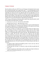
2.2.2 Varieties
Bricks may be wire cut, with or without perforations, or pressed with
single or double frogs or cellular. Perforated bricks contain holes; the
cross-sectional area of any one hole should not exceed 10% and the
volume of perforations 25% of the total volume of bricks. Cellular bricks
will have cavities or frogs exceeding 20% of the gross volume of the
brick. In bricks having frogs the total volume of depression should be
Table 2.1 Maximum salt content of low (L) brick (BS 3921)
©2004 Taylor & Francis
less than or equal to 20%. In the United Kingdom, calcium silicate or
concrete bricks are also used, covered by BS 187 and BS 6073.
Bricks of shapes other than rectangular prisms are referred to as
‘standard special’ and covered by BS 4729.
Concrete blocks may be solid, cellular or hollow.
Different varieties of bricks and blocks are shown in Figs. 2.1 and 2.2.
2.2.3 Compressive strength
From the structural point of view, the compressive strength of the unit is
the controlling factor. Bricks of various strengths are available to suit a
wide range of architectural and engineering requirements. Table 2.2
gives a classification of bricks according to the compressive strength. For
low-rise buildings, bricks of 5.2 N/mm
2
should be sufficient. For
dampproof courses, low-absorption engineering bricks are usually
required. For reinforced and prestressed brickwork, it is highly unlikely
that brick strength lower than 20 N/mm
2
will be used in the UK.
Calcium silicate bricks of various strengths are also available. Table 2.3
gives the class and strength of these bricks available.
Concrete bricks of minimum average strength of 21 to 50 N/mm
2
are
available. Solid, cellular and hollow concrete blocks of various
thicknesses and strengths are manufactured to suit the design
requirements. Both the thickness and the compressive strength of
concrete blocks are given in Table 2.4.
2.2.4 Absorption
Bricks contain pores; some may be ‘through’ pores, others are ‘cul-de-sac’
or even sealed and inaccessible. The ‘through’ pores allow air to escape
in the 24 h absorption test (BS 3921) and permit free passage of water.
However, others in a simple immersion test or vacuum test do not allow
the passage of water, hence the requirement for a 5 h boiling or vacuum
test. The absorption is the amount of water which is taken up to fill these
pores in a brick by displacing the air. The saturation coefficient is the
ratio of 24 h cold absorption to maximum absorption in vacuum or
boiling. The absorption of clay bricks varies from 4.5 to 21% by weight
and those of calcium silicate from 7 to 21% and concrete units 7 to 10% by
weight. The saturation coefficient of bricks may range approximately
from 0.2 to 0.88. Neither the absorption nor the saturation coefficient
necessarily indicates the liability of bricks to decay by frost or chemical
action. Likewise, absorption is not a mandatory requirement for concrete
bricks or blocks as there is no relationship between absorption and
durability.
©2004 Taylor & Francis
Fig. 2.1 Types of standard bricks.
©2004 Taylor & Francis
(b) Moisture movement
One of the common causes of cracking and decay of building materials is
moisture movement, which may be wholly or partly reversible or, in
some circumstances, irreversible. The designer should be aware of the
magnitude of this movement.
Clay bricks being taken from the kiln expand owing to absorption of
water from the atmosphere. The magnitude of this expansion depends
on the type of brick and its firing temperature and is wholly irreversible.
A large part of this irreversible movement takes place within a few days,
as shown in Fig. 2.3, and the rest takes place over a period of about six
months. Because of this moisture movement, bricks coming fresh from
the kiln should never be delivered straight to the site. Generally, the
accepted time lag is a fortnight. Subsequent moisture movement is
unlikely to exceed 0.02%.
In addition to this, bricks also undergo partly or wholly reversible
expansion or contraction due to wetting or drying. This is not very
significant except in the case of the calcium silicate bricks. Hence, the
designer should incorporate ‘expansion’ joints in all walls of any
considerable length as a precaution against cracking. Normally,
movement joints in calcium silicate brickwork may be provided at
intervals of 7.5 to 9.0 m depending upon the moisture content of bricks at
the time of laying. In clay brickwork expansion joints at intervals of 12.2
to 18.3 m may be provided to accommodate thermal or other
movements.
The drying shrinkage of concrete brick/blockwork should not exceed
0.06%. In concrete masonry, the movement joint should be provided at 6
Fig. 2.3 Expansion of kiln-fresh bricks due to absorption of moisture from
atmosphere.
©2004 Taylor & Francis