Industrial Control Student Guide Version 1.1 phần 8 ppsx
Bạn đang xem bản rút gọn của tài liệu. Xem và tải ngay bản đầy đủ của tài liệu tại đây (571.99 KB, 24 trang )
Experiment #7: Real-time Control and Data Logging
Note that the program will reset the time to 05:53 every time the BASIC Stamp is reset. This can occur from
program loading, manual Stamp reset, power supply cycling, and sometimes the COM port or computer
cycling. The start time is appropriate for what we are discussing in this section, but in later sections you may
want to set the values of the start-time to actual values.
'***** Initialize Settings *******
Time
=
$0553
Seconds
=
$00
CTimeLow
CON
$1800
CTimeHigh
CON
$0600
LowTempSP
CON
900
HighTempSP
CON
1000
'*********************************
GOSUB SetTime
' Define initial time
' Define time to go low temp.
' Define time to go high temp.
' Define low temp.
' Define high temp.
' Set RTC (Remark out if time ok)
Note: If power is removed from the DS1302 Real Time Clock it will power-up with unpredictable values in the
time registers with Gosub SetTime remarked out.
The times for changing temperature and their new values are also set here. GOSUB SetTime sets the real
time clock to the specified time. Once the proper time is set, this line may be remarked out and downloaded
again to prevent the time from being reset to 05:53 if the BASIC Stamp is reset.
The program uses two sets of variables for time, one to set/hold the current time, and another to hold the
time we wish to change the thermostat. Note that the word variable of Time and CTime are further broken
down into Hours and Minutes:
Time
Hours
Minutes
VAR
VAR
VAR
WORD
TIME.HIGHBYTE
TIME.LOWBYTE
' Word to hold full time
' High byte is hours
' Low byte is hours
The variable Hours is assigned to be the high byte of the word variable Time, or those two BCD positions
representing the hour. The same is true for minutes and the lower 2 positions. This is a very powerful tool
when parts of a single variable need to be addressed individually.
Program 7.1 starts time 7 minutes before switching to the working-hours temperature. This should provide
time for temperature to stabilize at the lower temperature. Figure 7.4 is a plot of the run.
Industrial Control Version 1.1 • Page 197
Experiment #7: Real-time Control and Data Logging
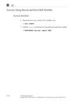
Figure 7.4: Time-Controlled 'Building Heating’
The StampPlot Lite user status box displays the current time and the time that the next change is set to occur.
The time in the status box may appear to be changing at irregular intervals, but that is a result of timing of the
BS2 in displaying the data and not the time kept by the RTC. The message area displays both the time a change
occurred and the new setpoint.
The plot illustrates On/Off control at the 90 F setpoint, and the switch to the 100 F setpoint at 06:00. Using
the RTC, adding more output devices, and expanding the control section of the code, we could add numerous
time-based events to occur over the course of a day.
Download and run program 7.1. Monitor with StampPlot Lite through at least the 06:00 change. You will need
to wait another 12 hours to see if it switches back to the low setpoint at 18:00... Have time to wait?
Page 198 • Industrial Control Version 1.1
Experiment #7: Real-time Control and Data Logging
Questions and Challenges:
1) The time data stored in the DS1302 uses the ______ number system.
2) Add a temperature setting of 95 F to be enabled between 4:00PM (16:00) and 6:00 PM (18:00). Modify the
starting time and initial temperature to test both times.
3) Use the LED on P8 to simulate a house lamp. Add code to energize it at 8:00 PM (20:00) and de-energize
it at 11:00 PM (23:00). Modify the starting time of RTC to test both times.
Exercise #2: Interval Timing
Instead of having events occur at defined times of the day, often a process may need to perform actions at
certain intervals of time. The annealing process is one such process. In this example a metal is heated at a
given temperature for a set amount of time, raised to another temperature for a set amount of time, and
then cooled to yet another temperature. This tempers the metal and gives it certain desirable characteristics,
such as hardness and tensile strength.
Since we are dealing with intervals of time instead of absolute times, we will need to perform calculations to
find the target time that marks the end of an interval. The time interval must be added to the start time of
the temperature phase. This sounds simple, but it isn’t.
If you remember, our time keeping is performed in BCD, a subset of hexadecimal. When adding values
together for time, the BASIC Stamp 2 is working in hexadecimal. Take the example of 38 seconds + 5 seconds.
We know this should yield a result of 43 seconds, but since we are really adding $38 + $05 (hexadecimal), our
result is $3D (counting 5: $39, $3A, $3B, $3C, $3D). If we compare that value to a time from the RTC, it will
never occur!
We need to decimal adjust the result. This is done by checking whether the digit exceeds the legal BCD range (
>9) and adding 6 if it does. Test this with the above result:
$3D + $06 = $43 (counting 6: $3E, $3F, $40, $41, $42, $43). Success! We now have the result we needed for
BCD values.
Some other issues we need to contend with is that either the one's or ten's place may need to be adjusted.
Depending on the result we may need to carry over into our minutes or hours. Seconds and minutes need to
roll over at 60, while hours needs to roll over at 24.
Industrial Control Version 1.1 • Page 199
Experiment #7: Real-time Control and Data Logging
This is the general sequence, or algorithm, our program will use:
• Check whether the one's place in seconds is legal BCD (<$A).
No: Add 6 to seconds.
• Check whether the seconds exceeded <60.
No: Subtract 60 from seconds. Add one to minutes.
• Check whether the one's place in minutes is legal BCD (<$A).
No: Add 6 to minutes
Here’s the code:
AdjustTime:
'BCD Time adjust routine
IF Cseconds.lownib < $A THEN HighSec
Cseconds = Cseconds + 6
HighSec:
If Cseconds < $60 Then LowMin
Cseconds = Cseconds - $60
Cminutes = Cminutes + 1
LowMin:
IF Cminutes.lownib < $A THEN HighMin
Cminutes = Cminutes + 6
HighMin:
IF Cminutes < $60 THEN LowHours
CMinutes = Cminutes - $60
Chours = Chours + 1
LowHours:
IF CHours.lownib < $A THEN HighHours
Chours = Chours + 6
HighHours:
IF Chours < $24 THEN AdjustDone
Chours = Chours - $24
AdjustDone:
RETURN
There is one case where this algorithm won't provide the correct results: When we add a value greater than 6
in any position when the place exceeds 7. Take the example of $58 + $08. Adding in hex we get $60. This
returns a valid BCD number, just not one that is computationally correct for BCD. An easy fix for adding 8, is
to add 4, adjust, then add 4 more and adjust again. Easier yet would be to not choose timing intervals
containing the digits 7, 8, or 9!
In this section we will simulate this process with our incubator, but keep in mind annealing typically heats in
thousands of degrees. This is the sequence our annealing process will follow:
•
•
Phase 1: Heat at 95.0 F for 5 minutes.
Phase 2: Heat to 100 F for 15 minutes.
Page 200 • Industrial Control Version 1.1
Experiment #7: Real-time Control and Data Logging
•
•
Phase 3: Cool to 85.0 F for 10 minutes.
Process complete, start over for next material sample.
Make the following changes/additions to program 7.1 for Program 7.2.
' Program 7.2: Interval Timing
' Controls temperature at 3 levels for set amount of time
'****** Initialize Settings *****
Time
=
$1200
Seconds =
$00
' Time to set clock
PTemp1 CON
PTemp2 CON
PTemp3 CON
' 1st phase temperature
' 2nd phase temperature
' 3rd phase temperature
950
1000
850
PTime1 CON
$05
PTime2 CON
$15
PTime3 CON
$10
'*******************************
Gosub SetTime
Setpoint = PTemp1
Gosub ReadRTCBurst
CTime = Time
CMinutes = Minutes + PTime1
Gosub AdjustTime
'
'
'
'
Do not
Length
Length
Length
use digits 7 or above
of phase 1
of phase 2
of phase 3
'
'
'
'
'
'
Set clock (Remark out once set)
Initial setpoint to 1st phase temp
Get clock reading
Set Change time to current
Add Phase 1 time
BCD adjust time
' Define A/D constants & variables
(Middle section of code remains unchanged)
TimeControl:
' Check if ready for change
IF (Time = CTime) AND (Setpoint = PTemp3) THEN Phase1
IF (Time = CTime) AND (Setpoint = PTemp1) THEN Phase2
IF (Time = CTime) AND (Setpoint = PTemp2) THEN Phase3
Return
Phase1:
' Phase 1 - Set for phase 1
Debug "Phase 3 Complete - Next Sample",CR
Debug "!BELL",CR
Setpoint = PTemp1
Cminutes = Cminutes + PTime1
GOTO SetNext
Phase2:
' Phase 2 - Set for phase 2
DEBUG "Phase 1 Complete",CR
Setpoint = PTemp2
Industrial Control Version 1.1 • Page 201
Experiment #7: Real-time Control and Data Logging
Cminutes = Cminutes + PTime2
GOTO SetNext
Phase3:
' Phase 3 - Set for phase 3
DEBUG "Phase 2 Complete",CR
Setpoint = PTemp3
Cminutes = Cminutes + PTime3
SetNext:
GOSUB AdjustTIme
' BCD adjust time
DEBUG "Time: ", hex2 hours,":",hex2 minutes,":",hex2 seconds
DEBUG "-- Setpoint: ", dec setpoint,cr
RETURN
AdjustTime:
IF Cseconds.lownib < $A THEN HighSec
Cseconds = Cseconds + 6
HighSec:
If Cseconds < $60 Then LowMin
Cseconds = Cseconds - $60
Cminutes = Cminutes + 1
LowMin:
IF Cminutes.lownib < $A THEN HighMin
Cminutes = Cminutes + 6
HighMin:
IF Cminutes < $60 THEN LowHours
CMinutes = Cminutes - $60
Chours = Chours + 1
LowHours:
IF CHours.lownib < $A THEN HighHours
Chours = Chours + 6
HighHours:
IF Chours < $24 THEN AdjustDone
Chours = Chours - $24
AdjustDone:
RETURN
Page 202 • Industrial Control Version 1.1
'BCD Time adjust routine
Experiment #7: Real-time Control and Data Logging
Figure 7.5: Interval Timer Plot
Figure 7.5 is a screen shot of a sample run. Notice there is 3 distinct temperature phases, and then it repeats.
Download and run program 7.2. Use StampPlot Lite to monitor your system.
Questions and Challenges:
1) Why is using the RTC preferable for long-interval timing instead of PBASIC Pause commands?
2) Add the following
$15 + $15
hexadecimal
values
and
decimal
adjust
the
results
(show
work):
3) Modify the program to add a 5-minute phase 4 at 80.0 F.
Industrial Control Version 1.1 • Page 203
Experiment #7: Real-time Control and Data Logging
Exercise #3: Data Logging
Data logging does not fall into the area of process-control, but it is an important subject, and since the RTC is
connected, this is an appropriate time to discuss it. The majority of our experiments have used StampPlot
Lite to graphically display current conditions in our system. Of course, one of the biggest benefits of
microcontrollers are that they are self-contained and do not require a PC. All the experiments in this text
would operate properly whether the data was being plotted on a PC or not. We simply wouldn't have any
direct feedback of the status.
Data logging is used to collect data and store it locally by the microcontroller. This data may then be
downloaded later for analysis. Some examples of this include remote weather stations and Space-Shuttle
experiments. Due to location or other factors, it may not be practical to be collecting data on a PC in real
time.
When data is logged to memory, it is important to make sure the hardware, programming, and time keeping is
as stable as possible. The data-logger may not be accessed for very long periods of time. Unintentionally
resetting the Stamp will usually lose your data and start the programming over. The Stamp is easily reset by
pressing the reset button, by connecting it to a computer sometimes, or possibly even a temporary loss
power.
Just as BASIC Stamp programs are stored in non-volatile memory (remains with loss of power) in EEPROM, we
may also write data directly into the EEPROM. The BASIC Stamp 2 has 2048 bytes of available EEPROM
memory for program and data storage. Figure 7.6 shows the BASIC Stamp 2 memory map. Programs are
stored at the end of memory, allowing us to use the top of memory for data.
Page 204 • Industrial Control Version 1.1
Experiment #7: Real-time Control and Data Logging
Figure 7.6: BASIC Stamp 2 Memory Map
When data is logged, we will need to retrieve from the unit both the value and time that a reading was
recorded. In recording the data, the time of the data may be recorded into memory along with the value.
This would require 3 bytes to be used for each measurement: Hour, Minute and Value (optionally, the second
may be recorded depending on the need). Or, we can record the time that the data recording commenced or
started; storing only the data at a known interval the program can then extrapolate the time of each
measurement. This only requires 1 byte per measurement for the value with a one-time recording of the start
time.
But what happens if the controller is inadvertently reset, such as when connecting it to the computer for the
data dump? What would happen if the start time or the current log sample location were lost? What if the
RTC was reset at some point so the time clock was reset? We can also use the EEPROM to keep track of
important data, such as the start time and next memory location in the event the controller is reset
preventing important data from being lost. The program we have developed helps to ensure data is not lost
on inadvertent resets.
Industrial Control Version 1.1 • Page 205
Experiment #7: Real-time Control and Data Logging
A power outage is one eventuality our program will not deal with. Upon power loss, the BS2 will be able to
recover current data, but the RTC will probably contain non-valid times. Some possible fixes for this are
running the project off a battery, or adding a high-capacity capacitor to the RTC as per the data sheets. A
‘super-cap’, a gold-plated capacitor can maintain the RTC time for many hours or even days. One other
option may be to continually write the current time to EEPROM so that in the event power is lost, the most
recent time may be written back to the RTC. But EEPROMs have limited write-cycles. After several thousand
writes the EEPROM will eventually fail, so we may not want to repeatedly write to the same location.
How much data can we hold? After the program is downloaded, there is approximately 700 bytes left of the
original 2K of EEPROM in the BASIC Stamp 2. This will allow us to store 700 logged pieces of data. At 5minute intervals, how long could we store data before memory is full? Some other options for storing data
may be on the RTC in general user registers, or on a separate device, such as a serial EEPROM.
Note: Do not log more data than the EEPROM has room for – overwriting code space will cause the BASIC
Stamp program to fail!
The WRITE command is used to write data into memory:
WRITE Memory Address, byte value
The
READ
command
is
used
to
read
data
from
memory
into
a
variable:
READ Memory Address, byte variable
We will use the DS1302 as an interval timer that will control when samples are taken. For this experiment we
will collect outside temperature over a long period of time and then download the results to StampPlot Lite.
Program 7.3 is the code for our data logger. It is sufficiently different from our other programs to require a
full listing though much of the code can be re-used.
'Program 7.3 - Real Time Data Logging
'This program will record in EEPROM memory the temperature
'at the specified intervals using the real time clock.
'*** Set Init. Time and Logging Interval **************
Time
=
$2246
' Initialization Time
' Do not use digits > 6
Interval
CON
$05
' Sample interval (in BCD minutes) for logging
Samples CON
500
' Number of samples to acquire
Stop_Reset
CON
0
' When full, 0=reset, 1 = stop logging
'******************************************************
Page 206 • Industrial Control Version 1.1
Experiment #7: Real-time Control and Data Logging
'Define RTC Constants
'Register values in the RTC
SecReg
CON
%00000
MinReg
CON
%00001
HrsReg
CON
%00010
CtrlReg
CON
%00111
BrstReg
CON
%11111
'Constant for BS2 Pin
RTC_CLK
CON
RTC_IO
CON
RTCReset
CON
'Real Time variables
RTCCmd
VAR
RTemp
VAR
connections to RTC
12
13
14
BYTE
BYTE
' Current Time Variables
Time
VAR
WORD
Hours
VAR
Time.HIGHBYTE
Minutes
VAR
Time.LOWBYTE
Seconds
VAR
BYTE
' Log-Time variables
LTime
VAR
LHours
VAR
LMinutes
VAR
LSeconds
VAR
WORD
LTime.HIGHBYTE
LTime.LOWBYTE
BYTE
' Start time variables
STime
VAR
WORD
SHours
VAR
STime.HIGHBYTE
SMinutes
VAR
STime.LOWBYTE
MemAddr VAR
WORD
' Current memory location for storage
' Define A/D constants & variables
CS
CON
3
CLK
CON
4
Dout
CON
5
Datain
VAR
BYTE
Temp
VAR
WORD
TempSpan
CON
5000
Offset
CON
700
'
'
'
'
'
'
'
DIR15 = 0
DIR8 = 1
PB
LED
LOW LED
' Pushbutton
' LED
' LED off
VAR
CON
IN15
8
0831 chip select active low from BS2 (P3)
Clock pulse from BS2 (P4) to 0831
Serial data output from 0831 to BS2 (P5)
Variable to hold incoming number (0 to 255)
Hold the converted value representing temp
Full Scale input span (5000 = 50 degrees span)
Minimum temp. Offset. (700 = 70 degrees)
'***** Initialize *******
Industrial Control Version 1.1 • Page 207
Experiment #7: Real-time Control and Data Logging
INIT:
' To set the new time, hold down PB until LED goes off
DEBUG "Hold button now to initialize clock and logging",cr
HIGH 8
' LED On
PAUSE 2000
IF PB = 1 THEN SkipSet
' If PB not pressed, don’t store time or restart
Seconds = $00
GOSUB SetTime
GOSUB RecoveryData
DEBUG "Release button",CR
SkipSet:
LOW LED
IF PB = 0 THEN SkipSet
READ 0,MemAddr.HIGHBYTE
READ 1,MemAddr.LOWBYTE
READ 2,SHours
Read 3,SMinutes
' LED OFF
' Wait for PB release
' Read recovery data of memory address and time
' Initialize time keeping variables
GOSUB ReadRTCBurst
LHours = Hours
LMinutes = Minutes
LSeconds = $00
'
'
'
'
LMinutes = LMinutes + Interval
GOSUB AdjustTime
' Add interval to get first log time
' Decimal adjust new time
Read current time
Set change hours to current
Set change minutes to current
Set change seconds to 00
'***** Main Loop *******
Main:
PAUSE 500
GOSUB Control
GOSUB Getdata
GOSUB Calc_Temp
GOSUB ReadRTCBurst
GOSUB Display
GOSUB TimeControl
GOTO Main
Getdata:
'
LOW CS
'
LOW CLK
'
SHIFTIN Dout, CLK, MSBPOST,[Datain\9] '
HIGH CS
'
RETURN
Acquire conversion from 0831
Select the chip
Ready the clock line.
Shift in data
conversion
Calc_Temp:
' Convert digital value to
Temp = TempSpan/255 * Datain/10 + Offset ' temp based on Span &
RETURN
' Offset variables.
Control:
IF PB = 0 THEN DumpData
Page 208 • Industrial Control Version 1.1
' If PB pressed, plot recorded data
Experiment #7: Real-time Control and Data Logging
RETURN
TimeControl:
' Check if time for reading
IF (Time = LTime) AND (MemAddr-4 < Samples) THEN SaveData
RETURN
SaveData:
WRITE MemAddr, DataIn
HIGH 8:PAUSE 250:LOW 8
MemAddr = MemAddr + 1
WRITE 0,MemAddr.HIGHBYTE
WRITE 1,MemAddr.LOWBYTE
'
'
'
'
'
Write ADC reading to memory
Store data into EEPROM
Blink LED
Increment memory location for next reading
Update recovery data
LMinutes = LMinutes + Interval
' Update for next interval
IF MemAddr-4 < Samples THEN AdjustTime' If samples not full, continue
IF Stop_Reset = 1 THEN Dont_Reset
' If samples full, restart or end logging
GOSUB RecoveryData
Dont_Reset:
AdjustTime:
'Decimal adjust Time
IF LSeconds.LOWNIB < $A THEN HighSec
LSeconds = LSeconds + 6
HighSec:
If LSeconds < $60 THEN LowMin
LSeconds = LSeconds - $60
LMinutes = LMinutes + 1
LowMin:
IF LMinutes.LOWNIB < $A THEN HighMin
LMinutes = LMinutes + 6
HighMin:
IF LMinutes < $60 THEN LowHours
LMinutes = LMinutes - $60
LHours = LHours + 1
LowHours:
IF LHours.LOWNIB < $A THEN HighHours
LHours = LHours + 6
HighHours:
IF LHours < $24 THEN AdjustDone
LHours = LHours - $24
AdjustDone:
RETURN
Display:
'Display real time and time for next log reading
DEBUG "!USRS Time:", HEX2 hours,":",HEX2 minutes,":",HEX2 seconds
DEBUG " Sample Due:",HEX2 LHours,":",HEX2 LMinutes,":",HEX2 LSeconds
DEBUG " # ",DEC MemAddr-4, " Temp now = ", DEC Temp,CR
DEBUG DEC Temp,CR
Return
SetTime:
' ****** Initialize the real time clock to start time
RTemp = $10 : RTCCmd = CtrlReg : GOSUB WriteRTC
' Clear Write Protect bit in control register
Industrial Control Version 1.1 • Page 209
Experiment #7: Real-time Control and Data Logging
RTemp
RTemp
RTemp
RTemp
=
=
=
=
'
Hours : RTCCmd = HrsReg : GOSUB WriteRTC
' Set initial hours
Minutes : RTCCmd = MinReg : GOSUB WriteRTC ' Set initial minutes
Seconds : RTCCmd = SecReg : GOSUB WriteRTC ' Set initial seconds
$80 : RTCCmd = CtrlReg : GOSUB WriteRTC
Set write-protect bit in control register
Return
WriteRTC:
' Write to DS1302 RTC
HIGH RTCReset
SHIFTOUT RTC_IO, RTC_CLK, LSBFIRST, [%0\1,RTCCmd\5,%10\2,RTemp]
LOW RTCReset
RETURN
ReadRTCBurst:
' Read all data from RTC
HIGH RTCReset
SHIFTOUT RTC_IO, RTC_CLK, LSBFIRST, [%1\1,BrstReg\5,%10\2]
SHIFTIN RTC_IO, RTC_CLK, LSBPRE, [Seconds,Minutes,Hours]
LOW RTCReset
RETURN
RecoveryData:
MemAddr = 4
WRITE 0,MemAddr.HIGHBYTE
WRITE 1,MemAddr.LOWBYTE
WRITE 2,Hours
WRITE 3,Minutes
Return
'*** Download and siplay logged data ***
DumpData:
'Configure Plot
PAUSE 500
DEBUG "!RSET",CR
DEBUG "!TITL Interval Data Logging",CR
DEBUG "!PNTS 2000",CR
DEBUG "!TMAX ", DEC MemAddr/7+1,CR
DEBUG
DEBUG
DEBUG
DEBUG
DEBUG
DEBUG
DEBUG
DEBUG
DEBUG
' Stores data for recovery from restart
' Set starting location
' Write to EEPROM
' Save start time in EEPROM
'
'
'
'
'
Allow buffer to clear
Reset plot to clear data
Title the plot
2000 sample data points
Time based on number of samples
"!SPAN ",DEC offset/10,",",DEC (TempSpan/10 + Offset) / 10,CR
"!AMUL .1",cr
' Multiply data by 0.1
"!CLMM",CR
' Clear Min/Max
"!CLRM",CR
' Clear messages
"!TSMP OFF",CR
' Time Stamping off
"!SHFT ON",CR
' Enable plot shift
"!DELM",CR
' Delete message file
"!SAVM ON",CR
' Save messages (logged data) to file
"!PLOT ON",CR
' Start plotting
PAUSE 500
DEBUG "!RSET",CR
' Reset plot to time 0
X
VAR
Word
LTime = STime
DEBUG "Point,Time,Temperature",CR
' Set log time = start time
' message header
Page 210 • Industrial Control Version 1.1
Experiment #7: Real-time Control and Data Logging
FOR x = 4 to MemAddr-1
READ x,DataIn
GOSUB Calc_Temp
LMinutes = LMinutes + Interval
GOSUB AdjustTime
' Loop through memory locations
' Read data stored in memory
' Calculate temp based on data
' Add interval to get stored time
' Decimal adjust time
' Display message data
DEBUG DEC X-4,",",HEX2 LHours,":",HEX2 LMinutes,",",DEC Temp,CR
DEBUG DEC Temp,CR
' Plot temperature
HIGH LED
PAUSE 100
' Pause 0.1 second for spacing between data
LOW LED
NEXT
DEBUG "!PLOT OFF",CR
LTime = Time
LMinutes = LMinutes + Interval
GOSUB AdjustTime
' Disable plotting
' Set Log time to current time
' Add interval to set for next data logging
' After dump, hold button to reset logging
' Or logging will continue from current point
HIGH 8
' LED ON
DEBUG "Hold button now to reset log",CR
PAUSE 2000
IF PB = 1 THEN SkipReset
' If button not pressed, skip restart
GOSUB RecoveryData
' Restart - save new recovery data
DEBUG "Release button now",CR
SkipReset:
LOW 8
' LED Off
If PB = 0 THEN SkipReset
' Wait for button release
Return
We'll discuss operation and major blocks in our code. At the top of the code is the initialization information:
'*** Set Init. Time and Logging Interval **************
Time
=
$2246
' Initialization Time
Interval
CON
$05
' Do not use digits > 6
' Sample interval (in BCD minutes) for logging
Samples
CON
500
' Number of samples to acquire
Stop_Reset
CON
0
' When full, 0=reset, 1 = stop logging
'******************************************************
This data defines the time to set the RTC, how long the interval between logging should be, and how many
samples should be logged. Stop_Reset is defines whether to stop logging (1) or reset (0) and start over
destroying the old data when the maximum samples are collected.
The pushbutton has several purposes:
Industrial Control Version 1.1 • Page 211
Experiment #7: Real-time Control and Data Logging
1. On-Power up or Reset of the BS2, a message will appear informing you to hold down the pushbutton
to initialize the clock and logging (the LED will light for this also). If the button is held down, the value
of time in the initialization section will be used to set the RTC and logging will be reset to the start.
Recovery data will be written to EEPROM for the next reset.
RecoveryData:
MemAddr = 4
WRITE 0,MemAddr.HIGHBYTE
WRITE 1,MemAddr.LOWBYTE
WRITE 2,Hours
WRITE 3,Minutes
Return
' Stores data for recovery from restart
' Set starting location
' Write to EEPROM
' Save start time in EEPROM
Note that a memory address is a word-sized value and must be saved as high and
low byte.
2. During logging, if the pushbutton is pressed, the data will be ‘dumped’ or downloaded. We will be
using StampPlot Lite to capture and plot the data as it is dumped. The data is NOT destroyed and the
logger will continue to log new data.
3. At the end of a data dump, if the pushbutton is held down, the data logger will reset the log to the
start destroying old data and resetting the start time of logging.
If the BASIC Stamp 2 is reset and the button is NOT held down, the program will read recovery data of current
memory location and start time from the EEPROM. The RTC time will NOT be reset. It should be maintaining
proper time through the reset UNLESS power was lost. Figure 7.7 is the flowchart of the initialization of the
program.
Page 212 • Industrial Control Version 1.1
Experiment #7: Real-time Control and Data Logging
Figure 7.7: Logging Initialization Routine
Industrial Control Version 1.1 • Page 213
Experiment #7: Real-time Control and Data Logging
Figure 7.8: Control and Saving Routines
Time Control routine (Figure 7.8) is used to determine if it is time to save new data to memory. This is
contingent on the memory location for samples being less than the number of samples specified.
TimeControl:
' Check if time for reading
IF (Time = LTime) AND (MemAddr-4 < Samples) THEN SaveData
RETURN
The Save Data routine is called from Time Control when it is time to write a new sample to memory. The
current DataIn (value read from the ADC) is stored in the current memory address, and the memory address
is incremented for the next cycle. The next interval time is calculated (and later BCD adjusted). If the
Page 214 • Industrial Control Version 1.1
Experiment #7: Real-time Control and Data Logging
maximum number of samples is reached, depending on the Stop_Reset value, data logging will either ceased
(see Time Control) or logging will start over.
Note that the raw DataIn value from the ADC is stored and not the temperature-calculated value. This allows
the data to be stored in one byte instead of two as a word. The stored value will be converted into
temperature when it is ‘dumped’ to the PC.
SaveData:
WRITE MemAddr, DataIn
HIGH 8:PAUSE 250:LOW 8
MemAddr = MemAddr + 1
WRITE 0,MemAddr.HIGHBYTE
WRITE 1,MemAddr.LOWBYTE
LMinutes = LMinutes + Interval
IF MemAddr-4 < Samples THEN AdjustTime
IF Stop_Reset = 1 THEN Dont_Reset
GOSUB RecoveryData
Dont_Reset:
'
'
'
'
Write ADC reading to memory
Store data into EEPROM
Blink LED
Increment memory location for reading
' Update recovery data
' Update for next interval
' If samples not full, continue
' If samples full, restart or end logging
AdjustTime:
Figure 7.9 illustrates the flow of the DumpData routine. When the pushbutton is pressed, Dump Data
configures StampPlot for plotting, and creates a loop reading through the logged values, converting them to
temperatures, and sending the values for plotting and the message window. Note that the log time is set to
the start time, and the timing interval is added to the log time each loop iteration to determine the original
time the data was logged.
Once the loop is complete, the log time is set back to the current time and the user is requested to hold down
the pushbutton to reset the logging to start (the LED will light for indication also).
Industrial Control Version 1.1 • Page 215
Experiment #7: Real-time Control and Data Logging
Figure 7.9: Data Dump Routine Flowchart
Once DumpData is complete, the control time will be updated to the time of the next sample, and logging will
continue from the point it left off, allowing downloading without affecting the stored data. Figure 7.10a is a
screenshot of our collected data dumped to StampPlot Lite.
Page 216 • Industrial Control Version 1.1
Experiment #7: Real-time Control and Data Logging
Figure 7.10a: Sample Data Dump of Logged Data
The format of the message data is suitable for importing into a spreadsheet for graphing, as seen in Figure
7.10b. A portion of the saved message file is as follows:
Point,Time,Temperature
0,22:51,787
1,22:56,787
2,23:01,787
3,23:06,787
4,23:11,783
5,23:16,783
Industrial Control Version 1.1 • Page 217
Experiment #7: Real-time Control and Data Logging
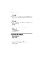
Figure 7.10b: Imported Message Data to Excel
00:31
23:21
22:11
21:01
19:51
18:41
17:31
16:21
15:11
14:01
12:51
11:41
10:31
09:21
08:11
07:01
05:51
04:41
03:31
02:21
01:11
00:01
900
875
850
825
800
775
750
725
700
22:51
Temperature (tenths)
Logged Temperature Data
Time
We set the incubator outside of a window and recorded outdoor temperatures.. Outdoor temperature can be
tricky due to effects of wind cooling, sunlight heating, and thermal layers in the canister trapping heat. We
had quite a few spikes in readings. Can you do better?
Our plot shows temperatures from 22:51 to 22:51 the next night. Note the rise and falls in temperature
during the day. The expected high for the day was 88F, and we came pretty close!
Of course, we are not restricted s temperature range 70F-120F. Refer back to Experiment #4. Software
range values are determined by the span and offset voltage settings to the ADC0831.
TempSpan
Offset
CON
CON
5000
700
Page 218 • Industrial Control Version 1.1
' Full Scale input span (5000 = 50 degrees span)
' Minimum temp. Offset. (700 = 70 degrees)
Experiment #7: Real-time Control and Data Logging
Questions and Challenges:
1. Perform Logging of a System: Determine a temperature that you want to log over a long period of
time. This may be outdoors, the room temperature (does the heating/cooling change during evening
hours?), or maybe some other slow changing system (a water tank in the sun?).
1) Determine the range of expected values for temperature. Set the span and offset variables and
potentiometers appropriately.
2) Determine the length of time you need to collect the data (one day? the weekend?). Based on a
maximum of 50 samples, calculate the interval time needed for logging.
3) Ready to program? If you are going to move your BOE, make sure it is running on a battery that will
last throughout the logging!
4) We also want to check the accuracy of the RTC in this experiment, so when the program is ready to
download:
a) Open the Windows clock and pick an upcoming time.
b) Set the start time to this upcoming time (remember to use 24-hour time)
Time = $1530
c) 5 seconds before the initializing time, download the file to the BS2 and hold the circuit pushbutton down until the LED goes off or debug window instructs you to release it.
d) Use the Debug Window or StampPlot to note the BS2 and the PC Times.
BS2: _________ PC: __________ Difference: ________
e) Let your data record! After the 1st sample is done, you may test the data dump by pressing the
push-button.
f) After you are finished recording data, run and connect StampPlot Lite, press the push-button to
dump the data.
g) Use the Debug Window or StampPlot to note the BS2 and the PC Time.
BS2:_________ PC: __________ Difference: ________
h) Extrapolate the time-error for 24 hours: _________
Did the data conform to your expectations?
Industrial Control Version 1.1 • Page 219
Experiment #7: Real-time Control and Data Logging
2.
Discuss the 'system' you monitored and conclusions of your results.
3. How much time error was calculated over a 24-hour period? How could this error be compensated
for in software?
4. Why is it important to limit the amount of data that can be stored in the BS2?
Page 220 • Industrial Control Version 1.1