Industrial Control Student Guide Version 1.1 phần 9 ppt
Bạn đang xem bản rút gọn của tài liệu. Xem và tải ngay bản đầy đủ của tài liệu tại đây (1014.33 KB, 22 trang )
Appendix A: StampPlot Lite
Appendix A:
StampPlot Lite
StampPlot Lite is an application developed by SelmaWare Solutions for the
Industrial Control series. The application allows plotting and capture of analog,
digital and general data.
Downloading and Installing StampPlot Lite
StampPlot Lite may be downloaded from the Stamps in Class web site at . The
program is installed by double-clicking on the setup.exe icon and accepting the default directories.
To download StampPlot Lite, click on
the “Downloads” button on our web site
and scroll down to the “Industrial
Control” section.
Industrial Control Version 1.1 • Page 221
Appendix A: StampPlot Lite
Data from the BASIC Stamp is processed in one of four ways by the application:
Analog Values
Any string sent beginning with a numeric value will be processed as an analog value and graphed.
Debug DEC 100, 13
'Plot the number 100
Digital Values
Any string sent beginning with '%' will be processed as digital values. A separate digital plot will be started for
each binary value in the string. For example, "%1001" will plot four digital values. Up to a 9-bit value may be
sent. Once digital plots are started, caution should be used to always send the same number of bits since the
plots are position-order dependent.
Debug IBIN4 INC,13
'Plots 4 digital values
Control Settings
Any string beginning with '!' will be processed as a control setting. The various settings of the application may
be controlled from the BASIC Stamp using specified control words and values, if required.
Debug "!AMAX 200",13
Debug "!RSET",13
'Sets analog maximum for plot to 200
'Resets the plot
Other Strings
All other strings simply will be added to the running message list box.
Debug "Hello world!",13
Note that each instance of data MUST end with a carriage return (13 or CR).
Page 222 • Industrial Control Version 1.1
Appendix A: StampPlot Lite
The steps for using BASIC Stamp programs with StampPlot Lite are as follows:
1.
2.
3.
4.
5.
6.
Start StampPlot Lite through your Start/Programs/StampPlot/StampPlot Lite icon.
Enter and run your BASIC Stamp program from the BASIC Stamp editor.
Close the blue BASIC Stamp debug window by clicking on the “close” box.
Select the COM port and click 'Connect' checkbox.
Click the 'Plot Data' checkbox.
Some programs may require you to reset the Board of Education (BASIC Stamp) to catch initial
configuration and control settings. Do this by pressing the Reset button on the board.
7. Prior to downloading (running) another program to the BASIC Stamp, be sure to uncheck the
StampPlot 'Connect' checkbox or your COM port will be locked by StampPlot Lite.
The plot will acquire analog and digital data and store it temporarily so that it may be resized or shifted on
the screen. The number of data points collected is adjustable. Once the data points reach maximum, the plot
must either be stopped or reset.
The following program will perform some configuration settings, continually plot and display the value of X on
StampPlot, and plot the four digital bits of the value of X. Enter the program and use the steps above to test
it with StampPlot Lite.
'Appendix A Program, StampPlot Example
'Configure StampPlot
' Variable for counting
Pause 500: Debug "!RSET",CR
' Short pause and reset
Debug "!SPAN 0, 50",CR
' Span the analog range
Debug "!TSMP ON",CR
' Time Stamp the messages
Debug "!TMAX 60",CR
' Set plot to 60 seconds max
Debug "!RSET",CR
' Reset the plot
X var
Loop:
Debug
For X
Debug
Debug
Byte
"Starting loop", CR
= 0 to 15
DEC X, CR
IBIN4 X, CR
' Message that loop is resetting.
' For-Next loop to count to 15
' Plot Analog value of X
' Plot digital bits of X
' Change the User Status message.
Debug "!USRS The value of X is ", DEC X, CR
Pause 200
' Short pause
Next
Goto Loop
' Restart
Industrial Control Version 1.1 • Page 223
Appendix A: StampPlot Lite
Below is a screen shot of StampPlot Lite showing the above program plotted.
Page 224 • Industrial Control Version 1.1
Appendix A: StampPlot Lite
Tool Text Help
If a copy of StampPlot Lite is running on your computer, you may place the cursor over each control for 'Tool
Text Help.’ The following is a brief summary of each control. The BASIC Stamp programmable command,
where applicable, is in brackets:
Top Section: General Controls
•
•
•
•
•
•
•
Com 1: Drop down to select the applicable COM port.
Connect: Connects the application to the selected COM port.
Plot Data: Allows plotting of incoming data. Deselecting this control will stop the plotting of data but will
allow messages and other actions to continue. [ !PLOT ON/OFF]
Reset: Clears the plot, resets to time 0, clears minimum and maximum value (optional). [ !RSET ]
Stop Plot: When maximum data points are reached, the plot stops (Plot Data becomes unchecked).
[!MAXS ]
Reset Plot: When maximum data points are reached, the plot resets. [ !MAXR ]
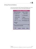
User Status: (showing "The value of X is 9") Optional status messages from the BASIC Stamp may place
data here. [ !USRS message ]
Industrial Control Version 1.1 • Page 225
Appendix A: StampPlot Lite
Left Section: Primarily for Setting the Analog Plot
•
•
•
•
•
•
•
•
•
•
Span Drop-Down box: Allows a selection of pre-defined plot ranges. Use of the
BASIC Stamp command !SPAN will add a range to this drop-down.
[ !SPAN minvalue, maxvalue ]
+ and - buttons: Respectively double or halve the span. The minimum value
does not change.
Multiplier: Defines the amount incoming BASIC Stamp analog data will be
multiplied by prior to plotting or saving to file. [ !AMUL value ]
Save Data to File: Saves the incoming data to a text file in the application
directory called "stampdat.txt.” If time stamping is enabled, each record will be
marked with the current system time and the number of seconds since the last
reset. The value of the data point for analog and digital values will also be
recorded. Each record will have the following form:
- Time of day, seconds since reset, analog data point, analog value, digital
data point, digital data value. Note that each record is comma
delineated for importing into a spreadsheet, if desired.
- Note: Data is saved ONLY when ANALOG data arrives. To force saving
when no analog data is recorded, debug a value such as zero ( DEBUG
DEC 0, CR).[ !SAVD ON/OFF ]
Delete Data File: Deletes "stampdat.txt.” If data saving is enabled, the file will be re-created after
deleting it. [ !DELD ]
Analog Minimum and Maximum values: These may be manually changed. Tab off, or click another
control, to set the new value. [ !AMIN value !AMAX value <or> !SPAN minvalue, maxvalue ]
Time Stamp: Enables time stamping of messages and data to the file. It includes both the current
time and seconds since the last reset. [ !TSMP ON/OFF ]
Clear Messages: Clears the messages in the listbox. [ !CLRM ]
Save messages to file: Saves messages to the file "stampmsg.txt" in the application directory.
Messages will be saved the same way they appear in the message box. [ !SAVM ON/OFF ]
Delete Msg file: Deletes "stampmsg.txt" in the application directory. If the "Save Messages…" is
enabled, the file will be re-created. [ !DELM ]
Page 226 • Industrial Control Version 1.1
Appendix A: StampPlot Lite
Bottom Section: Plot Shift and Time Span
•
•
•
•
The minimum and maximum times of the plot may be set manually. Tab-off or click another control
to apply the value. [ !TMIN value and !TMAX value ]
Scroll Bar: If the plot extends beyond the current limits, the scroll bar may be used to reposition the
plot (if collecting data, Enable Shift must be on).
Enable Shift: Allows the plot to shift automatically when maximum plotted time is exceeded. Also
enables operation of the scroll bar when collecting data. Note: Shifting of the plot during data
collection may cause time errors in the data as the plot refreshes. [ !SHFT ON/OFF ]
+/-: Respectively doubles or halves the time span of the plot. The minimum value of the plot will not
change.
Right Section: Plot Data
•
•
•
•
•
•
•
Data Points: To allow the plot to be manipulated, data is stored in memory.
The maximum number of points (either analog or digital) that may be
recorded is the Max. ‘Current’ displays the current data point being stored.
Once the maximum is reached, the plot will either reset or stop, depending
on the configuration. [ !PNTS 1000 ]
Last Analog Data: Displays the time since reset and the last analog value
plotted.
Plot Pointer: Moving the plot pointer on the display shows the current
analog value and time for that point on the plot.
Maximum: Records the maximum analog value and the time it was reached.
Minimum: Records the minimum analog value and the time it was reached.
Clear Min/Max: Clears the recorded minimum and maximum values. [ !CLMM
]
Clear min/max on reset: Allows a reset to clear the minimum and maximum
values. [!CMMR]
Industrial Control Version 1.1 • Page 227
Appendix A: StampPlot Lite
Page 228 • Industrial Control Version 1.1
Appendix A: StampPlot Lite
Display Control and Zoom
•
•
•
Moving the cursor on the plot will set the plot pointer time and value to the current position.
Double-clicking the plot will shift display modes from yellow to white background and thin lines to
thick lines for better printing (ALT-Print Screen to capture form to the clipboard) and projected
display.
Shift-Click (hold) and Drag allows you to specify an area of the plot to zoom.
BASIC Stamp Control and Configuration Commands
The majority of the plot configuration and controls may be set from within the BASIC Stamp program. To use
these commands, simply debug from the BASIC Stamp. All commands must end with a CR (ASCII 13): DEBUG
"!PLOT ON", CR.
Command
!TITL message
!USRS message
!BELL
!AMAX value
!AMIN value
!SPAN minValue,
maxValue
!AMUL value
!TMAX value
!TMIN value
!PNTS value
!PLOT ON/OFF
!RSET
!CLRM
!CLMM
!CMMR ON/OFF
!MAXS
!MAXR
!SHFT ON/OFF
!TSMP ON/OFF
!SAVD ON/OFF
!SAVM ON/OFF
!DELD
!DELM
Description
Sets the title of the form to the message
Sets the User Status box to display the message
Sounds the bell on the PC
Sets the plot maximum analog value
Sets the plot minimum analog value
Sets the plots analog maximum and minimum as above (also adds the range to
the Range Drop-Down box).
Sets the value to multiply incoming data by
Sets the plot maximum time (seconds)
Sets the plot minimum time (seconds)
Sets the number of data points to collect
Enables/disables the plotting of data
Resets the plot and all data
Clears the message list
Clears the min/max recorded values
Enables/Disables clearing of Min/Max recorded values on reset
Sets the plot to STOP when data points are full
Sets the plot to RESET when data points are full
Enables/disables the plot from shifting when recording data (may cause a loss
of data accuracy if enabled)
Enables time stamping of list messages; messages and data saved to files
Enables saving of analog and digital data to files
Enables saving of messages to a file
Deletes the saved data file
Deletes the saved message file
Industrial Control Version 1.1 • Page 229
Appendix A: StampPlot Lite
Additional Application Notes
The amount of the plot that is used is dependent on the number of data points and the rate at which they are
transmitted. For example, if you wish 60 seconds of data to fill the screen and are transmitting from the
BASIC Stamp at a maximum rate of 100 msec (Pause 100 + processing time): 60/.1 = 600 data points.
The application needs a minimum regular pause in the reception of data for complete processing. A pause of
10 msec is typically sufficient for a fairly fast computer. If the application senses it cannot keep up with
incoming data, a message box will appear and the application will disconnect. Some indications that the
computer cannot keep up are: garbled data, no plotting, and the inability to affect any controls (locks up).
The greater the number of data points and the higher the current data point, the longer the plot will take to
respond to plot shifts as it redraws. For faster, reliable configuration from the BASIC Stamp on initial power
up or resetting, the following is recommended:
•
•
•
Pause for 500msec at the start to allow StampPlot's buffer to clear.
Perform a StampPlot RESET (!RSET) prior to making configuration changes to allow the data points to
be cleared so redrawing is not performed.
Reset (!RSET) at the end of the configuration resets the plot to time 0.
As with any application, the best way to learn it is to play. Have fun!
Page 230 • Industrial Control Version 1.1
Appendix A: StampPlot Lite
Upgrade to StampPlot Pro for your Industrial Control experiments!
A few of the features include:
• Plotting of multiple analog channels.
• Saving of plots and images.
• Advanced logging features.
• Ability to draw graphics.
• PC based macros of instructions, including data manipulation.
• Interactive capabilities for adjustments on the fly.
This screen shot of StampPlot Pro shows the PID exercise in Experiment #7 plotting actual and setpoint
temperature along with the %Drive (bottom bars).
The gain values may be
entered in the data
window to be read by your
BS2!
A PC based macro shows
the temperature in the
thermometer.
Examples based on the
Industrial Control text are
posted in the on-line
tutorials. Download and
evaluate free!
m/
Industrial Control Version 1.1 • Page 231
Appendix A: StampPlot Lite
Page 232 • Industrial Control Version 1.1
Appendix B: Fan Encoder Printouts
Appendix B:
Fan Encoder Printouts
These printouts are full size, and should be an
ideal fit for your fan used as a digital switch in
Experiment #2.
Industrial Control Version 1.1 • Page 233
Appendix B: Fan Encoder Printouts
Page 234 • Industrial Control Version 1.1
Appendix C: Potter Brumfield SSR Datasheet
Appendix C:
Potter Brumfield SSR
Datasheet
Appendix C consists of the Potter Brumfield “Hockey Puck” Solid State Relay. Their datasheets may be
downloaded from />
Industrial Control Version 1.1 • Page 235
Appendix C: Potter Brumfield SSR Datasheet
Page 236 • Industrial Control Version 1.1
Appendix C: Potter Brumfield SSR Datasheet
Industrial Control Version 1.1 • Page 237
Appendix C: Potter Brumfield SSR Datasheet
Page 238 • Industrial Control Version 1.1
Appendix D: LM34 Manufacturer’s Datasheet
Appendix D:
National Semiconductor
LM34 Datasheet
Appendix D consists of the National Semiconductor LM34 datasheet. This appendix includes the first five (5)
pages of the 12-page datasheet. Should you wish to see more applications of the LM34 than are shown in this
datasheet, the entire document may be downloaded from />
Industrial Control Version 1.1 • Page 239
Appendix D: LM34 Manufacturer’s Datasheet
Page 240 • Industrial Control Version 1.1
Appendix D: LM34 Manufacturer’s Datasheet
Industrial Control Version 1.1 • Page 241
Appendix D: LM34 Manufacturer’s Datasheet
Page 242 • Industrial Control Version 1.1