MEMORY, MICROPROCESSOR, and ASIC phần 5 potx
Bạn đang xem bản rút gọn của tài liệu. Xem và tải ngay bản đầy đủ của tài liệu tại đây (1.16 MB, 42 trang )
6-15Dynamic Random Access Memory
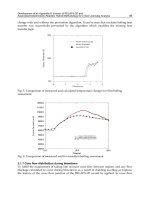
6.9.3 Charge-Coupling Sensing
Figure 6.18 shows the charge in bit-line levels due to coupling capacitor C
c
. The MSB is sensed using
the reference level of half-V
cc
, as mentioned earlier. The MSB generates the reference level for LSB
sensing. When V
s
is defined as the absolute signal level of data “11” and “00”, the absolute signal level of
data “10” and “01” is one-third of V
s
. Here, V
s
is directly proportional to the ratio between storage
capacitor C
s
and bit-line capacitance.
In the case of sensing data “11”, the initial signal level is V
s
. After MSB sensing, the bit-line level in
Section B is changed for LSB sensing by the MSB through coupling capacitor C
c
. The reference bit-
line in Section B is raised by V
c
, and the other bit-line is reduced by V
c
. For LSB sensing, V
c
is one-third
of V
s
due to the coupling capacitor C
c
.
Using the two-step sensing scheme, the 2-bit data in a DRAM cell can be implemented.
References
1. Sekiguchi., T. et al., “An Experimental 220MHz 1Gb DRAM,” ISSCC Dig. Tech. Papers, pp. 252–253,
Feb. 1995.
2. Sugibayashi, T. et al., “A 1Gb DRAM for File Applications,” ISSCC Dig. Tech. Papers, pp. 254–255, Feb.
1995.
3. Murotani, T. et al., “A 4-Level Storage 4Gb DRAM,” ISSCC Dig. Tech. Papers, pp. 74–75, Feb. 1997.
4. Furuyama, T. et al., “An Experimental 2-bit/Cell Storage DRAM for Macrocell or Memory-on-Logic
Application,” IEEE J. Solid-State Circuits, vol. 24, no. 2, pp. 388–393, April 1989.
5. Ahlquist, C.N. et al., “A 16k 384-bit Dynamic RAM,” IEEE J. Solid-State Circuits, vol. SC-11, no. 3, Oct.
1976.
TABLE 6.2 Charge-Sharing Restore Scheme
FIGURE 6.18 Charge-coupling sensing.
6-16 Memory, Microprocessor, and ASIC
6. El-Mansy, Y. et al., “Design Parameters of the Hi-C SRAM cell,” IEEE J. Solid-State Circuits, vol. SC-17,
no. 5, Oct. 1982.
7. Lu, N.C. C., “Half-V
DD
Bit-Line Sensing Scheme in CMOS DRAM’s,” IEEE J. Solid-State Circuits, vol.
SC-19, no. 4, Aug. 1984.
8. Lu, N.C. C., “Advanced Cell Structures for Dynamic RAMs,” IEEE Circuits and Devices Magazine, pp.
27–36, Jan. 1989.
9. Mashiko, K. et al., “A 4-Mbit DRAM with Folded-Bit-Line Adaptive Sidewall-Isolated Capacitor
(FASIC) Cell,” IEEE J. Solid-State Circuits, vol. SC-22, no. 5, Oct. 1987.
10. Prince, B. et al., “Synchronous Dynamic RAM,” IEEE Spectrum, p. 44, Oct. 1992.
11. Yoo, J H. et al., “A 32-Bank 1Gb DRAM with 1GB/s Bandwidth,” ISSCC Dig. Tech. Papers, pp. 378–
379, Feb. 1996.
12. Nitta, Y. et al., “A 1.6GB/s Data-Rate 1Gb Synchronous DRAM with Hierarchical Square-Shaped
Memory Block and Distributed Bank Architecture,” ISSCC Dig. Tech. Papers, pp. 376–377, Feb.
1996.
13. Yoo, J H. et al., “A 32-Bank 1 Gb Self-Strobing Synchronous DRAM with 1 Gbyte/s Bandwidth,”
IEEE J. Solid-State Circuits, vol. 31, no. 11, pp. 1635–1644, Nov. 1996.
14. Saeki, T. et al., “A 2.5-ns Clock Access, 250-MHz, 256-Mb SDRAM with Synchronous Mirror
Delay,” IEEE J. Solid-State Circuits, vol. 31, no. 11, pp. 1656–1668, Nov. 1996.
15. Choi, Y. et al., “16Mb Synchronous DRAM with 125Mbyte/s Data Rate,” IEEE J. Solid-State Circuits,
vol. 29, no. 4, April 1994.
16. Sakashita, N. et al., “A 1.6GB/s Data-Rate 1-Gb Synchronous DRAM with Hierarchical Square
Memory Block and Distributed Bank Architecture,” IEEE J. Solid-State Circuits, vol. 31, no. 11, pp.
1645–1655, Nov. 1996.
17. Okuda, T. et al., “A Four-Level Storage 4-Gb DRAM,” IEEE J. Solid-State Circuits, vol. 32, no. 11, pp.
1743–1747, Nov. 1997.
18. Prince, B., Semiconductor Memories, 2nd edition, John Wiley & Sons, 1993.
19. Prince, B., High Performance Memories New Architecture DRAMs and SRAMs Evolution and Function, 1st
edition, Betty Prince, 1996.
20. Toshiba Applications Specific DRAM Databook, D-20, 1994.
7-1
7
Low-Power Memory
Circuits
7.1 Introduction 7-1
7.2 Read-Only Memory (ROM) 7-2
Sources of Power Dissipation
Low-Power ROMs
7.3 Flash Memory 7-4
Low-Power Circuit Techniques for Flash Memories
7.4 Ferroelectric Memory (FeRAM) 7-8
7.5 Static Random-Access Memory (SRAM) 7-14
Low-Power SRAMs
7.6 Dynamic Random-Access Memory (DRAM) 7-25
Low-Power DRAM Circuits
7.7 Conclusion 7-35
7.1 Introduction
In recent years, rapid development in VLSI fabrication has led to decreased device geometries and
increased transistor densities of integrated circuits, and circuits with high complexities and very high
frequencies have started to emerge. Such circuits consume an excessive amount of power and generate
an increased amount of heat. Circuits with excessive power dissipation are more susceptible to run-
time failures and present serious reliability problems. Increased temperature from high-power processors
tends to exacerbate several silicon failure mechanisms. Every 10°C increase in operating temperature
approximately doubles a component’s failure rate. Increasingly expensive packaging and cooling strategies
are required as chip power increases.
1,2
Due to these concerns, circuit designers are realizing the
importance of limiting power consumption and improving energy efficiency at all levels of design. The
second driving force behind the low-power design phenomenon is a growing class of personal computing
devices, such as portable desktops, digital pens, audio-and video-based multimedia products, and
wireless communications and imaging systems, such as personal digital assistants, personal communicators,
and smart cards. These devices and systems demand high-speed, high-throughput computations, complex
functionalities, and often real-time processing capabilities.
3,4
The performance of these devices is limited
by the size, weight, and lifetime of batteries. Serious reliability problems, increased design costs, and battery-
operated applications have prompted the IC design community to look more aggressively for new approaches and
methodologies that produce more power-efficient designs, which means significant reductions in power consumption for
the same level of performance.
Memory circuits form an integral part of every system design as dynamic RAMs, static RAMs,
ferroelectric RAMs, ROMs, or Flash memories significantly contribute to system-level power
consumption. Two examples of recently presented reduced-power processors show that 43% and
50.3%, respectively, of the total system power consumption is attributed to memory circuits.
5,6
Therefore,
reducing the power dissipation in memories can significantly improve the system power-efficiency,
performance, reliability, and overall costs.
0-8493-1737-1/03/$0.00+$1.50
© 2003 by CRC Press LLC
Martin Margala
University of Alberta
7-2 Memory, Microprocessor, and ASIC
In this chapter, all sources of power consumption in different types of memories will be identified;
several low-power techniques will be presented; and the latest developments in low-power memories
will be analyzed.
7.2 Read-Only Memory (ROM)
ROMs are widely used in a variety of applications (permanent code storage for microprocessors or
data look-up tables in multimedia processors) for fixed long-term data storage. The high area density
and new submicron technologies with multiple metal layers increase the popularity of ROMs for a
low-voltage, low-power environment. In the following section, sources of power dissipation in ROMs
and applicable efficient low-power techniques are examined.
7.2.1 Sources of Power Dissipation
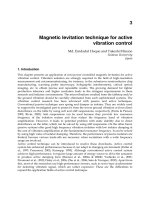
A basic block diagram of a ROM architecture is presented in Fig. 7.1.
7,8
It consists of an address
decoder, a memory controller, a column multiplexer/driver, and a cell array. Table 7.1 lists an example of
a power dissipation in a 2 K×18 ROM designed in 0.6-µm CMOS technology at 3.3 V and clocked at
10 MHz.
8
The cell array dissipates 89% of the total ROM power, and 11% is dissipated in the decoder,
control logic, and the drivers. The majority of the power consumed in the cell array is due to the
precharging of large capacitive bit-lines. During the read and write cycles, more than 18 bit-lines are
switched per access because the word-line selects more bit-lines than necessary. The example in Fig. 7.2
shows a 12–1 multiplexer and a bit-line with five transistors connected to it. This topology consumes
excessive amounts of power because 4 more bit-lines will switch instead of just one. The power
dissipated in the decoder, control logic, and drivers is due to the switching activity during the read and
precharge cycles and generating control signals for the entire memory
7.2.2 Low-Power ROMs
In order to significantly reduce the power consumption in ROMs, every part of the architecture has to
be targeted and multiple techniques have to be applied. De Angel and Swartzlander
8
have identified
several architectural improvements in the cell array that minimize energy waste and improve efficiency.
These techniques include:
FIGURE 7.1 Basic ROM architecture. (© 1997, IEEE. With permission.)
7-3Low-Power Memory Circuits
• Hierarchical word-line
• Selective precharging
• Minimization of non-zero terms
• Inverted ROM core(s)
• Row(s) inversion
• Sign magnitude encoding
• Sign magnitude and inverted block
• Difference encoding
• Smaller cell arrays
All of these methods result in a reduction of the capacitance and/or switching activity of bit- and row-
lines. A hierarchical word-line approach divides memory into separate blocks and runs the block word-
line in one layer and a global word-line in another layer. As a result, only the bit cells of the desired
block are accessed. A selective precharging method addresses the problem of activating multiple bit-lines,
although only a single memory location is being accessed. By using this method, only those bit-lines
that are being accessed are precharged. The hardware overhead for implementing this function is
minimal. A minimization of non-zero terms reduces the total capacitance of bit- and row-lines because
zero-terms do not switch bit-lines. This also reduces the number of transistors in the memory core. An
inverted ROM applies to a memory with a large number of 1s. In this case, the entire ROM array could
be inverted and the final data will be inverted back in the output driver circuitry. Consequently, the
number of transistors and the capacitance of bit- and row-lines are reduced. An inverted row method
also minimizes non-zero terms, but on a row-by-row basis. This type of encoding requires an extra bit
(MSB) that indicates whether or not a particular row is encoded. A sign and magnitude encoding is used
to store negative numbers. This method also minimizes the number of 1s in the memory. However, a
two’s complement conversion is required when data is retrieved from the memory. A sign and magnitude
and an inverted block is a combination of the two techniques described previously. A difference encoding can
be used to reduce the size of the cell array. In applications where a ROM is accessed sequentially and
the data read from one address does not change significantly from the following address, the memory
TABLE 7.1 Power Dissipation ROM 2 K×18
(Source: © 1997, IEEE. With permission.)
FIGURE 7.2 ROM bit-lines. (© 1997, IEEE. With permission.)
7-4 Memory, Microprocessor, and ASIC
core can store the difference between these two entries instead of the entire value. The disadvantage
is a need for an additional adder circuit to calculate the original value. In applications where different
bit sizes of data are needed, smaller memory arrays are useful to implement. If stored in a single memory
array, its bit size is determined by the largest number. However, most of the bit positions in smaller
numbers are occupied by non-zero values that would increase the bit-line and row-line capacitance.
Therefore, by grouping the data to smaller memory arrays according to their size, significant savings in
power can be achieved.
On the circuit level, powerful techniques that minimize the power dissipation can be applied. The most
common technique is reducing the power supply voltage to approximately in a correlation with
the architectural-based scaling. In this region of operation, the CMOS circuits achieve the maximum power
efficiency.
9,10
This results in large power savings because the power supply is a quadratic term in a well-
known dynamic power equation. In addition, the static power and short-circuit power are also reduced. It is
important that all the transistors in the decoder, control logic, and driver block be sized properly for low-
power, low-voltage operation. Rabaey and Pedram
9
have shown that the ideal low-power sizing is when
C
d
=C
L
/2, where C
d
is the total parasitic capacitance from driving transistors and C
L
is the total load capacitance
of a particular circuit node. By applying this method to every circuit node, a maximum power efficiency can
be achieved. Third, different logic styles should be explored for the implementation of the decoder, control
logic, and drivers. Some alternative logic styles are superior to standard CMOS for low-power, low-voltage
operation.
11,12
Fourth, by reducing the voltage swing of the bit-lines, significant reduction in switching
power can be obtained. One way of implementing this technique is to use NMOS precharge transistors.
The bit-lines are then precharged to V
dd
—V
t
. A fifth method can be applied in cases when the same
location is accessed repeatedly.
8
In this case, a circuit called a voltage keeper can be used to store past history
and avoid transitions in the data bus and adder (if sign and magnitude is implemented). The sixth method
involves limiting short-circuit dissipation during address decoding and in the control logic and drivers. This
can be achieved by careful design of individual logic circuits.
7.3 Flash Memory
In recent years, flash memories have become one of the fastest growing segments of semiconductor
memories.
13,14
Flashmemories are used in a broad range of applications, such as modems, networking
equipment, PC BIOS, disk drives, digital cameras, and various new microcontrollers for leading-edge
embedded applications. They are primarily used for permanent mass data storage. With the rapidly
emerging area of portable computing and mobile telecommunications, the demand for low-power,
low-voltage flash memories increases. Under such conditions, flash memories must employ low-power
tunneling mechanisms for both write and erase operations, thinner tunneling dielectrics, and on-chip
voltage pumps.
7.3.1 Low-Power Circuit Techniques for Flash Memories
In order to prolong the battery life in mobile devices, significant reductions of power consumption in
all electronic components have to be achieved. One of the fundamental and most effective methods is
a reduction in power supply voltage. This method has also been observed in Flash memories. Designs
with a 3.3-V power supply, as opposed to the traditional 5-V power supply, have been reported.
15–20
In
addition, multi-level architectures that lower the cost per bit, increase memory density, and improve
energy efficiency per bit, have emerged.
17,20
Kawahara et al.
22
and Otsuka and Horowitz
23
have identified
major bottlenecks when designing Flash memories for low-power, low-voltage operation and proposed
suitable technologies and techniques for deep sub-micron, sub-2V power supply Flash memory design.
Due to its construction, a Flash memory requires high voltage levels for program and erase operations,
often exceeding 10 V (V
pp
). The core circuitry that operates at these voltage levels cannot be as
aggressively scaled as the peripheral circuitry that operates with standard V
dd
. Peripheral devices are
7-5Low-Power Memory Circuits
designed to improve the power and performance of the chip, whereas core devices are designed to
improve the read performance. Parameters such as the channel length, the oxide thickness, the threshold
voltage, and the breakdown voltage must be adjusted to withstand high voltages. Technologies that
allow two different transistor environments on the same substrate must be used. An example of transistor
parameters in a multi-transistor process is given in Table 7.2.
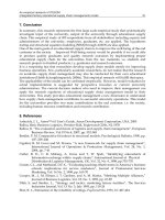
Technologies reaching deep sub-micron levels—0.25 µm and lower—can experience three major
problems (summarized in Fig. 7.3): (1) layout of the peripheral circuits due to a scaled Flash memory
cell; (2) an accurate voltage generation for the memory cells to provide the required threshold voltage
and narrow deviation; and (3) deviations in dielectric film characteristics caused by large numbers of
memory cells. Kawahara et al.
22
have proposed several circuit enhancements that address these problems.
They proposed a sensing circuit with a relaxed layout pitch, bit-line clamped sensing multiplex, and
intermittent burst data transfer for a three times feature-size pitch. They also proposed a low-power
dynamic bandgap generator with voltage boosted by using triple-well bipolar transistors and voltage-
doubler charge pumping, for accurate generation of 10 to 20 V that operate at V
dd
under 2.5 V. They
demonstrated these improvements on a 128-Mb experimental chip fabricated using 0.25-µm technology.
On the circuit level, three problems have been identified by Otsuka and Horowitz:
23
(1) interface
between peripheral and core circuitry; (2) sense circuitry and operation margin; and (3) internal high
voltage generation.
TABLE 7.2 Transistor Parameters
Source: © 1997, IEEE. With permission.
FIGURE 7.3 Quarter-micron flash memory. (© 1996, IEEE. With permission.)
7-6 Memory, Microprocessor, and ASIC
During program and erase modes, the core circuits are driven with higher voltage than the peripheral
circuits. This voltage is higher than V
dd
in order to achieve good read performance. Therefore, a level-
shifter circuit is necessary to interface between the peripheral and core circuitry. However, when a
standard power supply (V
dd
) is scaled to 1.5 V and lower, the threshold voltage of V
pp
transistors will
become comparable to one half of V
dd
or less, which results in significant delay and poor operation
margin of the level shifter and, consequently, degrades the read performance. A level shifter is necessary
for the row decoder, column selection, and source selection circuit. Since the inputs to the level
shifters switch while V
pp
is at the read V
pp
level, the performance of the level shifter needs to be
optimized only for a read operation. In addition to a standard erase scheme, Flash memories utilizing a
negative-gate erase or program scheme have been reported.
15,19
These schemes utilize a single voltage
supply that results in lower power consumption. The level shifters in these Flash memories have to shift
a signal from V
dd
to V
pp
and from Gnd to V
bb
. Conventional level shifters suffer from delay degradation
and increased power consumption when driven with low power supply voltage. There are several
reasons attributed to these effects. First, at low V
dd
(1.5 V), the threshold voltage of V
pp
transistors is close
to half the power supply voltage, which results in an insufficient gate swing to drive the pull-down
transistors as shown in Fig. 7.4. This also reduces the operation margin of these shifters for the threshold
voltage fluctuation of the V
pp
transistor. Second, a rapid increase in power consumption at V
dd
under 1.5
V is due to dc current leakage through V
pp
to Gnd during the transient switching. At 1.5 V, 28% of the
total power consumption of V
pp
is due to dc current leakage. Two signal shifting schemes have been
proposed: one for a standard flash memory and another for a negative-gate erase or program Flash
memories. The first proposed design is shown in Fig. 7.5. This high-level shifter uses a bootstrapping
switch to overcome the degradation due to a low input gate swing and improves the current driving
capability of both pull-down drivers. It also improves the switching delay and the power consumption
at 1.5 V because the bootstrapping reduces the dc current leakage during the transient switching.
FIGURE 7.4 Conventional high-level shifter circuits with (a) feedback pMOS and (b) cross-coupled pMOS. (©
1997, IEEE. With permission.)
7-7Low-Power Memory Circuits
Consequently, the bootstrapping technique increases the operation margin. The layout overhead from
the bootstrapping circuit, capacitors, and an isolated n-well is negligible compared to the total chip area
because it is used only as the interface between the peripheral circuitry and the core circuitry. Figure
7.6 shows the operation of the proposed high-level shifter, and Fig. 7.7 illustrates the switching delay
and the power consumption versus the power supply voltage of the conventional design and the
FIGURE 7.5 A high-level shifter circuit with bootstrapping switch. (© 1997, IEEE. With permission.)
FIGURE 7.6 Operation of the proposed high-level shifter circuit. (© 1997, IEEE. With permission.)
7-8 Memory, Microprocessor, and ASIC
proposed design. The second proposed design, shown in Fig. 7.8, is a high/low-level shifter that also
utilizes a bootstrapping mechanism to improve the switching speed, reduce dc current leakage, and
improve operation margin. The operation of the proposed shifter is illustrated in Fig. 7.9. At 1.5 V, the
power consumption decreases by 40% compared to a conventional two-stage high/low-level shifter, as
shown in Fig. 7.10. The proposed level shifter does not require an isolated n-well and therefore the
circuit is suitable for a tight-pitch design and a conventional well layout. In addition to the more
efficient level-shift scheme, Otsuka and Horowitz
23
also addressed the problem of sensing under very
low power supply voltages (1.5 V) and proposed a new self-bias bit-line sensing method that reduces
the delay’s dependence on bit-line capacitance and achieves a 19-ns reduction of the sense delay at
low voltages. This enhances the power efficiency of the chip.
On a system level, Tanzawa et al.
25
proposed an on-chip error correcting circuit (ECC) with only
2% layout overhead. By moving the ECC from off-chip to on-chip, 522-Byte temporary buffers that are
required for conventional ECC and occupy a large part of ECC area, have been eliminated. As a result,
the area of ECC circuit has been reduced by a factor of 25. The on-chip ECC has been optimized,
which resulted in an improved power-efficiency by a factor of two.
7.4 Ferroelectric Memory (FeRAM)
Ferroelectric memory combines the advantages of a non-volatile Flash memory and the density and
speed of a DRAM memory. Advances in low-voltage, low-power design toward mobile computing
applications have been seen in the literature.
28,29
Hirano et al.
28
reported a new 1-transistor/1-capacitor
nonvolatile ferroelectric memory architecture that operates at 2 V with 100-ns access time. They
achieved these results using two new improvements: a bit-line-driven read scheme and a non-relaxation
reference cell. In previous ferroelectric architectures, either a cell-plate-driven or non-cell-plate driven
read scheme, as shown in Figs. 7.11(a) and (b), was used.
30,31
Although the first architecture could
operate at low supply voltages, the large capacitance of the cell plate, which connects to many ferroelectric
capacitors and a
FIGURE 7.7 Comparison between proposed and conventional high-level shifters. (© 1997, IEEE. With permission.)
7-9Low-Power Memory Circuits
large parasitic capacitor, would degrade the performance of the read operation due to large
transient time necessary to drive the cell plate. The second architecture suffers from two problems.
The first problem is the risk of losing the data stored in the memory due to the leakage current
of a capacitor. The storage node of a memory cell is floating and the parasitic p-n junction
between the storage node and the substrate leaks the current. Consequently, the storage node
reaches the V
ss
level and another node of the capacitor is kept at 1/2 V
dd
, which causes the data
destruction. Therefore, this scheme requires a refresh operation of memory cell data. The second
FIGURE 7.8 Proposed high/low-level shifter circuit. (© 1997, IEEE. With permission.)
FIGURE 7.9 Operation of the proposed high/low-level shifter circuit. (© 1997, IEEE. With permission.)
7-10 Memory, Microprocessor, and ASIC
problem arises from a low-voltage operation. Due to a voltage across the memory cell capacitor
being at 1/2 V
dd
under this scheme, the supply voltage must be twice as high as the coercive
voltage of ferroelectric capacitors, which prevents the low-voltage operation. To overcome these
problems, Hirano et al.
28
have developed a new bit-line-driven read scheme which is shown in
Figs. 7.12 and 7.13. The bit-line-driven circuit precharges the bit-lines to supply V
dd
voltage. The
cell plate line is fixed at ground voltage in the read operation. An important characteristic of this
configuration is that the bit-lines are driven, while the cell plate is not driven. Also, the precharged
voltage level of the bit-lines is higher than that of the cell plate. Figure 7.14 shows the limitations
of previous schemes and the new scheme. During the read operation, the first previously
presented scheme
30
requires a long delay time to drive the cell plate line. However, the proposed
scheme exhibits faster transient response because the bit-line capacitance is less than 1/100 of the
cell plate-line capacitance. The second previously presented scheme
31
requires a data refresh
operation in order to secure data retention. The read scheme proposed by Hirano et al.
28
does not
require any refresh operation since the cell plate voltage is at 0 V during the stand-by mode.
The reference voltage generated by a reference cell is a critical aspect of a low-voltage operation of
ferroelectric memory. The reference cell is constructed with one transistor and one ferroelectric
capacitor. While a voltage is applied to the memory cell to read the data, the bit-line voltage reading
from the reference cell is set to about the midpoint of “H” and “L” which are read from the main-
memory-cell data. The state of the reference cell is set to “Ref” as shown at the left side of Fig. 7.15.
However, a ferroelectric capacitor suffers from the relaxation effect, which decreases the polarization as
shown at the right side of Fig.7.15. As a result, each state of the main memory cells and the reference
cell is shifted, and the read operation of “H” data is marginal and prohibits the scaling of power supply
voltage. Hirano et al.
28
have developed a reference cell that does not suffer from a relaxation effect,
moves always along the curve from the “Ref” point, and therefore enlarges the read operation margin
for “H” data. This proposed scheme enables a low-voltage operation down to 1.4 V.
FIGURE 7.10 Comparison between proposed and conventional high/low-level shifters. (© 1997, IEEE. With
permission.)
7-11Low-Power Memory Circuits
FIGURE 7.11 (a) Cell-plate-driven read scheme, and (b) non-cell-plate-driven read scheme. (© 1997, IEEE.
With permission.)
FIGURE 7.12 Memory cell array architecture. (© 1997, IEEE. With permission.)
7-12 Memory, Microprocessor, and ASIC
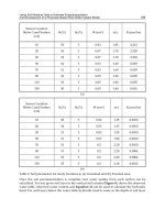
Fujisawa et al.
29
addressed the problem of achieving high-speed and low-power operation in ferro-
electric memories. Previous designs suffered from excessive power dissipation due to the need of a
refresh cycle
30,31
because of the leak age current from a capacitor storage node to the substrate where
the cell plates are fixed to 1/2 V
dd
. Figure 7.16 shows a comparison of the power dissipation between
ferroelectric memories (FeRAMs) and DRAMs. It can be observed that the power consumption of
peripheral circuits is identical, but the power consumption of memory array sharply increases in the 1/
2 V
dd
plate FeRAMs. These problems can be summarized as follows:
FIGURE 7.13 Memory cell and peripheral circuit with bit-line-driven read scheme. (© 1997, IEEE. With
permission.)
FIGURE 7.14 Limitations of previous schemes and proposed solutions. (© 1997, IEEE. With permission.)
FIGURE 7.15 Reference cell proposed by Sumi et al. in Ref. 30. (© 1997, IEEE. With permission.)
7-13Low-Power Memory Circuits
• The memory cell capacitance is large and therefore the capacitance of the data-line needs to be
set larger in order to increase the signal voltage of non-volatile data.
• The non-volatile data cannot be read by the 1/2 V
dd
subdata-line precharge technique because
the cell plate is set to 1/2 V
dd
. Therefore, the data-line is precharged to V
dd
or Gnd.
When the memory cell density rises, the number of activated data-lines increases. This increases power
dissipation of the array. A selective subdata-line activation technique as shown in Fig. 7.17, which was
proposed by Hamamoto et al., overcomes this problem. However, its access time is slower compared to
all-subdataline activation because the selective subdataline activation requires a preparation time. Therefore,
neither of these two techniques can simultaneously achieve low-power and high-speed operation.
Fujisawa et al.
29
demonstrated a low-power high-speed FeRAM operation using an improved charge-
share modified (CSM) precharge-level architecture. The new CSM architecture solves the problems of
slow access speed and high power dissipation. This architecture incorporates two features that reduce
the sensing period, as shown in Fig. 7.18. The first feature is the charge-sharing between the parasitic
capacitance of the main data-line (MDL) and the subdata-line (SDL). During the stand-by mode, all
SDLs and MDLs are precharged to 1/2 V
dd
and V
dd
, respectively. During the read operation, the
precharge circuits are all cut off from the data-lines (time t
0
). After the y-selection signal (YS) is
activated (time t
1
), the charge in the parasitic capacitance of the MDL (C
mdl
) is transferred to the
selected parasitic capacitance of the SDL (C
sdl
) and the selected SDL potential is raised by charge-
sharing. As a result, the voltage is applied only to a memory cell intersecting selected word-line (WL)
and YS. The second feature is a simultaneous activation of WL and YS without causing a loss of the
FIGURE 7.16 Comparison of the power dissipation between FeRAMs and DRAMs. (© 1997, IEEE. With
permission.)
FIGURE 7.17 Low power dissipation techniques. (© 1997, IEEE. With permission.)
7-14 Memory, Microprocessor, and ASIC
readout voltage. During the write operation, only data of the selected memory cell is written, whereas
all the other memory cells keep their non-volatile data.
Consequently, the power dissipation does not increase during this operation. The writing period is
equal to the sensing period because WL and YS can also be activated simultaneously in the write cycle.
7.5 Static Random-Access Memory (SRAM)
SRAMs have experienced a very rapid development of low-power, low-voltage memory design during
recent years due to an increased demand for notebooks, laptops, hand-held communication devices,
and IC memory cards. Table 7.3 summarizes some of the latest experimental SRAMs for very low-
voltage and low-power operation
In this section, active and passive sources of power dissipation in SRAMs will be discussed and
common low-power techniques will be analyzed.
7.5.1 Low-Power SRAMs
Sources of SRAM Power
There are different sources of active and stand-by (data retention) power present in SRAMs. The active
power is the sum of the power consumed by the following components:
FIGURE 7.18 Principle of the CSM architecture. (© 1997, IEEE. With permission.)
TABLE 7.3 Low-Power SRAMs Performance Comparison
7-15Low-Power Memory Circuits
• Decoders
• Memory array.
• Sense amplifiers
• Periphery (I/O circuitry, write circuitry, etc.) circuits
The total active power of an SRAM with m×n array of cells can be summarized by the expression
9,33,34
:
(7.1)
where i
active
is the effective current of selected cells, i
leak
is the effective data retention current of the
unselected memory cells, C
DE
is the output node capacitance of each decoder, V
INT
is the internal
power supply voltage, i
DC
is the dc current consumed during the read operation, At is the activation
time of the dc current consuming parts (i.e., sense amplifiers), f is the operating frequency, C
PT
is the
total capacitance of the CMOS logic and the driving circuits in the periphery, and I
DCP
is the total
static (dc) or quasi-static current of the periphery. Major sources of I
DCP
are column circuitry and
differential amplifiers on the I/O lines.
The stand-by power of an SRAM has a major source represented by ileakmn because the static
current from other sources is negligibly small (sense amplifiers are disabled during this mode). Therefore,
the total stand-by power can be expressed as:
(7.2)
Techniques for Low-Power Operation
In order to significantly reduce the power consumption in SRAMs, all contributors to the total power
must be targeted. The most efficient techniques used in recent memories are:
• Capacitance reduction of word-lines and the number of cells connected to them, data-lines, I/
O lines, and decoders
• DC current reduction using new pulse operation techniques for word-lines, periphery, circuits,
and sense amplifiers
• AC current reduction using new decoding techniques (i.e., multi-stage static CMOS decoding)
• Operating voltage reduction
• Leakage current reduction (in active and stand-by mode) utilizing multiple threshold voltage
(MT-CMOS) or variable threshold voltage technologies (VT-CMOS)
Capacitance Reduction
The largest capacitive elements in a memory are word-lines, bit-lines, and data-lines, each with a
number of cells connected to them. Therefore, reducing the size of these lines can have a significant
impact on power consumption reduction. A common technique often used in large memories is called
Divided Word Line (DWL), which adopts a two-stage hierarchical row decoder structure as shown in
Fig. 7.19.
34
The number of sub-word-lines connected to one main word-line in the data-line direction
is generally four, substituting the area of a main row decoder with the area of a local row decoder. DWL
features two-step decoding for selecting one word-line, greatly reducing the capacitance of the address
lines to a row decoder and the word-line RC delay.
A single bit-line cross-point cell activation (SCPA) architecture reduces the power further by
improving the DWL technique.
36
The architecture enables the smallest column current possible without
increasing the block division of the cell array, thus reducing the decoder area and the memory core
area. The cell architecture is shown in Fig. 7.20. The Y-address controls the access transistors and the X-
address. Since only one memory cell at the cross-point of X and Y is activated, a column current is
7-16 Memory, Microprocessor, and ASIC
drawn only by the accessed cell. As a result, the column current is minimized. In addition, SCPA allows
the number of blocks to be reduced because the column current is independent of the number of
block divisionsin the SCPA. The disadvantage of this configuration is that during the write “high”
cycle, both X- and Y-lines have to be boosted using a word-line boost circuit.
Caravella proposed a similar subdivision technique to DWL, which he demonstrated on 64×64 bit
cell array.
39,40
If C
j
is a parasitic capacitance associated with a single bit cell load on a bit-line (junction
and metal) and if C
ch
is a parasitic capacitance associated with a single bit cell on the word-line (gate,
fringe, and metal), then the total bit-line capacitance is 64×C
j
and the total word capacitance is 64 ×
C
ch
. If the array is divided into four isolated sub-arrays of 32×32 bit cells, the total bit-line and word-
line capacitances would be halved, as shown in Fig. 7.21. The total capacitance per read/write that
would need to be discharged or charged is given by 1024×C
j
+32×C
ch
for the sub-array architecture as
opposed to 4096×C
j
+64×C
ch
for the 64×64 array. This technique carries a penalty due to additional
decode and control logic and routing.
Pulse Operation Techniques
Pulsing the word-lines, equalization, and sense lines can shorten the active duty cycle and thus reduce
the power dissipation. In order to generate different pulse signals, an on-chip address transition detection
(ATD) pulse generator is used.
34
This circuit, shown in Fig. 7.22, is a key element for the active power
reduction in memories.
FIGURE 7.19 Divided word-line structure (DWL). (© 1995, IEEE. With permission.)
FIGURE 7.20 Memory cell used for SCPA architecture. (© 1994, IEEE. With permission.)
7-17Low-Power Memory Circuits
An ATD generator consists of delay circuits (i.e., inverter chains) and an XOR circuit. The ATD circuit
generates a (a
i
) pulse every time it detects an “L”-to-“H” or “H”-to-“L” transition on the input
address signal a
i
. Then, all ATD-generated pulses from all address transitions are summed through an
OR gate to a single pulse
ATD
. This
final pulse is usually stretched out with a delay circuit to generate
different pulses needed in the SRAM and used to reduce power or speed up a signal propagation.
Pulsed operation techniques are also used to reduce power consumption by reducing the signal
swing on high-capacitance predecode lines, write-bus-lines, and bit-lines without sacrificing the
performance.
37,42,49
These techniques target the power that is consumed during write and decode
operations. Most of the power savings comes from operating the bit-lines from V
dd
/2 rather than
V
dd
. This approach is based on the new half-swing pulse-mode gate family. Figure 7.23 shows a
half-swing pulse-mode AND gate. The principle of the operation is in a merger of a voltage-level
converter with a logical AND. A positive half-swing (transitions from a rest state V
dd
/2 to V
dd
and
back to V
dd
/2) and a negative half-swing (transitions from a rest state V
dd
/2 to Gnd and back to
V
dd
/2) combined with the receiver-gate logic style result in a full gate overdrive with negligible
effects of the low-swing inputs on the performance of the receiver. This structure is combined
with a self-resetting circuitry and a PMOS leaker to improve the noise margin and the speed of
the output reset transition, as shown in Figure 7.24.
FIGURE 7.21 Memory architecture. (© 1997, IEEE. With permission.)
FIGURE 7.22 Address transition detection circuits: (a) and (b) ATD pulse generators; (c) ATD pulse waveforms;
and (d) a summation circuit of all ATD pulses generated from all address transitions. (© 1995, IEEE. With
permission.)
7-18 Memory, Microprocessor, and ASIC
FIGURE 7.23 Half-swing pulse-mode AND gate: (a) NMOS-style, and (b) PMOS-style (© 1998, IEEE. With
permission.)
FIGURE 7.24 Self-resetting half-swing pulse-mode gate with a PMOS leaker. (© 1998, IEEE. With permission.)
7-19Low-Power Memory Circuits
Both negative and positive half-swing pulses can reduce the power consumption further by using a
charge recycling. The charge used to produce the assert transition of a positive pulse can also be used
to produce the reset transition of a negative pulse. If the capacitances of positive and negative pulses
match, then no current would be drawn from the V
dd
/2 power supply (V
dd
/2 voltage is generated by
an on-chip voltage converter). Combining the half-swing pulse-mode logic with the charge recycling
techniques, 75% of the power on high-capacitance lines can be saved.
49
AC Current Reduction
One of the circuit techniques that reduces AC current in memories is multi-stage decoding. It is
common that fast static CMOS decoders are based on OR/NOR and AND/NAND
architectures. Figure 7.25 shows one example of a row decoder for a three-bit address. The input
buffers drive the interconnect capacitance of the address line and also the input capacitance of
the NAND gates. By using a two-stage decode architecture, the number of transistors, fanin and
the loading on the address input buffers are reduced, as shown in Fig. 7.26. As a result, both speed
and power are optimized. The signal
x
, generated by the ATD pulse generator, enables the
decoder and secures pulse-activated word-line.
Operating Voltage Reduction and Low-Power Sensing Techniques
Operating voltage reduction is the most powerful method for power conservation. Power supply
voltage reductions down to 1 V
35,42,44,46,48–50,55
and below
40,52,53
have been reported. This aggressively
scaled environment requires news skills in new fast-speed and low-power sensing schemes. A
charge-transfer sense amplifying scheme combined with a dual-V
t
CMOS circuit achieves a fast
sensing speed and a very low power dissipation at 1 V power supply.
44,55
At this voltage level, the
“roll-off” on threshold voltage versus gate length, the shortest gate length causes the Vth mismatch
between the pair of MOSFETs in the differential sense amplifier. Figure 7.27 shows the schematic
of a charge-transfer sense amplifier. The charge-transfer (CT) transistors perform the sensing and
act as a cross-couple latch. For the read operation, the supply voltage of the sense amplifiers
changes from 1 V to 1.5 V by p-MOSFETs. The threshold voltage mismatch between two CTs is
completely compensated because CTs themselves form a latch. Consequently, the bit-line
FIGURE 7.25 A row decoder for a 3-bit address.
7-20 Memory, Microprocessor, and ASIC
precharge time, before the word-line pulse, can be omitted due to improved sensitivity. The cycle
time is shortened because all clock timing signals in read operation are completed within the
width of the word-line pulse.
Another method is the step-down, boosted-word-line scheme combined with current-sensing
amplification. Boosting a selected word-line voltage shortens the bit-line delay before the stored data
is sensed. The power consumption is reduced during the word-line selection using a stepping down
technique of selected world-line potential.
46
However, this causes an increased power dissipation and a
large transition time due to enhanced bit-line swing. The operation of this scheme is shown in Figure
7.28. After the selected word-line is boosted, it is restricted to only a short period at the beginning of
the memory-cell access. This enables an early sensing operation. When the bit-lines are sensed, the
word-line potential is reduced to the supply voltage level to suppress the power dissipation. Reduced
signals on the bit-lines are sufficient to complete the read cycle with the current sensing. A fast read
operation is obtained with little power penalty. The step-down boosting method is also used for write
FIGURE 7.26 A two-stage decoder architecture.
FIGURE 7.27 Charge-transfer sense amplifier. (© 1998 IEEE. With permission.)
7-21Low-Power Memory Circuits
operation. The circuit diagram of this method is shown in Fig. 7.29. Word drivers are connected to the
boosted-pulse generator via switches S
1
and S
2
. These switches separate the parasitic capacitance C
B
from the boosted line, thus reducing its capacitance. NMOS transistors are more suitable for implementing
these switches because they do not require a level-shift circuit. Transistor Q1 is used for the stepping-
down function. During the boost, the gate electrode is set to V
dd
. If the word-line charge exceeds
V
dd
+|V
tp
|, then Q1 (|V
tp
| is a threshold voltage of Q1) turns on and the word-line is clamped. After
the stepping-down process,
SEL
switches low and Q1 guarantees V
dd
voltage on the word-line.
An efficient method for reducing the AC power of bit-lines and data-lines is to use the current-
mode read and write operations based on new current-based circuit techniques.
47,56,57
Wang et al.
proposed a new SRAM cell that supports current-mode operations with very small voltage swings on
bit-lines and datalines. A fully current-mode technique consumes only 30% of the power consumed
by a previous current-read-only design. Very small voltage swings on bit-lines and data-lines lead to a
significant reduction of ac power. The new memory cell has seven transistors, as shown in Fig. 7.30. The
additional transistor Meq clears the content of the memory cell prior to the write operation. It
performs the cell equalization. This transistor is turned off during the read operation so it does not
disrupt the normal operation. An n-type current conveyor is inserted between the data input cell and
the memory cell in order to perform a current-mode write operation, which is a complementary way
to read. The equalization transistor is sized to be as large as possible to improve fast equalization speed,
but not to increase the cell size. After suitable sizing, the new seven-transistor cell is 4.3% smaller than
its six-transistor counterpart, as illustrated in Fig. 7.31.
Another new current-mode sense amplifier for 1.5-V power supply was proposed by Wang and
Lee.
57
The new circuit overcomes the problems of a conventional sense amplifier with pattern dependency
by implementing a modified current conveyor. A pattern-dependency problem limits the scaling of the
operating voltage. Also, the circuit does not consume any DC power because it is constructed as a
FIGURE 7.28 Step-down, boosted-word-line scheme: (a) conventional, (b) step-down boosted word-line, (c)
bit-line transition, and (d) current consumption of a selected memory cell. (© 1998 IEEE. With permission.)
7-22 Memory, Microprocessor, and ASIC
complementary device. As a result, the power consumption is reduced by 61 to 94% compared with a
conventional design. The circuit structure of the modified current conveyor is similar to a conventional
current conveyor design. However, an extra PMOS transistor Mp7, as seen in Fig. 7.32, is used. The
transistor is controlled by RX signal (a complement of CS). After every read cycle, transistor Mp7 is
turned on and equalizes nodes RXP and RXN, which eliminates any residual differential voltage
between these two nodes (limitation in conventional designs).
Leakage Current Reduction
In order to effectively reduce the dynamic power consumption, the threshold voltage is reduced along
with the operating voltage. However, low threshold voltages increase the leakage current during both
active and stand-by modes. The fundamental method for a leakage current reduction is a dual-V
th
or a
variable-V
th
circuit technique. An example of one such technique is shown in Fig. 7.33.
44,55
Here, high V
th
MOS transistors are utilized to reduce the leakage current during stand-by mode. As the supply voltage
for the word decoder (g) is lowered to 1 V, all transistors forming the decoder are low V
th
to retain high
performance. The leakage currents during the stand-by mode are substantially reduced by a cut-off
FIGURE 7.29 Circuit schematic of step-down boosted word-line method. (© 1998 IEEE. With permission.)
FIGURE 7.30 New seven-transistor SRAM memory cell. (© 1998, IEEE. With permission.)
7-23Low-Power Memory Circuits
switch (SWP, SWN). SWN consists of a high V
th
transistor, and SWP consists of a low V
th
transistor. Both
switches are controlled by a 1.5-V signal. Hence, the SWN gains considerable conductivity. SWP can
be quickly cut off because of the reverse-biasing. The operating voltage of the local decoder (w) is
boosted to 1.5 V. The high operating voltage gives sufficient drivability even to high V
th
transistors.
This technique belongs to schemes that use dynamic boosting of the power supply voltage and
word-lines. However, in these schemes, the gate voltage of MOSFETs is often raised to more than 1.4
V, although the operating voltage is 0.8 V. This creates reliability problems.
FIGURE 7.31 SRAM cell layout: (a) 6T cell, and (b) new 7T cell. (© 1998, IEEE. With permission.)
FIGURE 7.32 SRAM read circuitry with the new current-mode sense amplifier. (© 1998, IEEE. With permission.)