MEMORY, MICROPROCESSOR, and ASIC phần 7 pdf
Bạn đang xem bản rút gọn của tài liệu. Xem và tải ngay bản đầy đủ của tài liệu tại đây (1.1 MB, 38 trang )
9-14 Memory, Microprocessor, and ASIC
9.8.2 Full-Chip Configuration
In this phase, the design netlists and libraries are combined with control and specification files and
downloaded to program the emulation hardware. In the first stage of configuration, the netlists are
parsed for semantic analysis and logic optimization.
24
The design is then partitioned into a number of
logic board modules (LBMs) in order to satisfy the logic and pin constraints of each LBM. The logic
assigned to each LBM is flattened, checked for timing and connectivity and further partitioned into
clusters to allow the mapping of each cluster to an individual FPGA.
25
Finally, the interconnections
between the LBMs are established and the design is downloaded to the emulator.
9.8.3 Testbed and In-circuit Emulation
The testbed is the hardware environment in which the design to be emulated will finally operate. This
consists of the target ICE board, logic analyzer, and supporting laboratory equipment.
24
The target ICE
board contains PROM sockets, I/O ports, and headers for the logic analyzer probes.
Verification takes place in two modes: the simulation mode and ICE. In the simulation mode, the
emulator is operated as a fast simulator. Software is used to simulate the bus master and other hardware
devices, and the entire simulation test suite is run to validate the emulation model.
25
An external
monitor and logic analyzer are used to study results at internal nodes and determine success. In the
ICE mode, the emulator pins are connected to the actual hardware (application) environment. Initially,
diagnostic tests are run to verify the hardware interface. Finally, application software provides the
emulation model with billions of vectors for high-speed functional verification.
In Section 9.9, we conclude our discussion on design verification and review some of the areas of
current research.
9.9 Conclusion
Microprocessor design teams use a combination of simulation and formal verification to verify pre-
silicon designs. Simulation is the primary verification methodology in use, since formal methods are
applicable mainly to well-defined parts of the RTL or gate-level implementation. The key problem in
using formal verification for large designs is the unmanageable state space.
Simulation typically involves the application of a large number of psuedo-random or biased-random
vectors in the expectation of exercising a large portion of the design’s functionality. However, random
instruction generation does not always lead to certain highly improbable (corner case) sequences, which
are the most likely to cause hazards during execution. This has led to the use of a number of semiformal
methods, which use knowledge-derived from formal verification techniques to more fully cover the
design behavior. For example, techniques based on HDL statement coverage ensure that all statements in
the HDL representation of the design are executed at least once. At a more formal level, a state graph of
the design’s functionality is extracted from the HDL description, and formal techniques are used to
derive test sequences that exercise all transitions between control states. Finally, formal methods based on
the use of temporal logic assertions and symbolic simulation can be used to automatically generate
simulation vectors. We next describe some current directions of research in verification.
9.9.1 Performance Validation
With an increasing sophistication in the art of functional validation, ensuring the lack of performance
bugs in microprocessors has become the next focus of verifiction. The fundamental hurdle to automat-
ing performance validation for microprocessors is the lack of formalism in the specification of error-
free pipeline execution semantics.
26
Current validation techniques rely on focused, handwritten test
cases with expert inspection of the output. In Ref. 26, analytical models are used to generate a
controlled class of test sequences with golden signatures. These are used to test for defects in latency,
bandwidth, and resource size coded into the processor model. However, increasing the coverage to
9-15Microprocessor Design Verification
include complex, context-sensitive parameter faults and generating more elaborate tests to cover the
cache hierarchy and pipeline paths remain open problems.
9.9.2 Design for Verification
Design for verification (DFV) is the new buzzword in microprocessor verification today. With the costs of
verification becoming prohibitive, verification engineers are increasingly looking to designers for easy-
to-verify designs. One way to accomplish DFV is to borrow ideas from design for testability (DFT),
which is commonly used to make manufacturing testing easier. Partitioning the design into a number
of modules and verifying each module separately is one such popular DFT technique. DFV can also
be accomplished by adding extra modes to the design behavior, in order to suppress features such as
out-of-order execution during simulation. Finally, a formal level of abstraction, which expresses the
microarchitecture in a formal language that is amenable to assertion checking, would be an invaluable
aid to formal verification.
References
1. C.Pixley, N.Strader, W.Bruce, J.Park, M.Kaufmann, K.Shultz, M.Burns, J.Kumar, J.Yuan, and J.Nguyen,
Commercial design verification: Methodology and tools, Proc. Int. Test Conf., pp. 839, 1996.
2. D.A.Dill, What’s between simulation and formal verification?, Proc. Design Automation Conf., pp.
328–329, 1998.
3. R.Saleh, D.Overhauser, and S.Taylor, Full-chip verification of UDSM designs, Proc. Int. Conf. on
Computer-Aided Design, pp. 254, 1998.
4. M.Kantrowitz and L.M.Noack, I’m done simulating; now what? Verification coverage analysis and
correctness checking of the DECchip 21164 Alpha microprocessor, Proc. Design Automation Conf.,
pp. 325, 1996.
5. A.Gupta, S.Malik, and P.Ashar, Toward formalizing a validation methodology using simulation
coverage, Proc. Design Automation Conf., pp. 740, 1997.
6. 0-In Design Automation: Bug Survey Results, survey_results.html.
7. S.Taylor, M.Quinn, D.Brown, N.Dohm, S.Hildebrandt, J.Huggins, and C.Ramey, Functional
verification of a multiple-issue, out-of-order, superscalar alpha processor—The Alpha 21264
microprocessor, Proc. Design Automation Conf., pp. 638, 1998.
8. A.Chandra, V.Iyengar, D.Jameson, R.Jawalekar, I.Nair, B.Rosen, M.Mullen, J.Yoon, R.Armoni, D.Geist,
and Y.Wolfsthal, AVPGEN—A test generator for architecture verification, IEEE Trans. on Very Large
Scale Integrated Systems, vol. 3, no. 2, pp. 188, June 1995.
9. J.Freeman, R.Duerden, C.Taylor, and M.Miller, The 68060 microprocessor function design and
verification methodology, Proc. On-Chip Systems Design Conf., pp. 10–1, 1995.
10. A.Aharon, A.Bar-David, B.Dorfman, E.Gofman, M.Leibowitz, and V.Schwartzburd, Verification of
the IBM RISC system/6000 by a dynamic biased pseudo-random test program generator, IBM
Systems Journal, vol. 30, no. 4, pp. 527, 1991.
11. A.Hosseini, D.Mavroidis, and P.Konas, Code generation and analysis for the functional verification
of microprocessors, Proc. Design Automation Conf., pp. 305, 1996.
12. F.Fallah and S.Devadas, OCCOM: Efficient computation of observability-based code coverage
metrics for functional verification, Proc. Design Automation Conf., pp. 152, 1998.
13. L C.Wang and M.S.Abadir, A new validation methodology combining test and formal verification
for PowerPC
™
microprocessor arrays, Proc. Int. Test Conf., pp. 954, 1997.
14. L C.Wang and M.S.Abadir, Measuring the effectiveness of various design validation approaches
for PowerPC
™
microprocessor arrays, Proc. Design in Automation and Test Europe, pp. 273, 1998.
15. K T.Cheng and A.S.Krishnakumar, Automatic functional test generation using the extended finite
state machine model, Proc. Design Automation Conf., pp. 86, 1993.
9-16 Memory, Microprocessor, and ASIC
16. R.C.Ho and M.A.Horowitz, Validation coverage analysis for complex digital designs, Proc. Int. Conf.
on Computer Aided Design, pp. 146, 1996.
17. D. Moundanos, J.A.Abraham, and Y.V.Hoskote, Abstraction techniques for validation coverage
analysis and test generation, IEEE Trans. on Computers, vol. 47, no. 1, pp. 2, Jan. 1998.
18. H.Iwashita, T.Nakata, and F.Hirose, Integrated design and test assistance for pipeline controllers,
IEICE Trans. on Information and Systems, vol. E76-D, no. 7, pp. 747, 1993.
19. D.C.Lee and D.P.Siewiorek, Functional test generation for pipelined computer implementations,
Proc. Int. Symp. on Fault-Tolerant Computing, pp. 60, 1991.
20. B.O’Krafka, S.Mandyam, J.Kreulen, R.Raghavan, A.Saha, and N.Malik, MTPG: A portable test
generator for cache-coherent multiprocessors, Proc. Phoenix Conf. on Computers and Communications,
pp. 38, 1995.
21. H.Iwashita, S.Kowatari, T.Nakata, and F.Hirose, Automatic test program generation for pipelined
processors, Proc. Int. Conf. on Computer-Aided Design, pp. 580, 1994.
22. R.C.Ho, C.H.Yang, M.A.Horowitz, and D.A.Dill, Architecture validation for processors, Proc. Int.
Symp. on Computer Architecture, pp. 404, 1995.
23. D.Geist, M.Farkas, A.Landver, Y.Lichtenstein, S.Ur, and Y.Wolfsthal, Coverage-directed test generation
using symbolic techniques, Proc. Int. Test Conf., pp. 143, 1996.
24. J.Gateley et al., UltraSPARC
™
-I emulation, Proc. Design Automation Conf., pp. 13, 1995.
25. G.Ganapathy, R.Narayan, G.Jorden, D.Fernandez, M.ang, and J.Nishimura, Hardware emulation
for functional verification of K5, Proc. Design Automation Conf., pp. 315, 1996.
26. P.Bose, Performance test case generation for microprocessors, Proc. VLSI Test Symp., pp. 54, 1998.
10-1
10
Microprocessor
Layout Method
10.1 Introduction 10–1
CAD Perspective • Internet Resources
10.2 Layout Problem Description 10–4
Global Issues • Explanation of Terms
10.3 Manufacturing 10–7
Packaging • Technology Process
10.4 Chip Planning 10–10
Floorplanning • Clock Planning • Power Planning • Bus
Routing • Cell Libraries • Block-Level Layout • Physical
Verification
10.1 Introduction
This chapter presents various concepts and strategies employed to generate a layout of a high-perfor-
mance, general-purpose microprocessor. The layout process involves generating a physical view of the
microprocessor that is ready for manufacturing in a fabrication facility (fab) subject to a given target
frequency. The layout of a microprocessor differs from ASIC layout because of the size of the problem,
complexity of today’s superscalar architectures, convergence of various design styles, the planning of
large team activities, and the complex nature of various, sometimes conflicting, constraints.
In June 1979, Intel introduced the first 8-bit microprocessor with 29,000 transistors on the chip
with 8-MHz operating frequency.
1
Since then, the complexity of microprocessors has been closely
following Moore’s law, which states that the number of transistors in a microprocessor will double
every 18 months.
2
The number of execution units in the microprocessor is also increasing with generations.
The increasing die size poses a layout challenge with every generation. The challenge is further augmented
by the ever-increasing frequency targets for microprocessors. Today’s microprocessors are marching
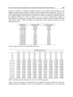
toward the GHz frequency regime with more than 10 million transistors on a die. Table 10.1 includes
some statistics of today’s leading microprocessors*:
Tanay Karnik
Intel Corporation
TABLE 10.1 Microprocessor Statistics
* The reader may refer to Refs. 3 through 10 for further details about these processors.
0–8493–1737–1/03/$0.00+$ 1.50
© 2003 by CRC Press LLC
10-2 Memory, Microprocessor, and ASIC
In order to understand the magnitude of the problem of laying out a high-performance
microprocessor, refer to the sample chip micrographs in Fig. 10.1. Various architectural modules, such as
functional blocks, datapath blocks, memories, memory management units, etc., are physically separated
on the die. There are many layout challenges apparent in this figure. The floorplanning of various
blocks on the chip to minimize chip-level global routing is done before the layout of the individual
blocks is available. The floorplanning has to fit the blocks together to minimize chip area and satisfy the
global timing constraints. The floorplanning problem is explained in Section 10.4.1 (Floorplanning). As
there are millions of devices on the die, routing power and ground signals to each gate involves careful
planning. The power routing problem is described in Section 10.4.2 (Clock Planning). The microprocessor
is designed for a particular frequency target. There are three key steps to high performance. The first
step involves designing a high-performance circuit family, the second one involves design of fast storage
elements, and the third is to construct a clock distribution scheme with minimum skew. Many elements
need to be clocked to achieve synchronization at the target frequency. Routing the global clock signal
exactly from an initial generator point to all of these elements within the given delay and skew budgets
is a hard task. Section 10.4.3 (Power Planning) includes the description of clock planning and routing
problems. There are various signal buses routed inside the chip running among chip I/Os and blocks.
A 64-bit datapath bus is a common need in today’s high-performance architectures, but routing that
wide a bus in the presence of various other critical signals is very demanding, as explained in Section
10.4.4 (Bus Routing).
The problems identified by looking at the chip micrographs are just a glimpse of a laborious layout
process. Before any task related to layout begins, the manufacturing techniques need to be stabilized
and the requirements have to be modeled as simple design rules to be strictly obeyed during the entire
design process. The manufacturing constraints are caused by the underlying process technology (Section
10.3.2, Technology Process) or packaging (Section 10.3.1, Packaging).
Another set of decisions to be taken before the layout process involves the circuit style(s) to be used
during the microprocessor design. Examples of such styles include full custom, semi-custom, and
automatic layout. They are described in Section 10.2. The circuit styles represent circuit layout styles,
but there is an orthogonal issue to them, namely, circuit family style. The examples of circuit families
include static CMOS, domino, differential, cascode, etc. The circuit family styles are carefully studied
for the underlying manufacturing process technology and ready-to-use cell libraries are developed to
be used during the block layout. The library generation is illustrated in Section 10.4.5.
FIGURE 10.1 Chip micrographs: (a) Compaq Alpha 21264; (b) HP PA-8000.
10-3Microprocessor Layout Method
Major layout effort is required for the layout of functional blocks. The layout of individual blocks is
usually done by parallel teams. The complex problem size prompts partitioning inside the block and
reusability across blocks. Cell libraries as well as shared mega-cells help expedite the process. Well-
established methodologies exist in various microprocessor design companies. Block-level layout is
usually done hierarchically. The steps for block-level layout involve partitioning, placement, routing, and
compaction. They are detailed in Section 10.4.6.
10.1.1 CAD Perspective
The complexity of microprocessor design is growing, but there is no proportional growth in design
team sizes. Historically, many tasks during the microprocessor layout were carefully hand-crafted. The
reasons were twofold. The size of the problem was much smaller than what we face today. The second
reason was that computer-aided design (CAD) was not mature. Many CAD vendors today are offering
fast and accurate tools to automatically perform various tasks such as floorplanning, noise analysis,
timing analysis, placement, and routing. This computerization has enabled large circuit design and fast
turn-around times. References to various CAD tools with their capabilities have been added through-
out this chapter.
CAD tools do not solve all of the problems during the microprocessor layout process. The regular
blocks, like datapath, still need to be laid out manually with careful management of timing budgets.
Designers cannot just throw the netlist over the wall to CAD to somehow generate a physical design.
Manual effort and tools have to work interactively. Budgeting, constraints, connectivity, and interconnect
parasitics should be shared across all levels and styles. Tools from different vendors are not easily
interoperable due to a lack of standardization. The layout process may have proprietary methodology
or technology parameters that are not available to the vendors. Many microprocessor manufacturers
have their own internal CAD teams to integrate the outside tools into the flow or develop specific
point tools internally. This chapter attempts to explain the advantages as well as shortcomings of CAD
for physical layout.
Invaluable information about physical design automation and related algorithms is provided in Refs.
11 and 12. These two textbooks cover a wide range of problems and solutions from the CAD perspective.
They also include detailed analyses of various CAD algorithms. The reader is encouraged to refer to
Refs. 13 to 15 for a deeper understanding of digital design and layout.
10.1.2 Internet Resources
The Internet is bringing the world together with information exchange. Physical design of micropro-
cessors is a widely discussed topic on the Internet. The following Web sites are a good resource for
advanced learning of this field.
The key conference for physical design is the International Symposium on Physical Design (ISPD),
held annually in April. The most prominent conference in the electronic design automation (EDA)
community is the ACM/IEEE Design Automation Conference (DAC), (www.dac.com). The conference
features an exhibit program consisting of the latest design tools from leading companies in design
automation. Other related conferences are the International Conference on Computer Aided Design
(ICCAD) (www.iccad.com), IEEE International Symposium on Circuits and Systems (ISCAS)
(www.iscas.nps.navy.mil), International Conference on Computer Design (ICCD), IEEE Midwest
Symposium on Circuits and Systems (MSCAS), IEEE Great Lakes Symposium on VLSI (GLSVLS)
(www.eecs.umich.edu/glsvlsi), European Design Automation Conference (EDAC), International
Conference on VLSI Design (vcapp.csee.usf.edu/vlsi99/), and Microprocessor Forum. Several journals
dedicated to the field of VLSI design automation include broad coverage of all topics in physical
design. They are IEEE Transactions on CAD of Circuits and Systems (akebono.stanford.edu/users/nanni/
tcad), Integration, IEEE Transactions on Circuits and Systems, IEEE Transactions on VLSI Systems, and the
10-4 Memory, Microprocessor, and ASIC
Journal of Circuits, Systems and Computers. Many other journals occasionally publish articles of interest to
physical design. These journals include Algorithmica, Networks, SIAM Journal of Discrete and Applied Mathematics,
and IEEE Transactions on Computers.
An important role of the Internet is through the forum of newsgroups. comp.lsi.cad is a newsgroup
dedicated to CAD issues, while specialized groups such as comp.lsi.testing and comp.cad.synthesis
discuss testing and synthesis topics. The reader is encouraged to search the Internet for the latest topics.
EE Times (www.eet.com) and Integrated System Design (www.isdmag.com) magazines provide the latest
information about physical design (PD) and both are online publications. Finally, the latest challenges
in physical design are maintained at (www.cs.virginia.edu/pd_top10/). The current benchmark problems
for comparison of PD algorithms are available at www.cbl.ncsu.edu/www/.
We describe various problems involved throughout the microprocessor layout process in Section 10.2.
10.2 Layout Problem Description
The design flow of a microprocessor is shown in Fig. 10.2. The architectural designers produce a high-
level specification of the design, which is translated into a behavioral specification using function
design, structural specification using logic design, and a netlist representation using circuit design. In
this chapter, we discuss the microprocessor layout method called physical design. It converts a netlist into
a mask layout consisting of physical polygons, which is later fabricated on silicon. The boxes on the
right side of Fig. 10.2 depict the need for verification during all stages of the design. Due to high
frequencies and shrinking die sizes, estimation of eventual physical data is required at all stages before
physical design during the microprocessor design process. The estimation may not be absolutely nec-
essary for other types of designs.
Let us consider the physical design process. Given a netlist specification of a circuit to be designed, a
layout system generates the physical design either manually or automatically and verifies that the design
conforms to the original specification. Figure 10.3 illustrates the microprocessor physical design flow.
Various specifications and constraints have to be handled during microprocessor layout. Global
specs involve the target frequency, density, die size, power, etc. Process specs will be discussed in Section
10.3. The chip planner is the main component of this process. It partitions the chip into blocks, assigns
blocks for either full custom (manual) layout or CAD (automatic) layout and assembles the chip after
block-level layout is finished. It may also iterate this process for better results. Full custom and CAD
layout differ in the approach to handle critical nets. In the custom layout, critical nets are routed as a
first step of block layout. In the CAD approach, the critical net requirements are translated into a set
FIGURE 10.2 Microprocessor design flow.
10-5Microprocessor Layout Method
of constraints to be satisfied by placement and routing tools. The placement and global routing have to
work in an iterative fashion to produce a dense layout. The double-sided arrow in the CAD box
represents this iteration. In both layout styles, iterations are required for block layout to completely
satisfy all the specs. Some microprocessor teams employ a semi-custom approach which takes advantage
of careful hand-crafting and power savings on the full custom side, and the efficiency and scalability of
the CAD side.
10.2.1 Global Issues
The problems specific to individual stages of physical design are discussed in the following sections.
This section attempts to explain the problems that affect the whole design process. Some of them may
be applicable to the pre-layout design stages and post-layout verification.
Planning
There has to be a global flow to the layout process. The flow requires consistency across all levels and
support for incremental re-design. A decision at one level affects almost all the other levels. The chip
planning and assembly are the most crucial tasks in the microprocessor layout process. The chip is
partitioned into blocks. Each block is allotted some area for layout. The allotment is based on estima-
tion based on past experience. When the blocks are actually laid out, they may not fit in the allotted
area. The full microprocessor layout process is long. One cannot wait until the last moment to assemble
the blocks inside the chip. The planning and assembly team has to continuously update the flow, chip
plans, and block interfaces to conform to the changing block data.
Estimation
New product generations rely on technology advances and providing the designer with a means of
evaluating technology choices early in the product design.
16
Today’s fine-line geometries jeopardize
timing. Massive circuit density, coupled with high clock rates, is making routed interconnects hardest
to gauge early in the design process. A solid estimation tool or methodology is needed to handle
today’s complex microprocessor designs. Due to the uncertain effects of interconnect routing, the wall
between logical and physical design is beginning to fall.
17
In the past, many microprocessor layout
teams resorted to post-layout updates to resolve interconnect problems, This may cause major re-
design and another round of verification, and is therefore not acceptable. We cannot separate logical
design and physical design engineers. Chip planners have to minimize the problems that interconnect
FIGURE 10.3 Microprocessor physical design flow.
10-6 Memory, Microprocessor, and ASIC
effects may cause. Early estimation of placement, signal integrity, and power analysis information is
required at the floorplanning stage even before the structural netlist is available.
Changing Specifications
Microprocessor design is a long process. It is driven by market conditions, which may change during
the course of the design. So, architectural specs may be updated during the design. During physical
design, the decisions taken during the early stages of the design may prove to be wrong. Some blocks
may have added functionalities or new circuit families, which may need more area. The global abstract
available to block-level designers may continuously change, depending on sibling blocks and global
specs. Hence, the layout process has to be very flexible. Flexibility may be realized at the expense of
performance, density, or area—but it is well worth it.
Die Shrinks and Compactions
The easiest way to achieve better performance is process shrinks. Optical shrinks are used to convert
a die from one process to a finer process. Some more engineering is required to make the micropro-
cessor work for the new process. A reduction in feature size from 0.50 µm to 0.35 µm results in an
increase of approximately 60% more devices on a similarly sized die.
3
Layouts designed for a manufac-
turing process should be scalable to finer geometries. The decisions taken during layout should not
prohibit further feature shrinks.
Scalability
CAD algorithms implemented in automatic layout tools must be applicable to large sizes. The same
tools must be useful across generations of microprocessor. Training the designers on an entirely new set
of CAD tools for every generation is impractical. The data representation inside the tools should be
symbolic so that the process numbers can be updated without a major change in tools.
10.2.2 Explanation of Terms
There are many terms related to microprocessor layout used in the following sections. The definitions
and explanation of those terms are provided in this section.
Capacitance: A time-varying voltage across two parallel metal segments exhibits capacitance. The
voltage (v) and current (i) relation across a capacitor (C) is:
Closely spaced unconnected metal wires in layout can have significant cross-capacitance.
Capacitance is very significant at 0.5-µm process and beyond.
18
Inductance: A time-varying current in a wire loop exhibits inductance. If the current through a power
grid or large signal buses changes rapidly, this can have inductive effects on adjacent metal wires.
The voltage (v) and current (i) relation across an inductor (L) is:
Inductance is not a local phenomenon like capacitance.
Parasitics: The shrinking technology and increasing frequencies are causing analog physical behavior
in digital microprocessors.
19
The electrical parameters associated with final physical routes are
called interconnect parasitics. The parasitic effects in the metal routes on the final silicon need to
be estimated in the early phases of the design.
10-7Microprocessor Layout Method
Design rules: The process specification is captured in an easy-to-use set of rules called design rules.
Spacing: If there is enough spacing between metal wires, they do not exhibit cross-capacitance.
Minimum metal spacing is a part of the design rules.
Shielding: The power signal is routed on a wide metal line and does not have time-varying properties.
In order to reduce external effects like cross-capacitance on a critical metal wire, it is routed
between or next to a power wire. This technique is called shielding.
Electromigration: Also known as metal migration, it results from a conductor carrying too much
current. The result is a change in conductor dimensions, causing high resistive spots and eventual
failure. Aluminum is the most commonly used metal in microprocessors. Its current density
(current per width) threshold for electromigration is:
10.3 Manufacturing
Manufacturing involves taking the drawn physical layout and fabricating it on silicon. A detailed
description of fabrication processes is beyond the scope of this book. Elaborate descriptions of the
fabrication process can be found in Refs. 11 and 13. The reader may be curious as to why manufacturing
has to be discussed before the layout process. The reality is that all of the stages in the layout flow need
a clear specification of the manufacturing technology. So, the packaging specs and design rules must be
ready before the physical design starts.
In this section, we present a brief overview of chip packaging and the technology process. The
reader is advised to understand the assessment of manufacturing decisions (see Ref. 16). There is a
delicate balancing of the system requirements and the implementation technology. New product
generation relies on technology advances and providing the designer with a means of evaluating
technology choices early in the product design.
10.3.1 Packaging
ICs are packaged into ceramic or plastic carriers usually in the form of a pin grid array (PGA) in which
pins are organized in several concentric rectangular rows. These days, PGAs have been replaced by
surface-mount assemblies such as ball grid arrays (BGAs) in which an array of solder balls connects the
package to the board. There is definitely a performance loss due to the delays inside the package. In
many microprocessors, naked dies are directly attached to the boards. There are two major methods of
attaching naked dies. In wire bonding, I/O pads on the edge of the die are routed to the board. The
active side of the die faces away from the board and the I/Os of the die lie on the periphery
(peripheral I/Os). The other die attachment, control collapsed chip connection (C4) is a direct con-
nection of die I/Os and the board. The I/O pins are distributed over the die and a solder ball is placed
over each I/O pad (areal I/Os). The die is flipped and attached to the board. The technology is called
C4 flip-chip. Figure 10.4 provides an abstract view of the two styles.
There is a discussion about practical issues related to packaging available in Ref. 20. According to
the Semiconductor Industry Association’s (SIA) roadmap, there should be 600 I/Os per package in
2507 rows, 7 µm package lines/space, 37.5 µm via size, and 37.5 µm landing pad size by the year 1999.
The SIA roadmap lists the following parameters that affect routing density for the design of packaging
parameters:
• Number of I/Os: This is a function of die size and planned die shrinks. The off-chip connectivity
requires more pins.
• Number of rows: The number of rows of terminals inside the package.
• Array shape: Pitch of the array, style of the array (i.e., full array, open at center, only peripheral).
10-8 Memory, Microprocessor, and ASIC
• Power delivery: If the power and ground pins are located in the middle, the distribution can be
made with fewer routing resources and more open area is available for signals, but then the
power cannot be used for shielding the critical signals.
• Cost of package: This includes the material, processing cost, and yield considerations. The current trend
in packaging indicates a package with 1500 I/O on the horizon and there are plans for 2000 I/Os.
There is a gradual trend toward the increased use of areal I/Os. In the peripheral method, the I/Os on
the perimeter are fanned out until the routing metal pitch is large enough for the chip package and
board to handle it. There may be high inductance in the wire bonding. Inductance causes current time
delay at switching, slow rise time, and ground bounce in which the ground plane moves away from 0
V, noise, and timing problems. These effects have to be handled during a careful layout of various
critical signals. Silicon array attachments and plastic array packages are required for high I/O densities
and power distribution. In microprocessors, the packaging technology has to be improvised because of
the growth in bus widths, additional metal layers, less current capacity per wire, more power to be
distributed over the die, and the growing number of data and control lines due to bus widths. The
number of I/Os has exceeded the wire bonding capacity. Additionally, there is a limit to how much a
die can be shrunk in the wire bonding method. High operating frequencies, low supply voltage, and
high current requirements manifest themselves into a difficult power distribution across the whole die.
There are assembly issues with fine pitches for wire bonds. Hence, the microprocessor manufacturers
are employing C4 flip-chip technologies. Areal packages reduce the routing inside the die but need
more routing on the board.
The effect of area packaging is evident in today’s CAD tools.
21
The floorplanner has to plan for areal
pads and placement of I/O buffers. Area interconnect facilitates high I/O counts, shorter interconnect
rates, smaller power rails, and better thermal conductivity. There is a need for an automatic area pad
planner to optimize thousands of tightly spaced pads. A separate area pad router is also desired. The
possible locations for I/O buffers should be communicated top-down to the placement tool and the
placement info should be fed back to the I/O pad router. After the block level layout is complete and the
chip is assembled, the area pad router should connect the power pads to inner block-level power rails.
Let us discuss some industry microprocessor packaging specs. The packaging of DEC/Compaq’s
Alpha 21264 has 587 pins.
4
This microprocessor contains distributed on-chip decoupling capacitors
(decap) as well as a 1-µm package decap. There are 144-bit (128-bit data, 16-bit ECC) secondary cache
data interfaces and 72-bit system data interfaces. Cache and system data pins are interleaved for efficient
multiplexing. The vias have to arrayed orthogonal to the current flow. HP’s PA-8000 has a flip-chip
package, which enables low resistance, less inductance, and larger off-chip cache support. There are
704 I/O signals and 1200 power and ground bumps in the 1085-pin package. Each package pin fans
out to multiple bumps.
6
PowerPC
™
has a 255-pin CBGA with C4 technology.
7
431 C4’s are distributed
FIGURE 10.4 Die attachment styles.
10-9Microprocessor Layout Method
around the periphery. There are 104 VDD and GND internal C4’s. The C4 placement is done for
optimal L2 cache interface.
There is a debate about moving from high-cost ceramic to low-cost plastic packaging. Ceramic ball
grid arrays suffer from 50% propagation speed degradation due to high dielectric constant (10). There
is a trend to move toward plastic. However, ceramic is advantageous in thermal conductivity and it
supports high I/O flip-chip packaging.
10.3.2 Technology Process
The whole microprocessor layout is driven by the underlying technology process. The process engineers
decide the materials for dielectric, doping, isolation, metal, via, etc. and design the physical properties
of various lithographic layers. There has to be close cooperation between layout designers and process
engineers. Early process information and timely updates of technology parameters are provided to the
design teams, and a feedback about the effect of parameters on layout is provided to the process teams.
Major process features are managed throughout the design process. This way, a design can be better
optimized for process, and future scaling issues can be uncovered.
The main process features that affect a layout engineer are metal width, pitch and spacing specs, via
specs, and I/O locations. Figure 10.5(a) shows a sample multi-layer routing inside a chip. Whenever two
metal rails on adjacent layers have to be connected, a via needs to be dropped between them. Figure
10.5(b) illustrates how a via is placed. The via specs include the type of a via (stacked, staggered),
coverage of via (landed, unlanded, point, bar, arrayed), bottom layer enclosure, top layer enclosure, and
the via width. In today’s microprocessors, there is a need for metal planarization. Some manufacturers
are actually adding planarization metal layers between the usual metal layers for fabrication as well as
shielding. Aluminum was the most common metal for fabrication. IBM has been successful in getting
copper to work instead of aluminum. The results show a 30% decrease in interconnect delay.
The process designers perform what-if analyses and design sensitivity studies of all of the process
parameters on the basis of early description of the chip with major datapath and bus modeling, net
constraints, topology, routing, and coupled noise inside the package. The circuit speed is inversely
proportional to the physical scale factor. Aggressive process scaling makes manufacturing difficult. On
the other hand, slack in the parameters may cause the die size to increase. We have listed some of the
process numbers in today’s leading microprocessors in this section. The feature sizes are getting very
small and many unknown physical effects have started showing up.
22
The processes are so complicated
to correctly obey during the design, an abstraction called design rules is generated for the layout
engineers. Design rules are constraints imposed on the geometry or topology of layouts and are derived
from basic physics of circuit operation such as electromigration, current carrying capacity, junction
breakdown, or punch-through, and limits on fabrication such as minimum widths, spacing requirements,
FIGURE 10.5 A view of (a) multi-layer routing and (b) a simple via.
10-10 Memory, Microprocessor, and ASIC
misalignments during processing, and planarization. The rules reflect a compromise between fully
exploiting the fabrication process and producing a robust design on target.
5
As feature sizes are decreasing, optical lithography will need to be replaced with deep-UV, x-ray, or
electron beam techniques for features sizes below 0.15 µm.20 It was feared that quantum effects would
start showing up below 0.1 µm. However, IBM has successfully fabricated a 0.08-µm chip in the
laboratory without seeing quantum effects. Another physical limit may be the thickness of the gate
oxide. The thickness has dropped to a few atoms. It is soon going to hit a fundamental quantum limit.
Alpha 21264 has 0.35-µm feature size, 0.25-µm effective channel length, and 6-nm gate oxide. It has
four metal layers with two reference planes. All metal layers are AlCu. Their width/pitches are 0.62/
1.225, 0.62/1.225, 1.53/2.8, and 1.53/2.8 µm, respectively.
4
Two thick aluminum planes are added to the
process in order to avoid cycle-to-cycle current variations. There is a ground reference plane between
metal2 and metal3, and a VDD reference plane above metal4. Nearly the entire die is available for power
distribution due to the reference planes. The planes also avoid inductive and capacitive coupling.
8
PowerPC
™
has 0.3-µm feature size, 0.18-µm effective channel length, 5-nm gate oxide thickness, and
a five-layer process with tungsten local interconnect and tungsten vias.
7
The metal widths/pitches are
0.56/0.98, 0.63/1.26, 0.63/1.26, 0.63/1.26, and 1.89/3.78 µm, respectively.
HP-8000 has 0.5-µm feature size and 0.29-µm effective channel length.
6
There is a heavy investment
in the process design for future scaling of interconnect and devices. There are five metal layers, the
bottom two for local fine routing, metal3 and metal4 for global low resistive routing, and metal5
reserved for power and clock. The author could not find published detailed metal specs for this
microprocessor.
Intel Pentium II is fabricated with a 0.25-µm CMOS four-layer process.
23
The metal width/pitches
are 0.40/1.44,.64/1.36,.64/1.44, and 1.04/2.28 µm, respectively. The two lower metal layers are usually
used in block-level layout, metal3 is primarily used for global routing, and metal4 is used for top-level
chip power routing.
10.4 Chip Planning
As explained in Section 10.2, chip planning is the master step during the layout of a microprocessor.
During the early stages of design, the planning team has to assign area, routing, and timing budgets to
individual blocks on the basis of some estimation methods. Top-down constraints are imposed on the
individual blocks. During the block layout, continuous bottom-up feedback to the planner is neces-
sary in order to validate or update the imposed constraints and budgets. Once all the blocks have been
laid out and their accurate physical information is available, the chip planning team has to assemble the
full chip layout subject to the architectural and process specs.
Chip planning involves partitioning the microprocessor into blocks. The finite state machines are
considered random control logic and partitioned into automatically synthesizable blocks. Regular
structures like arrays, memories, and datapath require careful signal routing and pitch matching. They
have to be partitioned into modular and regular blocks that can be laid out using full-custom or semi-
custom techniques.
IBM adopted a two-level hierarchical approach for the G4 processor.
24
They identified groups of
10,000 to 20,000 non-array transistors as macros. Macros were individually laid out by parallel teams.
The macro layouts were simplified and abstracted for floorplanning, place and route, and global extraction.
The shapes of individual blocks varied during the design process. The chip planner performed the
layouts for global interconnects and physical design of the entire chip. The global environment was
abstracted down to the block level. A representation of global wires was added overlaying a block. That
included global timing at block interfaces, arrival times with phase tags at primary inputs (PI), required
times with phase tags at primary outputs (PO), PI resistances, and PO capacitances. Capacitive loading
at the outputs was based on preliminary floorplan analysis. Each block was allowed sufficient wiring
and cell area. The control logic was synthesized with a high-performance standard cell library; datapaths
10-11Microprocessor Layout Method
were designed with semi-custom macros. Caches, memory management unit (MMU) arrays, branch
unit arrays, phase-locked loop (PLL), and delay-locked loop (DLL) were all full-custom layouts.
7
There
were three distinct physical design styles optimizing for different goals; namely, full custom for high
performance and density, structured custom for datapath, and fully automated for control logic. The
floorplan was flexible throughout the methodology. There are 44% memory arrays, 21% datapath, 15%
control, 11% I/O, and 9% miscellaneous blocks on the die. Final layout was completely hierarchical
with no limits on the levels of hierarchy involved inside a block. The block layouts had to conform to
a top abstracted global shadow of interconnects and blockages. The layout engineers performed post-
placement re-tuning and post-placement optimization for clock and scan chains.
For the 1-GHz integer PowerPC
™
microprocessor, the planning team at IBM enforced strict
partitioning on latch boundaries for global timing closure.
5
The planning team constructed a layout
description view of the mega-cells containing physical shape data of the pads, power buses, clock
spine, and global interconnects. At the block level, pin locations, capacitance, and blockages were
available. The layouts were created by hand due to the very high-performance requirements of the
chip.
We describe the major steps during the planing stages, namely, floorplanning, power planning, clock
planning, and bus routing. These steps are absolutely essential during microprocessor design. Due to
the complicated constraints, continuous intelligent updates, and top-down/bottom-up communication,
manual intervention is required.
10.4.1 Floorplanning
Floorplannig is the task of placing different blocks in the
chip so as to fit them in the minimum possible area with
minimum empty space. It must fill the chip as close to the
brim as possible. Figure 10.6 shows an example of
floorplanning. The blocks on the left-hand side are fitted
inside the chip on the right. The reader can see that there
is very little empty space on the chip. The blocks may be
flexible and their orientation not fixed. Due to the
dominance of interconnect in the overall delay on the
chip, today’s floorplanning techniques also try to minimize
global connectivity and critical net lengths.
There are many CAD tools available for floorplanning from the EDA vendors. The survey of all
such tools is available.
25
The tools are attempting to bridge the gap between synthesis and layout. All of
the automatic tools are independent of IC design style. There are two types of floorplanners. Functional
floorplanners operate at the RTL level for timing management and constraints generation. The goal of
physical floorplanners is to minimize die size, maximize routability, and optimize pin locations. Some
physical floorplanners perform placement inside floorplanning. As explained in the routing section,
when channel routing is used, the die size is unpredictable. The floorplanners cannot estimate routing
accurately. Hence, channel allocation on the die is very difficult. Table 10.2 summarizes the CAD tools
available for floorplanning.
10.4.2 Clock Planning
Clock is a global signal and clock lines have to be very long. Many elements in high-frequency
microprocessors are continuously being clocked. Different blocks on the same die may operate at
different frequencies. Multiple clocks are generated internally and there is a need for global synchro-
nization. Clock methodology has to be carefully planned and the individual clocks have to be gener-
ated and routed from the chip’s main phase-locked loop (PLL) to the individual sink elements. The
FIGURE 10.6 An example of floorplanning.
10-12 Memory, Microprocessor, and ASIC
delays and skews (defined later) have to exactly match at every sink point. There are two major types
of clock networks, namely, trees and grids. Figure 10.7 illustrates a modified H-tree with clock buffers.
Figure 10.8 shows a clock grid used in Alpha processors. Most of the power consumption inside today’s
high-frequency processors is in their clock networks. In order to reduce the chip power, there are
architectural modifications to shut off some part of the chip. This is achieved by clock gating. The
clock gator routing has become an integral part of clock routing.
Let us explain some of the terms used in clock design. Clock skew is the temporal variation of the
same clock edge arriving at various locations on the die. Clock jitter is the temporal variation of
FIGURE 10.7 A sample global clock buffered H-tree.
FIGURE 10.8 A sample clock grid.
TABLE 10.2 CAD Tools Available for Floorplanning
10-13Microprocessor Layout Method
consecutive clock edges arriving at the same location. Clock delay is the delay from the source PLL to
the sink element. Both skew and jitter have a direct relation to clock delay. Globally synchronous
behavior dictates minimum skew, minimum jitter, and equal delay.
Clock grids, being perfectly symmetric, achieve very low skews, but they need high routing resources
and stacked vias, and cause signal reflections. The wire loading on driving buffers feeding to the grid
is also high. This requires large buffer arrays that occupy significant device area. Electrical analysis of
grids is more difficult than trees. Buffered trees are preferred in high-performance microprocessors
because they achieve acceptable skews and delays with low routing resource usage.
Ideally, the skew should be 0. However, there are many unknowns due to processing and randomness
in manufacturing. Instead of matching the clock receivers exactly, a skew budget is assigned. In high-
performance microprocessor designs, there is usually a global clock routing scheme (GCLK) that
spawns into multiple matched clock points in various regions on the chip. Inside the region, careful
clock routing is performed to match the clock delay within assigned skew budgets.
Alpha 21264 has a modified H-tree. On-chip PLL dissipates power continuously; 40% of the chip
power dissipation was measured to be in the clocking network. Reduction of clock power was a
primary concern to reduce overall chip power.
26
There is a GCLK network that distributes clock to
local clock buffers. GCLK is shielded with VCC or VSS throughout the die.
4
GCLK skew is 70 ps, with
50% duty cycle and uniform edge rate.
8
The clock routing is done on metal3 and metal4. In earlier
Alpha designs, a clock grid was used for effective skew minimization. The grid consumed most of the
metal3 and metal4 routing resources. In 21264, there is a savings of 10 W power over previous grid
techniques. Also, significantly less metal3 and metal4 is used for clock routing. This proved that a less
aggressive skew target can be achieved with a sparser grid and smaller drivers. The new technique also
helped power and ground networks by spreading out the large clock drivers across the die.
HP-8000 also has a modified H-tree for clock routing.
6,18
External clock is delivered to the chip PLL
through a C4 bump. The microprocessor has a three-level clock network. There is a modified H-tree that
routes GCLK from PLL to 12 secondary buffers strategically placed at various critical locations in various
regions on the chip. The output of the receiver is routed to matched wire lengths to a second level of
clock buffers. The third level involves 7000 clock gators that gate the clock routing from the buffers to
local clock receivers. There are many flavors of gated clocks on the chip. There is a 170-ps skew across the
die. Due to a large die, PA8000 buffers were designed to minimize process variations.
In PowerPC
™
, a PLL is used for internal GCLK and a DLL is used for external SRAM L2 interface.
7
There is a semi-balanced H-tree network from PLL to local regenerators. Semi-balanced means the
design was adjusted for variable skew up to 55 ps from main PLL to H-tree sinks. There are three
variations of masking 486 local clock regenerators. The overall skew across the die was 300 ps.
Many CAD vendors have attempted to provide clock routing technologies. The microprocessor
community is very paranoid about clock and clocking power. The designers prefer hand-crafting the
whole clock network.
10.4.3 Power Planning
Every gate on the die needs the power and ground signals. Power arrives at many chip-level input pins
or C4 bumps and is directly connected to the topmost metal layer. Routing power and ground from
the topmost layer to each and every gate on the die without consuming too many routing resources,
not causing voltage drops in the power network, and using effective shielding techniques constitutes
the power planning problem. A high-performance power distribution scheme must allow for all cir-
cuits on the die to receive a constant power reference. Variation in the reference will cause noise
problems, subthreshold conduction, latch-up, and variable voltage swings.
The switching speed of CMOS circuits in the first order is inversely proportional to the drain-to-
source current of the transistor (I
ds
), in the linear region:
10-14 Memory, Microprocessor, and ASIC
where C is the loading capacitance, V is the output voltage, and t is the switching delay. I
ds
, in turn,depends
on the IR-drop (V
drop
) as:
where V
gs
is the gate to source voltage and V
t
is the threshold voltage of the MOS transistor. Therefore,
achieving the highest switching speed requires distributing the power network from the pads at the
periphery of the die or C4 bumps to the sources of the transistors with minimal IR drop due to
routing. The problem of reducing V
drop
is modeled in terms of minimum allowable voltage at the source
and the difference between Vdd and Vss acceptable at the sinks. All physical stages from pads to pins
have to be considered. Some losses, like tolerance of the power supply, the tester guardband, and power
drop in the package, are out of the designer’s control. The remaining IR-drop budget is divided among
global and local power meshes.
The designers at Motorola have provided a nice overview of power routing in Ref. 27. Their design
of PowerPC
™
power grid continued across all design stages. A robust grid design was required to
handle the possible switching and large current flow into the power and ground networks. Voltage
drops in power grid cause noise, degrading performance, high average current densities, and undesirable
wearing of metal. The problem was to design a grid achieving perfect voltage regulation at all demand
points on the chip, irrespective of switching activities and using minimum metal layers. The PowerPC™
processor family has a hierarchy of five or six metal layers for power distribution. Structure, size, and
layout of the power grid had to be done early in the design phase in the presence of many unknowns
and insufficient data. The variability continued until the end of design cycle. All commercial tools
depend on post-layout power grid analysis after the physical data is available. One cannot change the
power plan at that stage because too much is at stake toward the end. Hence, Motorola designers used
power analysis tools at every stage. They generated applicable constant models for every stage. There are
millions of demand points in a typical microprocessor. One cannot simulate all non-linear devices with
a non-ideal power grid. Therefore, the approach was as follows. They simulated non-linear devices with
fixed power, converted all devices to current sources, and then analyzed the power grid. There was still
a large linear system to handle. So, a hierarchical approach was used. Before the floorplaning stage, the
locations of clean VCC/GND pads and power grid widths/pitches were decided on the basis of
design rules and via styles (point or bar vias). After the floorplan was fixed, all blocks were given block
power service terminals. Wires that connect global power to block power were also modeled in the
service terminals. Power was routed inside the blocks and PowerMill simulations were used for validation.
Alpha 21264 operates at a high frequency and has a large die as listed in Table 10.1. The large die and
high frequency lead to high power supply currents. This has a serious effect on power, clock, and
ground networks.
3,4
Power dissipation was the sole factor limiting chip complexity and size; 198 out of
587 chip-level pins are VDD and VSS pins. Supply current has doubled during every generation of
Alpha microprocessor. Hence, a very complex power distribution was required. In order to meet very
large cycle-to-cycle current variations, two thick low-resistance aluminum planes were added to the
process.
8
One plane was placed between metal2 and metal3 connected to VSS, and the other above the
topmost metal4 connected to VDD. Nearly the entire die area was available for power distribution. This
helped in inductive and capacitive decoupling, reduced on-chip crosstalk, and presented excellent
current returns paths for analysis and minimized inductive noise.
UltraSPARC-I
™
has 288 power and ground pins out of 520.
9
The methodology involved an early
identification of excessive voltage drop points and seamless integration of power distribution and CAD
tools. Correct-by-construction power grid design was done throughout the design cycle. The power
networks were designed for cell libraries and functional blocks. They were reliability-driven designs
before mask generation. This enabled efficient distribution of the Vdd and Vss networks on a large die.
Minimization of area overhead, as well as IR drop for power distribution, was considered throughout the
design cycle. Parts of power distribution network are incorporated into the standard cell library layouts.
CAD tools were used for the composition of standard cell and datapath with correct-by-construction
10-15Microprocessor Layout Method
power interconnections. The methodology was designed to be scalable to future generations. Estimation
and budgeting of IR-drops was done across the chip. Metal4 was the only over-the-block routing layer.
It was used for routing power from peripheral I/O pads to individual functional units. It was the primary
means of distributing power. The power distribution should not constrain the floorplan. Hence, two
meshes were laid out: a top-down global mesh and an in-cell local mesh. This enabled block movement
during placement because they have only local mesh. As long as the local power mesh crosses the global
mesh, the power can be distributed inside the block. Metal3 local power routes have to be orthogonal to
global metal4 power. The direction of metal1 and metal2 do not matter. The global chip is divided into
two parts. In part 1, metal3 was vertical and metal4 was horizontal. The opposite directions were selected
for the second part. A block could be moved half the die distance because of two types of regions for
power on the chip. The power grid on three metal layers with interconnections, number of vias, and via
types was simulated using HSPICE to determine the widths, spacings, and number of vias of the power
grid. Vias had to be arrayed orthogonal to the current flow. There was a 90-mV IR-drop from M3-M4 via
to the source of a cell. Additional problems existed because the metal2 width is fixed in UltraSPARC™.
Up to a certain drive strength, the metal2 power rail was 2.5 µm. Beyond that, additional rail of 1 µm was
added. The locations of clock receivers changed throughout the design process. They had to be shifted
to align power.
10.4.4 Bus Routing
The author considers bus routing a critical problem and it needs the same attention as power or clock
routing. The problem arises due to today’s superscalar, large bit-width microprocessor architectures.
The chip planners design the clock and power plans and floorplan the chip very efficiently to mini-
mize empty space on the die, but leave limited routing resources on the top layers to route busses.
There is a simple analogy to understand this problem. Whenever a city is being planned, the roads are
constructed before the individual buildings. In microprocessor layout, buses must be planned before
the blocks are laid out.
A bus, by nature, is bi-directional and must have matching characteristics at all data bits. There
should be a matching RC delay viewed from both ends. It connects a wide datapath to another. If it
is routed straight from one datapath block to another, then the characteristics match; but it is not
always feasible on the die to achieve straight routes. Whenever there is a directional change, via delay
comes into picture. The delays due to via and uneven lengths for all the bit-lines in the bus cause a
mismatch across the bits of the bus. Figure 10.9 depicts a simple technique called bus interleaving,
employed in today’s microprocessors, to achieve matching lengths.
The problems do not end there. Bus interleaving may match the lengths across the bit-widths, but
it does not guarantee matching environment for all the bit-lines. Crosstalk due to adjacent layers or
buses may cause mismatch among the bit-lines. In differential circuits, very low voltage buses are routed
with long routing lengths. Alpha designers had to carefully route low swing buses in 21264 to minimize
all differential noise effects.
3
These types of buses need shielding to protect the low-voltage signals. If
all bits in a bus switch simultaneously, large current variations inject inductive noise into the neighboring
signal lines. Hence, other signals also need to be shielded from active buses.
FIGURE 10.9 Bus interleaving.
10-16 Memory, Microprocessor, and ASIC
10.4.5 Cell Libraries
A major step toward high performance is the availability of a fast ready-to-use circuit library. Due to
large and complex circuit sizes, transistor-level layout is formidable. All microprocessor teams design a
family of logic gates to perform certain logic operations. These gates become the bottom level units in
the netlist hierarchy. They serve as a level of abstraction higher than a basic transistor. Predefined logic
functions help in automatic synthesis. The gates may differ in their circuit family, logic functions, drive
strength, power consumption, internal layout, placement of cell interface ports, power rails, etc. The
number of different cells available in the design libraries can be as high as 2000. The libraries offer the
most common predefined building blocks of logic and low-level analog and I/O functions. Complex
designs require multiple libraries. The libraries enable fast time to market, aid synthesis in logic
minimization, and provide an efficient representation of logic in hardware description languages.
Block-level layout tools support cell-based layout. They need the cells to be of a certain height and
perform fast row-based layout. The block-level layout tools are very mature and fast. Many microprocessor
design teams design their libraries to be directly usable by block-level layout tools. There are many
CAD tools available for cell designs and cell-based block designs. The most common approach is to
develop a different library for each process and migrate the design to match the library. Process-specific
libraries lead to small die size with high performance. There are tools available on the market for
automatic process porting, but the portability across processes causes performance and area degradation.
Microprocessor manufacturers have their in-house libraries designed and optimized for proprietary
processes. The cell libraries have to be designed concurrently with the process design and they must
be ready before the block-level design begins. The libraries for datapath and control can differ in styles,
size, and routing resource utilization. As datapath is considered crucial to a microprocessor, datapath
libraries may not support porosity, but the control logic library has to provide porosity for neighboring
datapath cells to use some of its routing resources. Thus, datapath libraries are designed for higher
performance than control. In UltraSPARC-I
™
processor, the design team at Sun Microsystems used
separate standard cells for datapath and control.
9
In this section, we present various layout aspects of cell library design. The reader is requested to
refer to Refs. 13–15 for circuit aspects of libraries.
Circuit Family
The most common circuit family is CMOS. They are very popular because of the static nature. It is a
fully restored logic in which output either sets at Vdd or Vss. The rise and fall times are of the same
order. This family has almost zero static power dissipation. The main advantage in layout is its symmetric
nature, nice separation of n and p transistors, and ability to produce regular layouts. Figure 10.10 shows
a three-input CMOS NOR library cell.
The other popular circuit family in high-performance microprocessors is that of dynamic circuits.
The inputs feed into the n-stack and not the p-stack. There is a precharge p-transistor and a smaller
keeper p-transistor in the p-stack. So, the number of transistors in p-stack is exactly 2. The dynamic
circuits need careful analysis and verification, but allow wide OR structures, less fan-in and fan-out
capacitance. The switching point is determined by the nMos threshold and there is no crossover
current during output transition. As there is less loading on the inputs, this circuit family is very fast. As
one can see in Fig. 10.10, the area occupied by the p-stack is very large compared to the n-stack in
static CMOS. Domino logic families have a significant area advantage over static if the same static netlist
can be synthesized in monotonic domino gates. However, layout of domino gates is not trivial. Every
gate needs a clock routed to it. As the family does not support fully restoring logic, the domino gate
output needs to be shielded from external noise sources. Additional circuitry may be required to avoid
charge-sharing and noise problems.
Other circuit families include BiCMOS, in which bipolar transistors are used for high speed and
CMOS transistors are used for low-power, high-density gates; differential cascode voltage switch logic
10-17Microprocessor Layout Method
(DVSL), in which differential output logic uses positive feedback for speed-up; differential split-level
logic (DSL), in which load is used to reduce output voltage swing; and pass transistor logic (PTL), in
which complex logic such as muxing is easily supported.
Cell Layout Architecture
There are various issues involved in deciding how a cell should be laid out. Let us look at some of the
issues.
Cell height: If row-based block layout tools are going to be used, then the cells should be designed
to have standard heights. This approach also helps in placement during full-custom layout. Basi-
cally, constraining one dimension (height) enables better optimization for the other one (width).
However, snapping to a particular height may cause unnecessary waste of active transistor area for
cells with small drive strengths.
Diffusion orientation: Manufacturing may cause some variation in cell geometries. In order to
achieve consistent variations across all transistors inside a cell, process technology may dictate
fixed orientation of transistors.
Metal usage: Cells are part of a larger block. They should allow block-level over-the-cell routing.
Guidelines for strict metal usage must be followed while laying out cells. Some cell guidelines
may force single-metal usage inside the cell.
Power: Cells must adhere to the block-level power grid. They should either instantiate power pins
internally and include the power pins in the interface view, or should enable block-level power
routing by abutment. In UltraSPARC-I
™
, there was a clear separation of metal usage between
datapath and control standard cells. The power in control was distributed on horizontal metal1
with adjacent cells abutting the rails. Metal2 was only used to connect metal1 to metal3 power.
Metal2 power hook-up could have been longer for better power delivery, but it would consume
routing resources. The datapath library had vertical metal2 abutting for power and it was directly
connected to metal3 power grid.
9
FIGURE 10.10 A three-input CMOS NOR layout.
10-18 Memory, Microprocessor, and ASIC
Cell abstraction: Internal layout details of a cell are not required at the block level. Cells should be
abstracted to provide a simplified view of interface pins (ports), power pins, and metal obstructions.
Design guidelines may have requirements for coherent cell abstract views. Multiple cell families
may differ in their internal layout, but there may be a need for generating consistent abstract
views for easy placement and routing.
Port placement: If channel routers are used, then interface ports must lie at the cell boundaries. For
area routers, the ports can be either at the boundary or at internal locations where there is
enough space to drop a via from a higher metal layer passing over the cell.
Gridding: All geometries inside the cell must lie on the manufacturing grid. Some automatic tools
may enforce gridding for cell abstracts. In that case, the interface ports must be on a layout
routing grid dictated by the tools.
Special requirements: These can include family-specific constraints. A domino cell may need
specific clock placement; a different logic cell may need strict layout matching for differential
signals, etc.
Stretchability: Consider two versions of the CMOS NOR3 gate as shown in Fig. 10.11. As we can
see, the widths of the transistors changed, but the overall layout looks very similar. This is the idea
behind stretchability and soft libraries. Generate new cells from a basic cell, depending on the
drive strength required. In the G4 processor, the IBM design team used a continuously tunable,
parameterized standard cell library with logic functions chosen for performance.
24
The cells
were available in discrete levels or sizes. The rules were continuously tunable. Parameterization
was done for delay, not size. They also had a parameterized domino library. Beta and gain tuning
enabled delay optimization during placement, even after initial placement. Changes due to actual
routing were handled as engineering change orders (ECOs). The cell layouts were generated
from soft libraries. The automatic generator concentrated on simple static cells. The most complex
cell was a 2×2 AO/OA. The soft library also allowed customization of cell images. The cell
generator generated a standard set of sizes, which were selected and used over the entire chip.
This approach loses the cell library notion. So, the layout was completely flattened. Some cells
were also non-parameterized. Schematics were generated on the basis of tuned library and
flattened layout. This basically led to a block-level mega-cell just like a standard cell.
Characterization: As we mentioned before, circuit aspects of cell design are out of the scope of this
section. However, we briefly explain characterization of the cell because it impacts layout. The
detailed electrical parasitics of cell layout are extracted and the behavior of each library cell is
FIGURE 10.11 Cell stretching.
10-19Microprocessor Layout Method
individually characterized over a range of output loads and input rise/fall times. The parameters
tracked during this process are propagation delay, output rise/fall times, and peak/average current.
The characterization can be represented as a closed-form equation of input rise/fall times,
output loading, and device characteristics inside the cell. Another popular method involves
generating look-up table models for the equations. The tables need interpolation methods.
Using the process data and electromigration limits, the width of signal/supply rails and minimum
number of contacts were determined in UltraSPARC-I
™
. These values are formulated as a set of
layout verification rules for post-layout checks.
9
In the PowerPC microprocessor, all custom
circuits and library elements were simulated over various process corners and operating conditions
to guarantee reliable operation, sufficient design margin, and sufficient scalability.
7
Mega-cells: Today’s superscalar microprocessors have regular and modular architectures. Not only
standard cells, but large layout blocks such as clock drivers, ROMs, and ALUs can also be
repeated at several locations on the die. Mega-cells is a concept that generalizes standard cells to
a larger size. This automatically converts logic function to a datapath function. Automatic layout
is not recommended for mega-cells because of the internal irregularity. Layout optimization of a
mega-cell is done by full-custom technique, which is time-consuming; but if it is used multiple
times on the die, the effort pays off.
Cell Synthesis
As mentioned earlier in this section, there are CAD vendors supporting library generation tools. Cadabra
(www.cadabratech.com) is a leading vendor in this area with its CLASSIC tool suite. Another notable
vendor tool is Tempest-Cell from Sycon Design Inc. (www.sycon-design.com). A very good overview
of such tools and external library vendors is available in Ref. 28. The idea of external libraries originated
from IC databooks. In the past, ready-to-use ICs were available from various vendors with fully detailed
electrical characteristics. Now, the same concept is applied to cell libraries, which are not ICs, but
ready-to-use layouts that can be included in bigger circuits. The libraries are designed specific to a
particular process and gate family, but they can be ported to other architectures. Automatic process
migration tools are available on the market. Complex combinational and sequential functions are
available in the libraries with varying electrical characteristics comprising of strengths, fan-out, load
matching, timing, power, area attributes, and different views. The library vendors also provide synthesis
tools that work with logic design teams and enable usage of new cells.
10.4.6 Block-Level Layout
A block is a physically and logically separated circuit inside a microprocessor that performs a specific
arithmetic, logic, storage, or control function. Roughly speaking, a full-custom technique is used for
layout of regular structures, like arrays and datapath, whereas automatic tools are used for random
control logic consisting of finite state machines. Block-level layout is a very thoroughly researched and
mature area. The author has biased the presentation in this section toward automation and CAD tools.
Full-custom techniques accept more constraints but approximately follow the same methodology.
Block-level layout needs careful tracking of all pieces.
29
Due to its hierarchical nature, strict signal
and net naming conventions must be followed. The blocks’ interface view may be a little fuzzy. Where
does a block design end? At the output pin of the current block or at the input pin of the block it is
feeding to? There may be some logic that cannot be classified into any of the types and it is not large
enough to be considered a separate block of its own. Such logic is called glue logic. Glue logic at the
chip level may actually be tightly coupled to lower-level gates. It needs physical proximity to the lower
level. Every block may be required to include some part of such glue logic during layout.
In IBM’s G4 microprocessor, custom layout was used for dataflow stacks and arrays. A semi-custom
cell-based technique was used for control logic.
24
Capacitive loading at the block outputs was based
on preliminary floorplan analysis. During the early phase of the design, layout-dependent device
models were used for block-level optimization. For UltraSPARC
™
, layout of mega-cells and memory
10-20 Memory, Microprocessor, and ASIC
cells was done in parallel with RTL design.
30
Initial layout iterations were performed with estimated
area and boundaries. There were concurrent chip and block-level designs as well as concurrent datapath
and standard cell designs. The concurrency yielded faster turn-around time for logical-physical design
iterations. Critical net routing and detailed routing was done after the block-level layout iterations
converged.
A survey of CAD tools available on the market for block-level layout is included in Table 10.3. The
author presents various steps in the block-level layout process in the following sections. Constraints
associated with different block types are also included in the individual sections, wherever applicable.
Placement
The chip planner partitions the circuit into different blocks. Each block consists of a netlist of standard
cells or subblocks, whose physical and electrical characteristics are known. For the sake of simplicity, let
us only consider a netlist of cells inside the block. The area occupied by each block can be estimated and
the number of block-level I/Os (pins) required by each block is known. During the placement step, all
of the movable pins of the block and internal cells are positioned on the layout surface, in such fashion
that no two cells are overlapping and enough space is left for interconnection among the cells.
Figure 10.12 illustrates an example placement of a netlist. The numbers next to the pins of the cells
on the left side specify the nets they are connected to. The placement problem is stated as follows:
given an electrical circuit consisting of cells, and a netlist interconnecting terminals on these cells and
on the periphery of the block itself, construct a layout indicating positions of these blocks such that all
the nets can be routed and the total layout area of the block is minimized. For high-performance
microprocessors, an alternative objective is chosen where the placement is optimized to minimize the
total delay of the circuit by minimizing lengths of all critical paths subject to a fixed block area
constraint. In full-custom style, the placement problem is a packing problem where cells of different
sizes and shapes are packed inside the block area.
TABLE 10.3 Currently Available Block-Level Tools
10-21Microprocessor Layout Method
Various factors affect the decisions taken during placement. We discuss some of the factors. All
microprocessor designers may face many additional constraints due to the circuit families, types of
libraries, layout methodology, and schedule.
Shape of the cells: In automatic placement tools, the cell are assumed to be rectangular. If the real
cell is not rectangular, it may be snapped to an overlapping rectangle. The snapping tends to
increase block area. Cells may be flexible and different aspect ratios may be available for each
cell. Row-based placement approaches also need standardized height for all the cells.
Routing considerations: All of the tools and algorithms for placement are routing driven. Their
objective is to estimate routing lengths and congestions at the placement stage and avoid
unroutability. The cells have to be spaced to allow routing completion. If over-the-cell (OTC)
routes are used, then the spacing may be avoided.
Performance: For high-performance circuits, critical nets must be routed within their timing budgets.
The placement tool has to operate with a fast and accurate timing analyzer to evaluate various
decisions taken during placement. This approach is called performance-driven placement. It
forces cells connected to critical nets to be placed very close to each other, which may leave less
space for routing that critical net.
Packaging: When the circuit is operational, all cells generate heat. The heat dissipated should be
uniform over the entire layout surface of the block. The high power-consuming cells will have to
be spaced apart. This approach may directly conflict with performance-driven placement. C4
bumps and power grids may cause some restrictions on allowable locations for some of the cells.
Pre-placed cells: In some cases, the locations of some cells may be fixed or a region may be
specified for their placement. For instance, a block-level clock buffer must be at the exact
location specified by the clock planner to achieve minimum skew. The placement approach
must follow these restrictions.
Special considerations: In microprocessor designs, the placement methodology may be expected
to place and sometimes reorder the scan chain. Parts of blocks may be allowed to overlap. Block-
level pins may be ordered but not fixed. If the routing plan separates chip and block-level
routing layers, there may be areal block-level I/Os in the middle of the layout area.
The CAD algorithms for placement have been thoroughly studied over many decades. The algorithms
are classified into simulated annealing-based, partitioning-based, genetic algorithm-based, and mathematical
programming-based approaches. All of these algorithms have been extended to performance-driven
techniques for microprocessor layouts. For an in-depth analysis of these algorithms, please refer to
Refs. 11 and 12.
FIGURE 10.12 Example of placement.
10-22 Memory, Microprocessor, and ASIC
Global Routing
The placement step determines the exact locations of cells and pins. The nets connecting to those pins
have to be routed. The input at a general routing stage consists of a netlist, timing budgets for critical
nets, full placement information, and the routing resource specs. Routing resources include available
metal layers with obstructions/porosity and their specs include RC delay per unit length on each metal
layer and RC delay for each type of via. The objective of routing a block in a microprocessor is to
achieve routing completion and timing convergence. In other words, the net loads presented by the
final routes must be within the timing budgets. In microprocessor layout, routing also involves special
treatment for clock nets, power, and ground lines.
The layout area of the block can be divided into smaller regions. They may be the open spaces not
occupied by the cells. These open spaces are called channels. If the routing is only allowed in the open
spaces, it is called a channel routing problem. Due to multiple layers available for routing and areal I/Os,
over-the-cell routing has become popular. The approach where the whole region is considered for
routing with pins lying anywhere in the layout area is called area routing.
Traditionally, the routing problem is divided into two phases. The first phase is called global routing
and generates an approximate route for each net. It assigns a list of routing regions to each net without
specifying the actual geometric layout of wires. The second phase, called detailed routing, will be
discussed in the next subsection.
Global routing consists of three phases: region definition, region assignment, and pin assignment.
During definition, the regions are decided by partitioning the routing space into different regions.
Each region has a capacity, which means the maximum number of nets that can pass through that
region on a layer in a direction. The routing capacity of a region is a function of design rules and wire
geometries. During the second phase, nets or parts of the nets are assigned to various regions, depending
on the current occupancy and the net criticality. This phase identifies a sequence of regions through
which a net will be routed. Once the region assignment is done, pins are assigned at the boundary of
the regions so that the detailed routing can proceed on each region independently. As long as the pins
are fixed at the region boundaries, the whole layout area will be fully connected by abutment.
There is a slight difference between full-custom and automatic layout styles for global routing. In
full custom, since regions can be expanded, some violations of region capacities is allowed. However,
too many violations may enforce a re-placement.
Some of the factors affecting the decisions taken at global routing are:
Block I/O: Location of block I/Os and their distribution along the periphery may affect region
definitions. Areal I/Os need special considerations because they may not lie at a region boundary.
Nets: Multi-terminal nets need special consideration during global routing. There is a different class
of algorithms to handle such nets.
Pre-routes: There may be pre-routed nets, like clock, already occupying region capacities. A completely
unconnected bus may be passing through the block. Such pre-routes have to be correctly
modeled in the region definition.
Performance: Critical nets may have a length and via bound. The number of vias must be minimized
for such nets. Critical nets may also need shielding, so they have to be routed next to a power
route. Some nets may have spacing requirements with respect to other nets. Some nets may be
wider than others, and the region occupancy must include the extra resources required for wide
routes.
Detailed router: The type and style of detailed routing affects the decisions taken during the global
routing. The detailed router may be a channel router, for which pins must be placed on the
opposite sides of the region. In some cases, the detailed router may need information about via
bounds from the global router.
Global routing is typically studied as a graph problem. There are three types of graph models to
represent regions and their capacities, namely, the grid graph model, the checker board model, and the