SMT Soldering Handbook surface mount technology 2nd phần 3 doc
Bạn đang xem bản rút gọn của tài liệu. Xem và tải ngay bản đầy đủ của tài liệu tại đây (2.72 MB, 36 trang )
job:LAY03 page:40 colour:1 black–text
efficiency of the flux is derived from the resulting wetting curve. The solderbath
contains a 63% Sn solder (for instance to JSTD-006, Sn63Pb37C), held at a
temperature of 250 °C/480 °F.
Corrosive action
The test for corrosive action is again confined to observing what a flux will do to
copper during soldering, or what the residue which is left on the copper will do in a
moist atmosphere.
In ISO 9455–13 flux residue, left on a copper coupon after having melted a small
amount of 60% tin solder together with the flux under test, is stored in a humid
atmosphere, at 40 °C/645 °F and 91% to 95% relative humidity, for three days.
Corrosion is deemed to have occurred if the flux residue has changed colour, or if
white spots have appeared in it.
In ISO 9455–5, a drop of the flux to be tested is placed on a flat glass slide, on to
which a thin film of copper, with a thickness of 0.05 m/0.002 mil (500 angstrom)
has been deposited by an evaporation technique, a so-called ‘copper mirror’.
Copper mirror slides are commercially available. The slide with the drop of flux on
it is kept in a humidity chamber at 23 °C/73 °F and 50% relative humidity for 24
hours, and then examined. If the copper mirror has disappeared underneath the
flux, it is deemed to have failed the test. A flux which passes the copper mirror test is
an ‘L-type’ (low activity) flux, which group comprises all R-type fluxes, most
RMA, and some R. If some of the copper mirror has gone, it is an ‘M-type’
(medium activity) flux, which may still be an RMA, but is mostly RA and
sometimes a watersoluble or a synthetic activated flux. If the copper mirror has
disappeared completely, the flux is an ‘H-type’ (high activity). Watersoluble and
synthetic activated fluxes fall in that group. An important aspect of flux classification
relates to the surface–insulation–resistance (SIR) properties of a flux (ISO 9455–17,
not yet issued).
Halide content
Determination by analysis
If a halide-free flux is specified, somestandardsgive a detailed analyticalprocedure for
quantitatively determining the halide content of the flux. If this exceeds 0.05% by
weight of the rosin content of the flux, calculated as Cl, the flux does not conform to,
for example, a BS 5625 halide-free flux. If it exceeds 0.5% calculated Cl on the solids
content of the flux, it does not conform to an ANSI/J-STD-004 flux of type LI.
Silver-chromate test
This is a qualitative yes/no test, and does not indicate a specific halide percentage.
Silver chromate (AgCrO
) is a brick-red substance, which turns white or yellow in
the presence of a halide. Silver-chromate impregnated testpaper is commercially
available. If such a piece of paper turns white or yellow when a drop of the flux
under test is placed on it, halide is deemed to be present, and the flux cannot be
58 Soldering
job:LAY03 page:41 colour:1 black–text
classed as ‘L0’ or ‘L1’ to J-STD-004. There is a problem, though: certain acids and
amines (which may well be free of halide) are also capable of causing the colour of
silver-chromate paper to change. Because this test is relatively insensitive, a flux
with up to 0.05% halide will still pass it as ‘halide-free’.
Beilstein test
This test, which is mentioned in ANSI/J-STD-004, is more sensitive than the
silver-chromate test, but it is a qualitative test and gives no indication of the actual
quantity of halogen present. Its drawback is that it will also respond to any non-ionic
halogen in a halogenated solvent, should any such be contained in the flux.
The Beilstein test detects the presence of halogen in an organic compound. It
requires a small piece of fine copperwire gauze, which is heated in an oxidizing
flame (e.g. the blue part of a bunsen-burner flame) until it ceases to turn the flame
green. It is withdrawn, allowed to cool, and a small amount of the flux under test is
placed on it. It is then put back into the flame. If the flame turns blue-green, the flux
contains traces of halide. If not, it is deemed to be halide-free. The Beilstein effect
depends on the formation of a volatile copper halide. (F. K. Beilstein, Russo-
German chemist, 1838–1906.)
Solubility of flux residues
The average flux user needs guidance on how to assess the ease with which the
residue of the flux he is using, or wants to use, responds to the cleaning method he is
using or intends to use. The international standard ISO 9455–11: 1991 (E) is
relevant to this problem.
This standard describes a method of heating a sample of the flux on a dish-shaped
piece of brass sheet up to 300 °C/570 °F for a given time, placing the sample in a
humidity chamber for 24 hours and then immersing it in the solvent which is to be
used for cleaning. The presence of any residual flux left after cleaning is indicated by
the ability of the cleaned test specimen to form an electrolytic cell.
Surface insulation resistance (SIR) of the flux residue
By definition, the residue from a ‘no-clean’ flux remains on the board. Obviously,
not only must it cause no corrosion, but its presence must not interfere with the
functioning of the circuitry by lowering the surface insulation resistance (SIR) of
the board between adjacent conductors: a leakage current of 10\ A between
neighbouring IOs of a high-impedance microprocessor is enough to cause it to
malfunction (see Section 8.1.1). A number of tests to measure the SIR after various
soldering and cleaning procedures have been devised over the years. They are
described in Section 8.6.3.
J-STD-004 includes a method for testing the flux residue for its moisture- and
surface-insulation resistance. The relevant ISO working group is expected to
complete its deliberations on the same subject in about three years’ time (informa-
tion from BSI, London, April 1997).
Soldering 59
job:LAY03 page:42 colour:1 black–text
Tackiness of the flux residue
Finally, the residue from a no-clean flux must be dry and not sticky or ‘tacky’ under
normal temperature and moisture conditions. Tackiness is tested by applying
powdered chalk to a fluxed coupon which has undergone a specified temperature
regime. If the powder can be removed with a soft brush, the flux has passed the test.
3.5 Soldering heat
Conventional soldered joints are made with molten solder. Hence, the soldering
temperature must always be at least above the melting point of the solder, i.e. above
183 °C/361 °F. The immediate environment of the joint, and sometimes the whole
assembly, must be brought up to the soldering temperature too. The exact tempera-
ture needed depends entirely on the soldering method used. It is rarely less than
215 °C/420 °F and is often much higher.
3.5.1 Heat requirements and heat flow
Heat is a form of energy, which is usually measured in one of the following ways.
One calorie (1 cal) raises the temperature of one gram of water by 1 K (which is the
same temperature difference as 1 °C, Section 5.4.2). One calorie equals 4.187 joule,
or in units which are meaningful in the context of soldering, 4.18 watt.seconds
(W.sec).
Table 3.12 indicates the amounts of heat required in some common soldering
situations. In this context, it is useful to know the heat conductivity of the various
materials involved, so as to be able to gauge the speed with which the heat input
spreads within an assembly (Table 3.13).
The figures given in Tables 3.12 and 3.13 are worth studying. Table 3.12 shows
that organic substances like FR4 have a much higher specific heat than metals. This
has an important bearing on most soldering situations. The greater part of the
soldering heat expended in making a joint is not used to heat the metallic joint
partners, but to heat the FR4 epoxy board on which the copper laminate sits. Hence
the need to preheat the boards before they pass through the solderwave (Section
4.3), but also the benefit of preheating the circuit board, at least locally, when
soldering single multilead components (Section 5.7), or before carrying out repair
work, i.e. desoldering and resoldering single components (Section 10.3).
The list of heat conductivities is equally illuminating. The heat conductivity of
epoxy is two orders of magnitude lower than that of the ceramic substrate of a
hybrid assembly. Hence the need for taking the thermal management of SMDs,
which are mounted on an epoxy board, much more seriously than that of hybrid
constructions, which were initially the beginnings of SMD technology.
The figures also show how even the narrowest air gap prevents the flow of heat
between two hot bodies. Hence the need to have a drop of molten solder on the tip
of a soldering iron or thermode, or at least some flux on the joint to bridge that gap
(Section 5.7).
60 Soldering
job:LAY03 page:43 colour:1 black–text
Table 3.12 Heat required to raise the temperature of a substance from 20 °C/68 °F to a soldering
heat of 250 °C/482 °F
1 g copper 88 watt. sec
1 g solder 102 watt. sec (including heat of melting)
1 g FR4 338 watt. sec
A soldered joint (volume 1 cub. mm) 0.7 watt. sec
A circuit board 27 kw sec
23.3 cm ; 16 cm
9.2 in ; 6.3 in
(‘Europa’ format)
1.2 mm/47 mil thick
Table 3.13 Some heat conductivities in watt/cm °C
Copper 3.9
Aluminium 2.2
Brass 1.2
Steel 0.5
Solder 0.5
Ceramic (alumina) 0.25
FR4, rosin 0.002
Air 0.000 000 002
3.5.2 Heating options
Equilibrium and non-equilibrium situations
The basic aim of every heating process is the transfer of heat from a heat source to
the heat recipient, i.e. from a hot body to a colder one via a heat transfer medium.
There are two basic heating situations: equilibrium and non-equilibrium systems.
In equilibrium situations, the temperature of the heat source is the same as the
soldering temperature which must be reached. The time within which the joint
reaches its soldering temperature depends on the efficiency of the thermal coupling
between source and joint. The joint cannot be overheated, i.e. it cannot get too hot,
but it can be ‘overcooked’, i.e. it can be heated for too long a time. The latter carries
the risk of excessive growth of the brittle intermetallic compound, and thus an
unsatisfactory joint structure and the risk of a shortened joint life-expectancy.
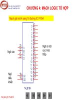
In non-equilibrium situations, the temperature of the heat source is higher, often
very much so, than the soldering temperature itself. Whether the correct soldering
temperature is reached or exceeded is a matter of timing the heat exposure. The
higher the temperature of the heat source, the steeper is the temperature rise of the
solder joint, and the more critical becomes the precise control of the duration of its
heat exposure. Overheating may not only endanger the joint and its properties, but
in severe cases it can damage the assembly itself (Figure 3.14).
Wavesoldering, vapourphase soldering, hot air or gas convection soldering,
impulse soldering and handsoldering with a soldering iron present equilibrium
Soldering 61
job:LAY03 page:44 colour:1 black–text
Figure 3.14
Equilibrium and non-equilibrium heating situations
heating conditions. Infrared soldering, laser soldering and flame soldering are
non-equilibrium systems.
Heat sources
A thermostatically controlled electrical resistance heater is the most common
primary heat source. This transmits its heat to the heat-transfer medium, whether it
62 Soldering
job:LAY03 page:45 colour:1 black–text
be the drop of solder on a soldering iron or the solderwave in a wavesoldering
machine. The reader may be amused to learn, though, that the first few wavesolder-
ing machines were gas heated.
Small, pointed butane- or propane-gas flames are used for soldering individual
joints in awkward locations. Equipment using a very hot, needle-shaped hydrogen–
oxygen flame is also commercially available. These flames, which represent extreme
cases of non-equilibrium heating, may be hand-held, but more often are manipu-
lated by programmed robots, and then of course equipped with controls which
prevent overheating.
Laser beams present the ultimate in non-equilibrium heating. To speak of the
‘temperature’ of a laser source makes no real sense; what matters is the extreme
energy density of the spot of laser light, which impinges on the joint surface, and
which may reach 10 kw per square millimetre (Section 5.6). A very precise energy
dosage is of the essence, to avoid destruction of the joint and burning a hole into the
substrate. Exposure times are measured in milliseconds.
Heat transfer mechanisms
The soldering heat can be transmitted from the heat source to the joint by any one
of three basic mechanisms: conduction, convection and radiation.
Conduction relies on a direct physical contact between a hot solid body or liquid
and the surface of one of the joint members. The efficiency of heat transfer depends
critically on the close fit between the heating and the heated surface. Any airgaps
between them fatally affect the heat transfer. Molten solder is the best heat-transfer
medium available: being a liquid, it conforms perfectly to whatever surface it has to
heat. This is the virtue of the solderwave, as well as of the drop of molten solder on
the tip of a soldering iron, which will come in very useful with repair soldering
(Sections 10.2 and 10.3). Strictly speaking, convection comes into the heat-transfer
mechanism of wavesoldering as well, because the solderwave consists of a body of
moving solder. By contrast, dipsoldering in a stationary bath relies on heat transfer
by conduction only, like a soldering iron.
3.6 Solderability
3.6.1 Wetting and dewetting
Wetting
The term ‘wetting’ describes the behaviour of a liquid towards a solid surface with
which it comes into contact. In our case,we are naturallyconcerned with the way the
molten solder behaves toward the substrate. Though everyone knows instinctively
what is meant by ‘wetting’, it will be useful to examine in detail what is involved in
wetting in the context of soldering, and how it can be quantified and measured.
Section 3.3.1 described the soldered joint as the result of a surface reaction
between molten solder and a solid metallic substrate, and it was explained why an
intimate contact between the two is a precondition for the joint to form. We must
now amplify this by saying that wetting is the precondition for this intimate contact.
Soldering 63
job:LAY03 page:46 colour:1 black–text
Figure 3.15
The wetting angle
Wetting is not a ‘yes or no’ situation; there is a scale of wetting quality between
total non-wetting and complete wetting. The yardstick for measuring the quality of
wetting is the ‘wetting angle’, which is formed between the surface of the solid and
that of the liquid along the line where they meet (Fig. 3.13 and 3.15).
A wetting angle of 180° is a sign of total non-wetting, while an angle towards zero
denotes complete wetting. In the context of soldering, a wetting angle of less than
60–75° is normally, but arbitrarily, considered acceptable; anything up to 90° is
doubtful, and beyond 90° definitely bad. Whether and when ‘bad’ can or should
be equated with ‘non-acceptable’ will be discussed in Section 9.3.
The wetting or contact angle between the molten solder and the substrate is the
result of the opposing forces of the surface tension of the solder, which tries to pull it
together into a globule (somewhat flattened by gravity), and the interfacial tension
between the solder and the substrate, which tries to pull the solder across its surface,
so that as much of the solder as possible can come in contact and react with it. The
wetting angle can be interpreted in terms of the three surface energies involved: that
of the molten solder, of the solid, and of the interface between the two. Klein
Wassink provides a detailed discussion of this aspect.
In practical terms, the significance of wetting can be stated very simply. Good
wetting helps the solder to get to all the places where it ought to be; doubtful and bad
wetting prevent the solder from entering a joint.
Dewetting
‘Dewetting’ is not the same as ‘non-wetting’. As the term implies, in a dewetting
situation the molten solder did get to where it ought to be, but it does not stay there.
Instead, it pulls back and forms separate islands of solder, with areas of exposed
intermetallic compound in between. This situation can occur in dip-tinning, e.g. in
the hot-air levelling process for circuit boards (HAL), or in wavesoldering, but only
rarely in reflowsoldering.
Dewetting is caused by local, untinnable spots of surface contamination, such as
oxide particles, or surface dirt like traces of silicones or fingerprints. Non-metallic
inclusions in galvanic coatings, for instance embedded colloids caused by unsuitable
or badly controlled plating baths for copper, nickel or gold, can cause dewetting
too.
Surfaces which dewet are at first completely covered with molten solder, which
64 Soldering
job:LAY03 page:47 colour:1 black–text
Figure 3.16
Dewetting and non-wetting
bridges the untinnable spots. Before it can solidify, its surface tension pulls the still
liquid soldercoating apart, and away from the discontinuities (Figure 3.16).
3.6.2 Capillarity and its effects
A capillary is a very thin hole or a narrow gap (from capillus, Latin for ‘hair’). If the
surfaces of the hole or gap are wettable, interfacial tension quickly pulls the liquid
solder into it with considerable force, often against the force of gravity. On the
other hand, if the inner walls of the gap are untinnable, the surface tension of the
solder prevents it from entering it.
If one of the members forming the gap is movable, like the gullwing legs of an
SMD during reflowsoldering, the interfacial tension pulls the walls of the gap
towards one another, which means it pulls the flat end of the leg into the middle of
its footprint. If, on the other hand, one or both are untinnable, the surface tension of
the solder pushes them apart (Figure 3.17).
The consequences of capillarity for soldering are important:
1. If the joint surfaces are wettable, capillarity pulls the solder into the joint, against
the forceofgravity if necessary.Ifthey wetbadly ornot atall, thesolder cannotget
into the joint, even if gravity would tend to pull it into the gap.
2. If one of the joint members is mobile, as is the case in reflowsoldering, and if
both are wettable, interfacial and surface tension pull the joint members
together. If one of them is unwettable, they are pushed apart.
In reflowsoldering, capillary forces are the cause for the self-alignment of BGAs and
small SMDs, but also for ‘tombstoning’ and the floating of chips or melfs on badly
designed layout patterns (Sections 6.4.2 and 11.2.2; also Figure 3.18).
3.6.3 Capillarity and joint configuration
Capillary joints and open joints
The way in which the solder flows into a wettable joint depends on the soldering
method and on the shape of the joint itself. Basically, there are two types of joint:
‘capillary joints’ and ‘open joints’ (Figure 3.19). With a capillary joint, or lap joint,
two flat and essentially parallel surfaces face one another, and the joint forms a
Soldering 65
job:LAY03 page:48 colour:1 black–text
Figure 3.17
two-dimensional gap. Tubular joints, like through-plated holes, are a special form
of capillary joint, where the gap is cylindrical. With an open joint, or butt joint, one
or both of the joint members are not flat, and they touch one another along a line or
just in one spot.
With capillary joints, the escape route for the air and flux in the joint can get
blocked if the molten solder closes all the edges around the joint gap before all the
air and flux inside the gap have been pushed out by an orderly, frontal advance of
molten solder into the gap from one (or at most two) sides only. With an open joint,
there is no such problem: from whichever direction the solder enters an open joint,
the escape routes for air and flux cannot be blocked.
With wavesoldering, all capillary joints, flat and tubular, fill from one side only.
Both types will normally be sound, especially the latter, unless air or water vapour
escape from the walls into the hole after the solder has entered it (blowholing),
which is a matter dealt with in Sections 9.5.3 and 11.2.2.
66 Soldering
job:LAY03 page:49 colour:1 black–text
Figure 3.18
The effects of capillarity in reflowsoldering. (a) Self-alignment of
components; (b) tombstoning
Figure 3.19
(a) Capillary joints and (b) open joints
Soldering 67
job:LAY03 page:50 colour:1 black–text
Figure 3.20
How molten solder fills a capillary joint
The penetrating speed of molten solder into a flat capillary gap between two
copper surfaces, 0.09 mm/3.5 mil apart, has been measured for various solders and at
various temperatures by McKeown (see Reference 2). At 243 °C/470 °F, using a
63% tin solder and a concentrated zinc–ammonium chloride flux, McKeown
measured a penetration speed of 3.5 sec over a gap length of 10 cm/4 in, which
equals about 2 m/6 ft per minute, the average travelling speed of a circuit board
across a solderwave.
When reflowsoldering a capillary joint with solder paste, solder and a partially
volatile flux are already in the gap before soldering starts, and entrapment of gas and
flux in the flat joint is almost impossible to avoid. The same is true for a reflowed
capillary joint, where solid solder is preplaced on one of the joint members, because
the molten solder tends to advance more quickly along the edges of a joint than in
the middle (Figure 3.20).
Only with impulse soldering, where the joint members are pressed together
during soldering, are joints less likely to be porous. Internal porosity in a capillary
joint is almost undetectable by external inspection and only shows up under X-ray
examination (Section 9.4.3). However, whether a porous capillary joint, even if it
contains up to 50% voids by volume, is really inferior to a completely solid one is
very debatable; this will be dealt with in Section 9.3.
Open joints, as which one can count not only the end-joints of melfs and chips,
but also the joints of all SOs, because their horizontal legs are short and the joint gap
is wedge-shaped, do not trap air. The few airbubbles found in such joints, if they are
sectioned, are no cause for worry. On the contrary, they are more likely to arrest
incipient internal cracks rather than starting them.
Open joints versus capillary joints
Open joints have several advantages over capillary joints in both wavesoldering and
reflowsoldering. The solder gets into them more easily, and they are much more
inspectable by optical means, unless they are partially or completely hidden under
the component housing like the J-legs of a PLCC, or underneath a BGA or a
flip-chip. The presence of solder in the joint and its wetting angle with the joint
68 Soldering
job:LAY03 page:51 colour:1 black–text
members are both readily verified. With capillary joints, the only external evidence
for adequate wetting and penetration is the continuity and the wetting angle of its
circumferential solder fillet.
Thus, a good case can be made for avoiding parallel capillary gaps and for
designing wedge-shaped, open ones instead, unless the joints are to be soldered by
impulse soldering under the mechanical pressure of a thermode. Here too, it may be
worth while considering giving the faces of the thermodes a slant, thus making the
impulse-soldered joints wedge-shaped, with any trapped flux and vapour pushed
towards one end.
3.6.4 The importance of solderability
The ease with which molten solder wets a metallic surface is called ‘solderability’. It
has a decisive influence on the achievement of both soldering success and soldering
quality, and thus on the fault rate of a soldering operation and its cost efficiency. It is
therefore important to choose joint surfaces which are inherently solderable and to
make sure that they remain in a solderable condition. To this end, one must be able
to measure, or at least to assess, their solderability.
The inherent solderability of a metal
The solderability of a metal depends on two factors: first, on the nature and the
chemical stability of the oxide layer on its surface; secondly, on the chemical affinity
between the metal and the solder, in other words on the readiness of the solder to
form a diffusion zone at its interface with the substrate.
The first factor determines whether a mild flux will do, or whether an active,
highly polar and corrosive flux is needed to remove the oxide. The chemical affinity
is based on the amount of energy set free by the reaction between the tin, more
rarely by the lead in the solder, and the substrate. The inherent solderability of a
number of common metals is shown in Table 3.14.
This listing assumes clean, though not oxide-free, surfaces. Solderability is gov-
erned by several factors, among them the following:
1. The ease with which surface oxides or sulfides are dissolved by a flux.
2. The surface energy of the metal surface (which means its readiness to react with
whatever comes in contact with it), metals with low surface energies being
more difficult to solder.
3. The metallurgical affinity between the metal to be soldered and the constituents
of the solder. For example, lead is more compatible with nickel than tin,
therefore lead-rich solders are better on nickel than pure tin or a eutectic
tin–lead solder.
3.6.5 Oxide layers
The chemical stability of the various metal oxides differs widely. Gold and platinum
do not form oxides under normal circumstances, so their chemical behaviour is
Soldering 69
job:LAY03 page:52 colour:1 black–text
Table 3.14 The solderability of common metals, listed in order of descending solderability
A. Readily solderable with mild fluxes (R and RMA)
Gold and its alloys
Tin–lead solder
Tin
B. Solderable with mild fluxes (RMA)
Copper
Silver
Copper + 2% iron
Silver/palladium (as thick-film on chips and melfs)
Gold/platinum (as thick-film on LCCCs)
C. Solderable with activated fluxes (RA)
Brass
Nickel
Cadmium
D. Solderable with active fluxes (OA etc.)
Zinc
Tin/bronze
Nickel/copper alloys
Nickel/iron alloys (Alloy 42)
Nickel/iron/cobalt alloys (Kovar)
Mild steel
Alloy steels
Beryllium bronze
E. Only solderable with special fluxes
Aluminium bronze (fluxes based on phosphoric acid)
Stainless steel (ditto)
Aluminium and its alloys (fluxes containing zinc compounds)
Cast iron (not solderable but tinnable with fluxes consisting of fused chlorides)
F. Unsolderable
Chromium
Silicon
Titanium
Manganese
irrelevant. Silver does not oxidize at room temperature, but ozone, an ingredient of
urban smog, attacks and blackens it. It readily reacts with sulfur which is always
present in our normal industrial atmosphere. The familiar brown tarnish of silver
sulfide which results from this is resistant to mild fluxes, which on the other hand
deal readily with copper oxide and zinc oxide. Iron oxide is more difficult, and cast
iron, because of the non-metallic graphite particles on its surface, is untinnable and
unsolderable by the methods admissible in electronic soldering. Chromium and its
alloys owe their resistance against tarnish to a transparent, but stable and tough,
oxide layer which makes them almost unsolderable. The oxide layer on aluminium
70 Soldering
job:LAY03 page:53 colour:1 black–text
Figure 3.21
The lift-off effect
and its alloys is equally transparent, but can be dealt with by special, though
corrosive, fluxes. On the other hand, surface oxides and sulfides of copper are
readily removed, even by mild fluxes.
A particularly obnoxious and almost unsolderable oxide layer forms if the
intermetallic compound , which is the top layer of the diffusion zone between a
copper surface and the molten solder (see Section 3.3.2, Figure 3.7), is exposed to
air. This can happen when desoldering a faulty joint or component, if the exposed
footprint is wiped clean of the solder remaining on it (Section 10.4.2). How to
guard against this mishap, and what to do if it has happened, is discussed in the
relevant section.
3.6.6 Solderability-enhancing surface coatings
Uncoated soldering surfaces, like bare copper footprints or Alloy-42 gullwings,
have become rare. Most surfaces intended to be soldered are coated with tin or a
tin–lead alloy to improve and preserve their solderability. Silver or gold are also used
sometimes, but their value as solderability preservers is doubtful. Silver is liable to
tarnish, and the presence of gold in a soldered joint can lead to embrittlement if
there is too much of it (see below).
Tin and tin–lead coatings
It is true to say that nothing is more solderable than solder itself. It is even more
solderable than pure tin, because the lead in the solder makes it more resistant to
atmospheric moisture and to corrosive environments. For that reason, a coating
with a 50% or even a 40% tin solder is often preferred to one with 60% tin.
As soon as the molten solder encounters a tin or tin–lead coating, it melts and
dissolves it. Provided the coating is thick enough, above about 25 m/0.1 mil, the
molten solder will lift off any surface contamination which might sit on the surface
of the coating, and flow underneath it. This is called the ‘lift-off effect’ (Figure
3.21).
Galvanically deposited tin–lead coatings have their problems. They consist of
discrete particles of tin and lead, and are therefore porous. All the damaging
ingredients of the atmosphere, especially an industrial one, can and will slowly
Soldering 71
job:LAY03 page:54 colour:1 black–text
penetrate between the particles down to the base metal. The tin–lead deposit
dissolves on contact with the molten solder, which is then confronted with the bare
base metal, which was originally quite clean of course, otherwise the galvanic
deposit would not have adhered to it. But after a period of unsuitable storage,
contamination might have penetrated down to it, and its solderability will have
suffered, if not disappeared.
The remedy is to fuse, i.e. to reflow, galvanic tin or tin–lead deposits in the
presence of a flux cover, and turn them into a coherent layer of tin or tin–lead solder
(Section 6.3). As a bonus, this creates a layer of intermetallic compound between the
coating and the base metal.
If the substrate base is not readily solderable with an RMA flux (like iron or an
iron–nickel alloy), a thin galvanic coating of nickel, possibly with a topcoat of
copper, must be provided between the base metal and the tin or solder topcoat.
Nickel dissolves only slowly in molten solder. While the topcoat disappears im-
mediately in the molten solder once soldering starts, the nickel survives long enough
to protect the possibly badly solderable base underneath. With a pre-fused coating,
the solder will find a ready-made intermetallic layer already in place when soldering
starts. The alternative to a fused galvanic tin–lead coating is one produced by hot
tinning, by one of the processes of roller-tinning, immersion tinning or the HAL
hot-air-levelling process (Section 6.3.1).
Silver coatings
Once popular, silver is now used less frequently, for several reasons. One is its low
resistance to unsuitable storage conditions, as described above. Another is the
danger of migration of silver between neighbouring conductors under the influence
of an electrical DC potential between them. This leads to the formation of fibrous
dendrites, which cause short circuits.
Silver dissolves relatively quickly in molten solder. If it has to serve as a solderable
coating on an otherwise unsolderable substrate, measures which are described
below must be taken in order to prevent it from disappearing before soldering is
completed.
Gold coatings
Gold as such is superbly solderable, with excellent storage properties. In spite of this,
it is rarely used because it is associated with several problems, apart from its cost.
Galvanic gold deposits, mostly 91 m/0.04 mil thick, can be almost unsolder-
able if they were produced by an unsuitable plating technique. Shiny gold deposits,
such as are used in jewellery, contain colloid additions and fall into that class. Gold
coatings thinner than 1 m/0.04 mil are liable to be porous and soon become
unsolderable.
Gold rapidly dissolves in molten solder and with 93% Au present in a joint,
large, brittle flakes of the intermetallic compound AuSn
form in the joint gap when
the solder solidifies. This situation can easily arise in a reflowsoldered joint.
For this reason, gold-coated joint surfaces should only be considered if there is a
72 Soldering
job:LAY03 page:55 colour:1 black–text
Table 3.15 Leaching rates of some substrates
Substrate Leaching rate in 60% Sn/40% Pb solder (m/sec)
at 215 °C/420 °F at 250 °C/480 °F
Au 1.7 5.25
Ag 0.75 1.6
Cu 0.075 0.15
Pd 0.025 0.075
Ni, Pt 0.01 0.01
compelling technical reason for them, or if the customer, often a military one,
insists.
The rule, established in the seventies by the European Space Agency (ESO), that
the thickness of any gold deposit on a solderable surface should bear a relation to the
width of the joint gap seems to have been forgotten, since the outerlead bonding
surfaces of TABs, which are meant to be soldered, are occasionally goldplated (see
Reference 15).
3.6.7 Leaching effect of molten solder
The rate at which a substrate dissolves in the molten solder is called the leaching rate,
and it differs from metal to metal. It depends on the rate at which substrate and
solder react with one another, on the solubility of the reaction products in the
solder, and of course on the soldering temperature. Table 3.15 lists the leaching rates
of some substrates, in descending order. The figures show that silver disappears in
the molten solder ten times and gold up to thirty times as fast as copper, and that the
leaching rate rises quickly with the soldering temperature.
The leaching effect can have serious consequences, for instance if the thick-film
solderable metallized surfaces on chips, melfs and the (now obsolescent) LCCCs
disappear, making them unsolderable. There are two ways of reducing a high
leaching rate:
1. An alloying addition. About one per cent of indium added to the solder slows
down the solution of Au in the solder. The 1.65% to 2% of Ag added to
electronic solders (Section 3.2.2) does the same for a silver substrate, but this
effect is small.
2. Modifying the substrate. An addition of up to 35% platinum to the thick-film
gold on LCCCs significantly slows down the leaching rate. Up to 20%
palladium does the same for thick-film Ag on resistors and condensers. Cheaper
and more effective, however, is a galvanically applied, leach-resistant nickel
layer, topped with a tin or solder coating for optimal solderability.
The leach resistance of components can be tested by the immersion solderability
test, described in the following section.
Soldering 73
job:LAY03 page:56 colour:1 black–text
3.6.8 Measuring solderability
The solderability of a surface is based on the speed and reliability with which it is
wetted by the molten solder using a given flux. Naturally, the milder the flux which
one wants to or must use, the higher must be the solderability of all the surfaces
involved. Solderability is one of the most important parameters in all soldering
processes, especially the mechanized and automated ones which are used in mass
soldering. The soldering success, and with it the reject rate and the economics of the
whole operation, depends on a consistently good solderability of all footprints,
lands, throughplated holes, and component wires, leads, and sintered surfaces. It is
therefore essential to have a meaningful and reproducible method for measuring it.
In the age of handsoldering, it was mainly the flux vendors who measured
solderability in order to assess the ability of their activated fluxes to cope with the
often indifferent solderability of component wires and soldering lands. With the
advent of the mechanized soldering of large numbers of joints, where soldering
times must be as short as possible, and with no-clean soldering, where fluxes should
be as mild as possible, the emphasis shifted to the soldering surfaces involved in the
process: verifying and monitoring their optimal and consistent solderability became
of paramount importance.
Uses of solderability measurement
Solderability measurement has several uses. The main one is the assessment of the
solderability of a substrate, using a flux of known and standard efficiency. The other
one is the assessment of the efficiency of a flux, using a substrate of standard and
reproducible solderability. This latter requirement is not an easy one to fulfil and it
has engaged the attention of flux manufacturers and drafting committees of standard
specifications for quite some time (Section 3.4.7). Comparing the efficiency of an
alternative flux with that of a flux with a proven performance, using components of
known and consistent solderability for reference, is a simpler proposition, and is
frequently practised in the industry.
Surfaces which need testing
Circuit boards
Given the present state of the art, the solderability of almost all commercially
available circuit boards, that is their lands and footprints, can be assumed to be good,
unless they are bare copper. In that case, a simple dipping test, which is described
later, will verify solderability. With HAL pretinned boards and reflowed galvanic
coatings, smooth and fully tinned footprints are a safe indicator of perfect solderabil-
ity. Any defects in this respect can be assumed to have been spotted by the quality
control of a competent board manufacturer.
Component leads and metallized surfaces
The solderability of components is not necessarily visually obvious. Only with
Ag/Pd sintered thick-film faces on melfs and chips, a dark grey or brown tarnish
74 Soldering
job:LAY03 page:57 colour:1 black–text
Figure 3.22
The solder meniscus and its assessment
means that sulfide has formed on them because of unsuitable storage and that they
have become unsolderable. Should that have happened with a batch of loose, not
belted, components, they can be saved by a short immersion in a photographic
fixing bath (known as ‘hypo’), or its equivalent, a 10% sodium thiosulfate solution
in water, followed by a rinse first in de-ionized water, then in clean isopropanol, and
drying off in air. Hypo is an efficient solvent for silver compounds, including the
brown sulfide.
Wetting tests
Observing the solder meniscus
The contour of the surface of the molten solder along the line where it touches an
immersed metallic body is called the ‘meniscus’. The shape of the meniscus is an
indicator of whether and how well the solder wets the metal (Figure 3.22). For a
visual check of whether all is well with a doubtful leadwire or component, looking
at the meniscus is a quick, simple test. The component lead or wire is dipped in an
MRA flux, conveniently the one which is used in production, allowed to dry for a
short while, and dipped in a small bath of 63% Sn solder held at 250 °C/480 °F (it is
useful to have such a bath handy in the quality control or production department;
see below). The meniscus formed by the solder against the immersed body is
observed visually. Opto-electronic equipment for measuring the deflection of a
beam of light focused on the meniscus has been described.
The wetting balance
The wetting balance has become the standard instrument for measuring the soldera-
bility of a metal surface, using a flux of standardized fluxing power, or the fluxing
efficiency of a flux, using a copper specimen with a surface of standardized soldera-
bility, coated with the flux under test (see Section 3.4.9). By now, it has reached a
Soldering 75
job:LAY03 page:58 colour:1 black–text
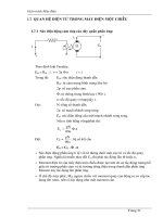
Figure 3.23
The wetting balance
high degree of technical perfection and is capable of measuring, recording and
evaluating the wetting behaviour of almost any metallic surface involved in solder-
ing. This includes the leads of all types of SMDs and the solderable endfaces of melfs
and chips. Several makes of wetting balance are commercially available. Specified
values derived from a wetting curve, produced with a flux under test, are given in
ISO 9455–16.
In principle, the test procedure is as follows. The lead, or surface to be tested, is
fluxed with a standard RMA flux and briefly dried. The test specimen is then
suspended from a sensitive balance or sensor, and immersed in an oxide-free surface
of molten solder, mostly by raising a small, thermostatically controlled solder bath
upwards against the suspended specimen (Figure 3.23), at a controlled speed. The
sensor measures the vertical force acting on the specimen. A system of micro-
processors plots this force during the test, and evaluates, prints and stores the result.
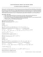
The graph of the force measured by the sensor is known as the wetting curve
(Figure 3.24). It is convenient to disregard the weight of the specimen itself, as well
as its buoyancy in the molten solder when fully immersed, which of course equals
the weight of the solder it displaces on full immersion.
What is left is a curve which first dips downwards, showing a negative weight.
This is the effect of the negative meniscus, which lasts until the specimen is warm
enough to be wetted by the solder and for the flux to begin its work. The curve then
begins to climb at a rate which is governed by the efficiency with which the flux
cleans the surface of the specimen, and thus the speed at which the solder meniscus
climbs upwards. The meniscus stops climbing, and the wetting curve flattens out, as
the final wetting angle is reached, or asymptotically approached. The force recorded
at this point, reduced to a unit of length of the meniscus, is called the wetting force.
Obviously, the blunter the final wetting angle, the lower the wetting force.
76 Soldering
job:LAY03 page:59 colour:1 black–text
Figure 3.24
The wetting curve
What the wetting balance really measures is not a mysterious force but simply the
weight of the solder meniscus, which has climbed upwards on the specimen under
the influence of the interfacial tension between solder and specimen, minus the
upwards buoyancy of that part of the specimen which is immersed in the solder.
The outer contour of the meniscus, and with it its volume and weight, are governed
by the surface tension of the solder. The mathematical law which the contour of the
meniscus follows has been calculated and described by Klein Wassink. If the
specimen tends to dewet, the meniscus will start to descend after a time, and the
wetting curve begins to drop after it has reached its maximum.
Deciding on the best method for deriving a numerical value of solderability from
a given wetting curve has been the subject of much discussion over the years.
Account must be taken of the rate of rise of the wetting curve once wetting has set
in, of its shape, of its maximum value and of the time taken to reach it. The
computer of a wetting balance is programmed to deal with it all; a detailed account
of the evaluation of wetting curves is outside the scope of this book.
The globule test
With chips, melfs, and SMDs like PLCCs, the small size and shape of the solderable
surfaces makes the measurement of the meniscus force difficult. The surfaces
concerned are small, often of complex geometry, and their buoyancy in molten
Soldering 77
job:LAY03 page:60 colour:1 black–text
Figure 3.25
The globule test
solder is greater than the wetting force which must be measured. To cope with this
situation, the ‘globule test’ (Figure 3.25) has been evolved as an alternative to the
immersion method described above.
The specimen is fluxed, dried and suspended from the measuring head of the
wetting balance. A heated anvil, normally held at a temperature of 235 °C/455 °F,
which carries a small globule of 60% Sn solder, weighing 200 mg, replaces the
solderbath. It is raised against the specimen from below until it touches the
specimen. As soon as the globule begins to tin it, the surface tension of the bridge of
molten solder, which forms between anvil and specimen, pulls it downwards. The
solderability index is calculated from the time within which the resultant wetting
curve reaches two-thirds of its maximum value (normally one-half to one second).
With chips and melfs, the solderability of both ends must be measured, because an
asymmetrical solderability can be the cause of ‘tombstoning’ (Section 3.6.2). Nor-
mally, about ten specimens, taken from a batch or belt of SMDs, are tested in this
78 Soldering
job:LAY03 page:61 colour:1 black–text
Figure 3.26
The dipping test for SMDs
manner. The solderability of single leads of PLCCs, QFPs, etc., can be measured in
the same way. A commercially available computerized wetting balance (Multi-
core) calls up the correct testing procedure and parameters once a test specimen has
been identified and placed in the machine, and automatically produces and records
its solderability value within about one minute.
The dipping test
A wetting balance is a sophisticated laboratory instrument, which represents a
considerable investment. It is used mainly by vendors of components or fluxes, and
by major users of either. The dipping test is a simple, but useful, alternative.
It is often called the ‘dip and look’ test. It does not provide a quantifiable
numerical result, but it enables the user to make a reasonably objective, unambigu-
ous judgement of the solderability of a component. It requires an electrically heated,
thermostatically controlled solderbath of about 2 kg/4 lb capacity, filled with 60%
Sn/40% Pb solder. This solderbath might well be the same as the one used in the
solderballing test for solder paste (Section 5.2.3).
The best procedure for a dipping test is as follows. At least three components
from a batch or belt are selected. The component to be tested is gripped with
stainless steel tweezers, and dipped in the flux which is used in production or, in the
case of reflowsoldering with solder paste, in an RMA flux. Excess drops of flux are
removed with a piece of filter paper, and the fluxed component is allowed to dry at
room temperature.
Immediately before the test, the surface of the solder bath is cleaned of oxide by
skimming it with a dry, clean stainless steel spatula. The fluxed test specimen is then
dipped vertically in the bath, in the manner shown in Figure 3.26. It is lowered
Soldering 79
job:LAY03 page:62 colour:1 black–text
Table 3.16 Dipping test parameters
Purpose of test Temperature of solderbath Dwell time in
solderbath
Solderability in 215 °C+/−3 °C 3 sec
vapourphase soldering 420 °F+/−5 °F
Solderability in 250 °C+/−5 °C 2 sec
wavesoldering 480 °F+/−10 °F
Tendency to dewet 260 °C+/−5 °C 5 sec
500 °F+/−10 °F
Leach resistance of 260 °C+/−5 °C 30 sec
chip metallization 500 °F+/−10 °F
Figure 3.27
Judging a dipping test result
into the bath steadily and slowly, at a speed of about 25 mm/1 in per second. It is
kept immersed under the solder for about two seconds, and then withdrawn
without jerking at about the same speed at which it had been lowered.
With a little practice, this procedure is easy to carry out. It is equally easy to
mechanize the procedure with a simple motorized device. In some countries,
simple dipping test equipment is commercially available.
80 Soldering
job:LAY03 page:63 colour:1 black–text
The test parameters depend on the soldering method by which the components
are to be used. They are tabulated in Table 3.16.
Having been dipped, every specimen is examined for signs of dewetting, under a
magnification of about ;5. If more than 95% of the surfaces of every specimen are
covered with a smooth continuous solder coating, the batch of SMDs from which
the set of specimens has been taken can be assumed to be suitable for soldering. If
more than five per cent of surface area has dewetted, the suitability of the batch of
SMDs represented by the specimens is doubtful. It will be wise to repeat the test
with a further three or more specimens. If the majority of those fail too, the batch
should not be used. It is relatively easy to estimate visually whether a dewetted area
represents above or below five per cent of the total, as Figure 3.27 shows.
3.7 References
1. Strauss, R. (1992) The Difference between Soldering Success and Soldering
Quality; its Significance for Quality Control and Corrective Soldering. Proc.
6th Intern. Conf. Interconnect. Technology in Electronics, DVS Rep. 141, Duessel-
dorf, Germany (in German).
2. McKeown, J. (1948) The Properties of Soft Solders and Soldered Joints. Brit.
Nonf. Metals Res. Assoc., Research Monograph No. 5, Wantage, UK.
3. Raynor, G. V. (1947) The Pb–Sn Equilibrium Diagram. Met. Abstr. (London),
19, p. 150.
4. Earle, L. G. (1946) The Pb–Sn–Ag Equilibrium Diagram. J. Inst. Met. (Lon-
don), 72, p. 403.
5. Smernos, S. and Strauss, R. (1984) Low Temperature Soldering, Circuit World
(Ayr, Scotland), 10(3), pp. 23–25.
6. Vianco, P. T. and Frear, D. R. (1993) Issues in the replacement of Pb-bearing
Solders. Journal of Materials, July 93, pp. 14–19.
7. Glazer, J. (1995) Metallurgy of low-temperature Pb-free solders for electronic
assembly. Internat. Materials Review, 40, No. 2, pp. 65–93 (139 references).
8. ITRI Ltd, Uxbridge UB8 3PJ, UK (from 1995 onwards) ‘Leadfree Solders &
Coatings Survey’, ‘Lead-Free Solders – References and Abstracts’, ‘Lead-Free
Solder Patents’. On-going issues of publications.
9. Fukuda, A. (1995) Eliminating Lead from PCB Solder. Nikkei Electronics Asia,
July, pp. 51–57.
10. Strauss, R. (1989) SMD Surface Mounted Devices, Verlag Technische Texte,
Bonn, Germany, p. 47 (in German).
11. Thwaites, C. J. (1986) Some Metallurgical Aspects of SMD Technology,
Brazing & Soldering (UK), Spring 1986.
12. Bader, W. G. (1969) Dissolution of Au, Ag, Pd, Pt, Cu and Ni in a molten
Tin–Lead Solder. Welding J., 12, 48, pp. 551–557.
13. Steen, H. A. H. and Becker, G. (1986) The Effect of Impurity Elements on
the Soldering Properties of Eutectic and Near Eutectic Tin–Lead Solders.
Brazing & Soldering (UK), No. 11, pp. 4–11.
Soldering 81
job:LAY03 page:64 colour:1 black–text
14. Campbell, A. N., Screaton, A. M. and Schaefer, T. P. (1955) Canad. J. Chem.,
33, p. 511.
15. Schmitt-Thomas, K. G., Lang, H P. and Moedl, A. (1993) Metallurgical
Examination of Thermally Stressed TAB Outer-lead Bonds. Conference on
‘Soldering, Science and Practice’, Techn. Univ. Munich, March 1993. DVS Rep.
153, Duesseldorf, Germany (in German).
16. Strauss, R. (1988) Wavesoldering v. Reflowsoldering – The metallurgical
consequences of the Choice of Method. Brazing & Soldering, 14, pp. 5–8.
17. Tanner, C. G. (1987) Reliability of Surface Mounted Component Soldered
Joints produced by Vapour Phase, Infrared, and Wavesoldering Techniques.
BABS Intern. Conf., Nov. 87, paper 29.
18. Ashby, F. A. and Jones, D. R. H. (1988) Engineering Materials 2. Pergamon
Press, Oxford.
19. Derived from data established by Knott, U. C. (1981) Dissertation, Structure of
Soft-soldered Joints, Techn. Univ. Munich, Germany (in German).
20. Hofmann, W. (1962) Lead & Lead Alloys. Berlin, Springer Verlag. (In Ger-
man, English translation available through Brit. Nonf. Met. Res. Assoc.,
Wantage, UK.)
21. Ashby, M. F. and Jones, D. R. H. (1988) Engineering Materials 2. Pergamon
Press, Oxford, UK.
22. de Kluizenaar, E. E. (1990) Reliability of Soldered Joints: A Description of the
State of the Art. Soldering & SMT (Ayr, Scotland), No. 4, pp. 27–38, No. 5, pp.
56–66, No. 6, pp. 18–27.
23. Engelmaier, W. (1993) Reliability of Surface Mount Solder Joints; Physics
and Statistics of Failure. Proc. Intern. Conf. Softsoldering, Munich. DVS Report
153, Duesseldorf, Germany, pp. 149–160.
24. IPC (1992) Guidelines for Accelerated Reliability Testing of Surface Mount
Solder Attachments. IPC Document IPC-SM-785.
25. Engelmaier, W. (1989) Performance Considerations, Thermal-Mechanical
Effects. Electron. Mats. Handbook, Vol. 1, ASM Intern., Materials Park, OH,
p. 740.
26. Wild, R. N. (1973) Some Fatigue Properties of Solders & Soldered Joints.
IBM Techn. Report 73Z000421.
27. Solomon, H. D. and Sartell, J. A. (eds) (1986) Electronic Packaging: Materials &
Processes, ASM.
28. Rubin, W. (1990) A No-Clean Review, Proc. Conf. Electron. Manufact. & the
Environment, Bournemouth, UK, pp. 36–43.
29. Lea, C. (1992) After CFCs? Electrochemical Publications, Ayr, Scotland, pp.
94–98.
30. Zado, F. M. (1983) Increasing the Soldering Efficiency of Noncorrosive
Rosin Fluxes. Western Electric Eng., 27(1), pp. 22–29.
31. Klein Wassink, R. J. (1989) Soldering in Electronics, 2nd ed., Ch. 5.5.3.
Electrochemical Publications, Ayr, Scotland.
32. Lea, C. (1992) After CFCs? loc. cit., p. 301.
33. Manko, H. H. (1979) Solders and Soldering, McGraw-Hill, NY, p. 313.
82 Soldering