A Practical Guide to Shaft Alignment phần 2 pot
Bạn đang xem bản rút gọn của tài liệu. Xem và tải ngay bản đầy đủ của tài liệu tại đây (3.15 MB, 10 trang )
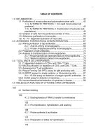
11
Expressing alignment
Angularity, gap and offset
Angularity describes the angle between two rotating axes.
Angularity can be expressed directly as an angle in degrees or in terms
of a slope in mils/inch. This latter method is useful since the angularity
multiplied by the coupling diameter gives an equivalent gap difference
at the coupling rim.
Thus the angle is more popularly expressed in terms of GAP per
diameter. The gap itself is not meaningful, it must be divided by the
diameter to have meaning. The diameter is correctly referred to as
a “working diameter”, but is often called a coupling diameter. The
working diameter can be any convenient value. It is the relationship
between gap and diameter that is important.
© 2002 PRUFTECHNIK LTD.
12
Expressing alignment
Relationship of angle, gap and working diameter.
A 6 inch coupling open at the top by 5.0 mils gives an angle between
shafts axes of 0.83 mils per inch.
For a 10 inch working diameter this corresponds to a gap of 8.3 mils
per 10 inches.
same angle - different gap
same gap - different angle
© 2002 PRUFTECHNIK LTD.
13
Expressing alignment
Offset describes the distance between rotation axes at a given point.
Offset is sometimes incorrectly referred to as parallel offset or rim
misalignment, the shaft rotation axes are however rarely parallel and
the coupling or shaft rim has an unknown relationship to the shaft
rotation axes.
As shown above, for the same alignment condition, the offset value var-
ies depending upon the location where the distance between two shaft
rotation axes is measured. In the absence of any other instruction, offset
is measured in mm or thousandths of an inch at the coupling center. (This
denition refers to short exible couplings, for spacer couplings offset
should be measured at the power transmission planes of the coupling).
6.0 mils
3.0 mils
-4.0 mils
© 2002 PRUFTECHNIK LTD.
14
Expressing alignment
Short Flexible couplings
For ease of understanding we dene short exible couplings when the
axial length of the exible element or the axial length between the
exible element is equal to or smaller than the coupling diameter.
Machines with short exible couplings running at medium to high speed
require very accurate alignment to avoid undue loading of the shafts,
bearings and seals.
Since the alignment condition is virtually always a combination of
angularity and offset, and the machine has to be corrected in both
vertical and horizontal planes, 4 values are required to fully describe
the alignment condition.
Vertical angularity (or gap per diameter)
Vertical offset
Horizontal angularity (or gap per diameter)
Horizontal offset.
Unless otherwise specied the offset refers to the distance between
shaft rotation axes at the coupling center.
The sketch below shows the notation and sign convention.
gap
angle
offset
© 2002 PRUFTECHNIK LTD.
15
Expressing alignment
Spacer Shafts
Spacer shafts are usually installed when signicant alignment changes
are anticipated during operation of the machine, for example due to
thermal growth. Through the length of the spacer shaft, the angular
change at the spacer shaft end remains small even when larger machine
positional changes occur. The alignment precision for machines tted
with spacer shafts that have exible elements at each end is not as critical
as for machines that have short exible couplings installed.
Four values are required to fully describe the alignment condition.
Vertical angle a
Vertical angle b
Horizontal angle a
Horizontal angle b
Angles are measured between the spacer shaft rotation axis and the
respective machine rotation axes.
The sketch below shows notation and sign convention
angle a
angle b
- a
- b
- a
+ b + a
+ a
- b
+ b
© 2002 PRUFTECHNIK LTD.
16
Expressing alignment
Offset B - offset A
As an alternative to the 2 angles a and b the alignment can be specied
in terms of offsets.
Vertical offset b
Vertical offset a
Horizontal offset b
Horizontal offset a
The offsets are measured between the machine shaft rotation axes at the
location of the spacer shafts ends. This is similar to reverse indicator
alignment.
The sketch shows the notation and sign convention.
offset a
offset b
+ offset b + offset a
+ offset b - offset a
- offset b + offset a
- offset b - offset a
© 2002 PRUFTECHNIK LTD.
17
Expressing alignment
Relationships
By studying the diagram below a clearer understanding of the
relationship between the various offsets and angles will be obtained.
Oset B = b x L
Oset A = -(a x L)
θ = a + b
a
b
spacer length L
© 2002 PRUFTECHNIK LTD.
18
How precise should alignment be?
Alignment tolerances for exible couplings
The suggested tolerances shown on the following pages are general
values based upon over 20 years of shaft alignment experience at
Prueftechnik and should not be exceeded. They should be used only if
no other tolerances are prescribed by existing in-house standards or by
the machine manufacturer.
Consider all values to be the maximum allowable deviation from the
alignment target, be it zero or some desired value to compensate for
thermal growth. In most cases a quick glance at the table will tell whether
coupling misalignment is allowable or not.
As an example, a machine with a short exible coupling running at 1800
RPM has coupling offsets of -1.6 mils vertically and 1.0 mil horizontally,
both of these values fall within the “excellent” limit of 2.0 mils.
Angularity is usually measured in terms of gap difference. For a given
amount of angularity, the larger the diameter the wider the gap at the
coupling rim (see page 12). The following table lists values for coupling
diameters of 10 inches. For other coupling diameters multiply the value
from the table by the appropriate factor. For example, a machine running
at 1800 RPM has a coupling diameter of 3 inches. At this diameter the
maximum allowable gap would be: 0.9 mils.
For spacer shafts the table gives the maximum allowable offset for 1
inch of spacer shaft length. For example, a machine running at 1800
RPM with 12 inch of spacer shaft length would allow a maximum offset
of: 0.6 mils/inch x 12 inches = 7.2 mils at either coupling at the ends
of the spacer shaft.
Rigid couplings have no tolerance for misalignment, they should be
aligned as accurately as possible.
© 2002 PRUFTECHNIK LTD.
19
How precise should alignment be?
Suggested alignment tolerance table
© 2002 PRUFTECHNIK LTD.
20
How precise should alignment be?
Note
For industrial equipment the amount of misalignment that can be
tolerated is a function of many variables including RPM, power
rating, coupling type, spacer length, design of coupled equipment and
expectations of the user with respect to service life. Since it is not
practical to consider all these variables in a reasonably useful alignment
specication, some simplication of tolerances is necessary.
Tolerances based on RPM and coupling spacer length were first
published in the 1970’s. Many of the tolerances were based primarily
on experience with lubricated gear type couplings. Experience has
shown however that these tolerances are equally applicable to the
vast majority of non lubricated coupling systems that employ exible
elements in their design.
In the previous table “acceptable” limits are calculated from the sliding
velocity of lubricated steel on steel, using a value of 0.5 inch/sec for
allowable sliding velocity. Since these values also coincide with those
derived from elastomer shear rates they can be applied to short exible
couplings with exible elements.
“Excellent” values are based on observation made on a wide variety of
machines to determine critical misalignment for vibration. Compliance
with these tolerances does not however guarantee vibration free
operation.
© 2002 PRUFTECHNIK LTD.