Advances in the Bonded Composite Repair o f Metallic Aircraft Structure phần 2 potx
Bạn đang xem bản rút gọn của tài liệu. Xem và tải ngay bản đầy đủ của tài liệu tại đây (1.53 MB, 59 trang )
Chapter
2.
Materials selection and engineering
23
If the problem causing the need for the repair was fatigue or corrosion, it may
be more appropriate to use
a
composite for the repair as these materials are
effectively immune to these problems (composite repair layups generally have fibre
dominated properties which are immune to fatigue whereas layups with matrix
dominated properties may be susceptible to fatigue). The repair material chosen
can also
be
important where subsequent inspections are required and in many
cases the use
of
boron/epoxy composites is advantageous as eddy current methods
can be used to readily detect the crack underneath the repair. This is usually more
difficult if a metallic or graphite fibre patch is used due to the fact that these
materials are electrically conducting. Metallic materials will require the use of
stringent surface preparation and surface treatment processes to obtain a durable
bond, however, if a corrosion inhibiting primer is used, these processes could be
conducted elsewhere and the patch stored prior to use. Composite repairs using
thermosetting matrices such as epoxies are comparatively easier to prepare for
bonding, although the processes required are still important
[2].
Thermoplastic
composites are in general harder to bond to than the more commonly used
thermoset composites. Finally metals lend themselves best to relatively flat repair
locations due to the difficulty in accurately forming a metallic sheet to a curved
profile. This is one of the strengths of composites where the desired shape can be
formed into the repair during cure.
Further considerations for the selection of a metallic material may include
corrosion and patch thickness. To avoid galvanic corrosion problems between
dissimilar metals, a sensible choice would be to use the original material for the
repair material as well. Where this is not possible, a check should be made to ensure
that different repair materials would not be susceptible to corrosion. For example,
repairs to a graphite/epoxy component will often
be
performed with a graphite/
epoxy material as well. Use of an aluminium material in this situation would be
unusual as the aluminium will readily corrode if in galvanic contact with the
graphite fibres. The adhesive should serve as an electrically insulating layer,
however, the more usual alternative to a graphite patch in this situation would be
titanium which will not corrode should the insulation break down.
In situations where the thickness
of
the repair is critical (on an aerodynamic
surface for example) consideration may be given to either steel or titanium to repair
aluminium. The greater stiffness of these materials should permit the design of a
thinner patch than would
be
possible with aluminium. Again consideration should
be
given to possible galvanic coupling and potential corrosion problems in this
situation and it is possible that the choice of a composite may be preferable.
Laminated metallic materials have been developed in the Netherlands which
consist
of
layers of composite sandwiched between thin aluminium alloy sheets
[3].
Where the composite used
is
kevlar (or aramid) the laminate is referred to as
ARALL (aramid reinforced aluminium laminate) and if the composite used is glass
fibre, the laminate is referred to as GLARE (Chapter
14).
The fundamental idea
behind the development of these materials is to combine the traditional advantages
of both metals and composites. The composite component confers increased fatigue
strength and damage tolerance to the structure, while the aluminium allows the use
24
Advances in
the
bonded composite repair
of
metallic aircraft structure
of conventional metallic forming, fastening and manufacturing processes for
reduced cost.
GLARE
has been proposed as a possible material for use in bonded repairs and
in particular has been used as
a
material for the repair of damage to the fuselages of
transport aircraft. The principal advantage of
GLARE
in this situation is the high
coefficient of thermal expansion. Work by Fredell
et al.
[4]
and Chapter
14,
has
shown that for repairs to thin fuselage skins which will mostly see pressurisation
loads at cruising altitudes
(-55
"C), the higher coefficient of thermal expansion of
GLARE
provides structural advantages compared with composite alternatives (see
Section
2.6
for further discussion). On the other hand the low specific stiffness of
GLARE
results in a much thicker patch than for
a
high modulus composite
material, and this needs to be carefully considered in the design to ensure that
bending effects due to neutral axis offset are not excessive and that high stresses at
the ends of the patch are alleviated by tapering for example.
Finally, it may be possible to use nickel as a repair material in some specific
circumstances for example where geometry is complex. The repair of a crack in the
comer
of
a bulkhead pocket is a good example. Nickel can be electroformed to
replicate the surface of a mould with very high precision, and therefore it should be
possible to produce an electroformed nickel patch which will fit precisely into the
pocket.
As
mentioned above, the isotropic nature of the nickel would be an
advantage in this situation, although care needs to be made to ensure that the
electroforming process does not produce planes of weakness within the electro-
form. Work
is
underway to evaluate this method as a repair option for a damaged
army gun support structure
[5].
In situations such as this where a certain degree
of
rough handling can be expected, the hard, damage resistant surface
of
the nickel
provides another important advantage over a fibre composite repair.
2.2.2. Non-metallic materials
The two main non-metallic materials used are boron/epoxy and graphite/epoxy
composites. Glass fibre composites are not used due to their low stiffness and
kevlar composites while strong and stiff in tension have relatively poor
compression performance.
Boron fibres were first reported in 1959 and were the original high modulus fibre
before the development
of
graphite fibres in the 1960s. Boron composites were used
to produce aircraft components such as the skins of the horizontal stabilisers on the
F-14 and the horizontal and vertical stabilisers and rudders on the F-15. The use of
boron composites in large-scale aircraft manufacturing has largely stopped now
due to the development of more cost-effective graphite fibres. The production
process for boron fibres is time consuming and does not lend itself to mass
production in the same way as modem methods for producing graphite fibres. For
this reason the price of boron fibres has not dropped as significantly as that of
graphite fibres which are
now
at around
I/lOth the cost. Boron fibres are
manufactured individually by chemically vapour depositing boron onto a heated
tungsten wire substrate from boron trichloride gas in a reactor. The fibres are
Chapter
2.
Materials selection and engineering
25
available from Textron Speciality Materials in 100 and 140 micron diameters and
commercial pre-pregs are available with either 120°C or 175°C curing epoxies. The
fibre diameter is significantly larger than normal graphite fibres due to the presence
of the tungsten core. Attempts have been made in the past to use a carbon filament
precursor to reduce the production costs, however, these boron-carbon filaments
have generally not had the high level of strength that can be produced with the
tungsten filament precursor.
Boron fibre is an extremely hard material with a Knoop value of 3200 which is
harder than tungsten carbide and titanium nitride (1800 -1880) and second only to
diamond
(7000).
Cured boron composites can be cut, drilled and machined with
diamond tipped tools and the pre-pregs are readily cut with conventional steel
knives. In practice the knives cannot actually cut the hard fibres, however, gentle
pressure fractures the fibres with one or two passes. “Snap-off’ knife blades are
commonly used as the cutting edge is rapidly worn by the hard fibres. Although it is
possible to cut complex shapes with the use of templates, laser cutting has been
shown to be the most efficient way to cut a large amount
of
non-rectangular boron
plies. Circular patches, for example, are readily cut using a laser cutter with the pre-
preg supported on a backing material such as Masonite.
The combination of very high compressive stiffness, large fibre diameter and high
hardness means that boron fibres can readily penetrate skin and care must be
exercised in handling boron pre-preg to reduce the chance
of
splinter-type injuries.
If a fibre does enter the skin, it should
be
removed very carefully with he tweezers.
Trying to squeeze the fibre out must be avoided as the fibre may fracture into
smaller segments.
The stiffness and diameter of boron fibres also restricts their use in small radius
corners. The 100 micron diameter fibre can be formed into a radius of
30
mm, but
this is about the limit than can be comfortably achieved. The smaller diameter of
graphite fibres makes it the choice for smaller radii situations. In most other
aspects, boron pre-pregs handle and process in a similar fashion to the more
common graphite pre-preg materials.
As a repair material, boron/epoxy composites have a number of advantages
[
1,6]
including;
0
an intermediate coefficient of thermal expansion which helps to minimise the
level of thermally induced residual stress which results from an elevated
temperature cure. This contrasts with graphite fibres mentioned below.
0
relatively simple
NDI
is possible using eddy currents through the repair patch to
detect the extent of the defect. This is possible due to the non-conducting nature
of the fibres.
0
no galvanic corrosion problems when bonded to common airframe materials.
0
a good combination of high compressive and tensile strength and stiffness (the
compressive strength of a unidirectional B/EP composite is 2930 MPa compared
with 1020MPa for
HMS
GR/EP)
Graphite fibres are now available in a very wide range of properties and forms and
improvements in manufacturing processes has seen the cost of the fibres reduce
over the past
25
years. Although the fibres are not as hard as boron, the cured
26
Advances
in
the bonded composite repair
of
metallic aircraft structure
composites are very abrasive and diamond tipped tools are normally used for
cutting or machining. The fine graphite laden dust from such operations is believed
to be a health hazard and
so
measures to control this hazard must be taken. This
electrically conducting dust can also cause problems with electrical equipment if it
is not removed and filtered from the room air. Graphite pre-pregs are commonly
available as 120°C and 175°C curing systems and lower temperature cure resins are
also available now for use in repair situations.
Graphite fibre is an unusual material in that it has a slightly negative coefficient
of thermal expansion, which means that the fibres contract slightly in the axial
direction when heated. This results in relatively high levels
of
thermally induced
residual stress if the cured composite is bonded to the structure with an elevated
temperature curing adhesive.
As
well, the fibres are electrically conducting and will
cause galvanic corrosion of aluminium if the two are in electrical contact. Due to
the electrical conductivity it is more difficult to use eddy-current NDI methods with
these materials to check the position of a crack under the patch for example.
Graphite composites are significantly cheaper than boron composites and are
available from a very wide range of suppliers. They offer a wide range
of
properties
for design and with epoxy resin matrices are readily processed and can be cured to
complex shapes
to
suit the damaged structure. If a repair is required to a tight
comer with a small radius, graphite fibres would be preferred to boron as
mentioned above.
Repairs to aircraft are usually weight critical and
so
the specific properties of the
various repair materials are therefore
of
interest. Table
2.2
compares the mechanical
and thermal properties
of
some candidate patch or reinforcing materials. This
comparison includes boron/epoxy (b/ep) and graphite/epoxy (gr/ep), the metal/
composite laminates
GLARE
and
ARALL
and typical high-strength aluminium
and titanium alloys
-
which also represent the metals to be repaired.
2.2.3.
Patch material selection
Many of the criteria for selection
of
a successful repair material have been
discussed in the above two sections. The reader is referred to Sections 2.1 and
2.2
for a complete discussion of the issues and in this section a summary of the main
points is given referring to the four main repair materials and some
of
the main
design issues that are commonly faced.
0
Patching efficiency: High tensile stiffness is required to minimise the crack
opening displacement after repair and therefore keep the stress intensity and
crack growth down. The fibre composite materials are naturally more efficient
than either the conventional or laminated metallic materials (refer Table
2.2
for
specific stiffness i.e. modulus divided by destiny).
0
Operating temperature: For sustained high temperature operation over
1
50"C, a
titanium patch may prove to be the best solution. Conventional aluminium
alloys and the laminated metals would need to
be
carefully investigated as there
are a range of upper temperature limits depending on the
alloy
and heat
treatment involved. In general, most aluminium alloys could withstand extended
Chapter
2.
Materials selection and
engineering
21
Table
2.2
Relevant materials mechanical and physical properties for component and patch materials.
Thermal
Shear Critical Fatigue expansion
Modulus modulus strain Strain Density coefficient
Material GPa GPa
x
10-~
x
10-~
(g/cm3)
oc
x
IOP
Aluminium alloy
Aluminium alloy
Titanium alloy 6
Boron/epoxy b/ep
(unidirectional)
Graphite/epoxy gr/
ep (unidirectional)
Aluminium laminate
GLARE
2
Aluminium laminate
ARALL
3
Electroformed
Nickel
1015
T6
2025 T3
A1/4V
12
12
110
208
max
20
min
148
max
12
min
65
68
201
21
21
41
1
5
na
na
16
6.5 3.3
4.5 3.3
8.8 6.8
7.3
1.0
13 12.0
5.2 3.3
8.9 3.3
1.7-3.4
na
2.8
2.8
4.5
2.0
1.6
2.5
2.3
-9
23
23
9
4.5
min
23
max
-
0.3
min
28
max
-
15
-
16
13
Notes: (a) Maximum modulus and minimum expansion coefficient are in the fibre direction, other values
are for the transverse direction,
(b)
shear modulus values for the composite are for through-thickness
deformation, (c) critical strain refers to failing strain for the composites and yield strain for the metals,
(d)
fatigue strain refers to approximate strain for crack initiation at
lo6
cycles, R
-
0.
periods at 120°C, which
is
slightly higher than the normal operating temperature
of
105°C
for a
175°C
curing composite pre-preg. Higher temperature curing
resins are available for composites, although the availability is not as high and
depending on the system involved, processability may be reduced.
0
Residual stress: If a repair (cured at elevated temperature) is likely to see
extended service at
low
temperatures (for example a fuselage repair to a transport
aircraft
-
[4]),
the best choice may
be
either a conventional or laminated metallic
material where the coefficient of thermal expansion
is
more nearly matched to
the structure. In this situation, graphite/epoxy repairs and to a lesser extent
boron/epoxy repairs will result in higher levels of thermally induced residual
stress
[7].
0
Cost: Although not usually a major driver, conventional metallic materials
would offer the lowest material costs, followed by the laminated metals, graphite
composites and the boron fibre composites are the most expensive. Analysis of
repair costs need to be done carefully as often a composite repair may prove to
be cheaper than a metallic repair despite greater material costs.
This
is largely
due to the excellent formability of composites and the reduced time required to
form the repair patch to the desired shape.
0
Inspections:
If
full use is made of the benefits of bonded repair technology and
the defect
is
left in the structure under the repair, it
is
likely that future non-
28
Advances
in
the bonded composite repair
of
metallic aircraft siructure
destructive inspections will
be
required to confirm that the defect has not grown
significantly in size. Boron composites are well suited to such circumstances, as
the routine use of eddy currents will detect the presence of fatigue cracks for
example under the patch. The detection of defects with eddy currents under
highly curved boron repairs is more difficult as is the detection of defects under
any sort
of
graphite repair due to the conductivity of the fibres. Detection of
defects under bonded metallic repairs can be difficult and may involve the use
of
X-rays
or
ultrasonics.
0
Weight: If the repair is to be made
to
a
weight critical component such as
a
flight
control surface, materials with the highest specific properties are desirable. The
composite materials will enable repairs with greatly reduced weight compared
with the metallic materials. This same point
is
also of relevance where
aerodynamic smoothness is important. Composite repairs will typically be one-
third the thickness of an aluminium repair and
so
will provide significantly less
drag.
2.3.
Adhesive
systems
Adhesive technology has undergone rapid growth over the past
50
years and
adhesives are now widely used in markets such as automotive, aerospace,
construction, packaging and consumer appliances. Most common adhesives can
be usefully categorised as belonging
to
one or more of the following classes;
structural, hot melt, water-based or pressure sensitive. Of these only the structural
class is
of
interest in this book. Structural adhesives are defined as those adhesives
capable of withstanding significant loads and capable of bonding together
adherends also capable of carrying significant loads. For the purposes
of
this
book, shear strengths
of
10MPa would be seen as the minimum requirement.
2.3.1.
Adhesive
types
Within the structural adhesive class are a number
of
adhesive types based on
chemistry. The most important are epoxies, modified acrylics, polyurethanes,
cyanoacrylates, anaerobics, phenolics and polyimides. Anaerobics cure in the
absence of oxygen by free radical polymerisation and are widely used in threaded
assemblies to prevent loosening
of
nuts. They can develop high shear strengths but
generally have limited temperature capability and are not used for Bonded Repairs.
Cyanoacrylates cure due to the presence of water molecules on the adherends which
act as initiation sites for polymerisation. They have excellent shear strength but are
comparatively brittle with poor peel strength, are not suitable for filling gaps and
are degraded by moisture. Relatively high shrinkage stresses on cure also mitigate
against their use in Bonded Repairs. Polyurethanes have good toughness and
flexibility, but tend not to have the high shear strength and temperature capabilities
that are required for bonded repairs. Phenolic adhesives were the original structural
adhesives used in aircraft construction but tended to be very brittle until the
Chapter
2.
Materials selection and engineering
29
introduction of modified phenolics (the “Redux” adhesives) which had higher peel
strength. Phenolic adhesives exhibit excellent bond durability and the modern
nitrile modified phenolics are widely used in a range of demanding applications.
In
general, however, they require high cure temperatures and pressures which may be
difficult to accommodate in a repair situation. The other main structural adhesives
are those capable of very high temperature operation such as the polyimide
(PI)
or
bismaleimide
(BMI)
adhesives. These could be considered in specialised repair
applications, however, compared with epoxies or acrylics they tend to be difficult to
cure.
The two adhesive types used most successfully for Bonded Repairs are the
epoxies and modified acrylics. The properties of these adhesives are discussed in
greater detail in the next section. Acrylics are normally produced in paste form,
however, epoxies are commonly available in both paste and film versions. Film
adhesives have the resin and curing agents pre-mixed at the factory and are then
coated onto a thin carrier cloth or scrim in the form of a thin film. The advantages
of this are that mistakes can’t be made in mixing the correct ratio of hardener, the
film makes it easy to achieve uniform thickness bondlines and film adhesives are
much easier to apply and handle than pastes. Disadvantages are increased cost and
the resin is effectively curing as soon as the hardener is mixed and therefore film
adhesives must be refrigerated to provide a reasonable shelf life.
2.3.2.
Adhesive properties
Epoxies come in a very wide range of formulations and types but are generally
characterised by high levels of strength, good temperature capability, low shrinkage
stresses on cure and the ability to form durable bonds. Epoxies are normally
considered to be the most expensive of the common adhesive types (although are
not as expensive as the high temperature polyimides). The ability to form durable
bonds is highly dependent on the level of surface treatment that is applied to
metallic adherends in contrast to the behaviour of acrylic adhesives. The
temperature capability of the adhesive is dependent on the cure temperature and
so
for repairs to structure that sees high temperatures, an elevated temperature cure
is required.
Room
temperature curing epoxies are commonly available in paste
form (usually two components) and these adhesives can often provide moderate
temperature capability with a post cure to above the operating temperature. Some
pastes can also provide higher temperature capability, however, for service at
100°C
or higher, film adhesives are commonly used. Unmodified epoxies are
inherently brittle materials like phenolics and
so
most commercial systems are
modified with the addition of the toughening agent which is commonly an
elastomer.
Modified acrylics or second generation acrylics were developed during the
1960s
from the original acrylics which were too brittle to be of practical use in structural
joints. The rubber toughened acrylics have good shear and peel strengths although
the shear strengths are generally not as high as those of the epoxies. They usually
cure rapidly at room temperature, in some cases within
1
to 2min, and they have
30
Advances in the
bonded
composite repair
of
metallic aircraft structure
the ability to readily bond a range of different adherend materials. The ability of
these adhesives to develop good adhesion strengths with limited surface treatment
is due to the acrylic monomer which is a free flowing liquid of low surface tension.
Modern acrylics are able to produce strong, durable bonds to unprepared
aluminium and steel surfaces; epoxy adhesives are unable to achieve this.
Commercially available systems now do not require mixing of two components
but instead can use an activator applied to one adherend and the adhesive to the
other which simplifies the use compared with two-part epoxies. Disadvantages
include an odour that some people find objectionable, limited temperature
capability and limited pot life which can be a problem for larger repairs. Acrylics
are widely used in industrial applications where the ability to rapidly bond poorly
prepared steel sheet is an important advantage and is able to replace the
use
of spot
welding or riveting.
2.3.3.
Adhesive selection
The designer of a bonded repair has a very wide range of adhesives to choose
from, although in practice the selection is usually made from those adhesives that
are readily available to the company. The two most important selection criteria are
temperature and load carrying capability. A conservative approach is to use an
adhesive for the repair of equal temperature capability to the original structure.
This is typically 120
"C
cure for commercial (subsonic) aircraft and 175 "C cure for
military (supersonic) aircraft. However, the use of a 175
"C
curing adhesive during
manufacture does not necessarily mean the structure will be exposed to such high
temperatures. Often a 175
"C
adhesive is used in manufacture to be compatible with
the 175°C curing pre-preg
so
that the part can be cured and bonded in one
autoclave cycle. If the actual operating temperature of the component can be
shown to be 60°C for example, it is possible to produce
a
sound repair with a
120 "C curing adhesive.
It should be noted that the use of 175 "C curing adhesives for repair has in itself
caused significant problems when the structure to be repaired contains honeycomb
core and water is present within the core. At around
140
"C, the pressure generated
inside the core by the air and water exceeds the flat-wise tension strength of the skin
to core adhesive and the skin can be disbonded by the pressure. The risk of such
damage occurring is greatly reduced at 120°C and at least one adhesive
manufacturer has developed a 120°C version of the standard 175°C adhesive
system for use during repair to honeycomb structure.
Bond durability (particularly for epoxies) is generally related to cure temperature
and it is common to find excellent bond durability for 175°C systems, good
durability at
120
"C but only fair to good durability for room temperature curing
adhesives. The improvement in durability for the 175
"C
cure, however, needs to be
weighed up against the other problems which can develop such as blown skin to
honeycomb
core
bonds and increased thermally-induced residual stresses.
The required load carrying capacity of the adhesive needs to be carefully
considered. Some manufacturers of structural adhesives are now beginning to
Chapter
2.
Maierials selection
and
engineering
31
provide design data in the form of shear stress/shear strain data. The more common
lap shear strength is not suitable for use in a bonded repair and is generally only
useful in comparing one adhesive to another. Details of the data that is required for
design based on adhesive properties is given in Chapter
4,
and
if
it is necessary to
generate this data, appropriate test methods are described in Section
2.5
and
Chapter
4.
Two key parameters are the shear strength and plastic strain to failure.
The adhesive needs to have sufficient shear strength
so
as not to yield excessively
under the design loads, and care should
be
taken in designing with relatively brittle
adhesives which cannot provide a soft, yielding type of failure under
high
loads.
Less well understood is the ability of the adhesive to withstand through-thickness
stresses, i.e. those perpendicular to the plane of the joint. Conventional design
wisdom with adhesive joints is to eliminate such stresses by the use of different
design techniques. In many cases it is possible to eliminate or greatly reduce the
magnitude of these stresses simply by the use of sensible design features such as
tapering of the end of the repair. In some circumstances, however, it is not possible
to reduce these stresses and some examples are given in Chapters
30
and
33.
In
repairs to structure involving a high degree of curvature, the question then becomes
one of determining the capacity of the adhesive to withstand the through-thickness
or peel stresses that are present. There is currently no generally agreed test method
to generate design data for this situation, although a novel test specimen has been
proposed which may be suitable for this purpose
[8,9].
Any repair design where
high levels of peel stress are likely to be present needs to be very carefully
considered and would be expected to require extensive analysis and experimental
validation for certification. The work described in
[8]
is aimed at increasing the
understanding of the performance of adhesives under peel stresses, however, while
this may lead to some easing of certification requirements, the sound engineering
practice will continue to be to design peel stresses out of an adhesive joint where
ever possible.
Other criteria which may be important in the selection of a repair adhesive could
be availability and the ability to cure at low temperatures. Availability and the
requirement for refrigerated storage could be important at some forward Air Force
bases for example, where only a very limited range of adhesives may be available at
short notice. When rapid repairs have to be made in primitive conditions, for
example to battle damage, it may not be possible to provide refrigerated storage
and therefore only two-part adhesives would be available.
As
described in Section
2.6,
thermally-induced residual stresses are produced when the repair material has a
different coefficient of thermal expansion to the substrate and an elevated
temperature cure is necessary. The obvious way of reducing the level of such
stresses is by reducing the cure temperature of the adhesive as much as possible.
Some adhesives are able to cure at temperatures lower than their advertised cure
temperature although this is not always the case
[lo].
Film adhesives are often sold
as either
120
"C or
175
"C
curing systems (partly for compatibility with other pre-
pregs
etc.),
however, a careful examination of the thermodynamics
of
cure can
indicate that the optimum cure temperature is different from these advertised
temperatures. Considerable care must be taken if a decision is made to cure at
32
Advances
in
the bonded composite repair of metallic aircraft strucmre
temperatures other than those advertised to ensure that other properties are not
compromised.
The ability of the adhesive to remain durable in the operating environment is
normally of critical importance and consideration may need to be given to the
influence of solvents or chemicals which the adhesive may be exposed to. For
example some repairs have been applied inside aircraft fuel tanks or in regions
where the adhesive is exposed to hydraulic oil. Most epoxies and acrylics have very
good resistance to solvents and chemicals and
so
these types of exposures have not
been of major concern to date, but do need to be checked on an individual basis
Where possible it is recommended that repairs are cured under positive (as
compared to vacuum) pressure and further details are given in Chapter
25.
When
the use of vacuum bag pressure is the only alternative, consideration may need to
be
given to the void content in the cured adhesive bondline (Section
6.2).
Some
adhesives do not cure well under vacuum and heavily voided bondlines can result.
There is some evidence to suggest that moderate amounts of voids do not adversely
affect fatigue strength, however, in general significant void contents in structural
adhesive bondlines are to be avoided.
v11-
2.4.
Primers
and coupling agents
A range of different chemicals may
be
required for effective surface preparation
and a detailed scientific discussion of these is given in Chapter
3.
This section will
look at some
of
these chemicals from a materials engineering perspective and
consider some of the common factors that may
be
need to
be
considered in the
overall design of the repair.
From Section 2.1 it is clear that significant attention must be paid to the surface
treatment of metallic adherends prior to bonding if a strong, durable adhesive bond
is to be produced. There are two major types
of
treatments for aluminium alloys
that for historical reasons have developed in Europe and North America. In
Europe, the preferred treatment is the use of a chromic acid etch to produce a
hydration resistant oxide, whereas in North America the use of phosphoric acid is
preferred. Both treatments have been used successfully in aircraft manufacturing
and are capable of producing highly durable bonds. Components are dipped into
tanks of acids and other chemicals in the factory to produce the required oxide
structure for bonding. The difficulty comes in transferring this technology to a
repair situation. For example when acids are used on an assembled aircraft
structure, care must
be
taken to completely remove the acids or corrosion may
result. Boeing in particular have developed procedures whereby the same
technology as used
in
manufacturing can be applied to some repairs. The
phosphoric acid containment system (PACS) uses vacuum bags over the repair site
to
transport the acid across the surface. This contains the acids to minimise health
and safety concerns and permits a final flush with water to remove the acid from the
aircraft surface. The anodisation is carried out under the bag as well. This
Chapter
2.
Materials selection
and
engineering
33
procedure can produce bonds with durabilities close to the best factory treatment
such as a full phosphoric acid anodisation (PAA). While this process can be highly
effective, it requires specialised equipment, it is relatively complicated to perform
and cannot be used in many repair situations.
A
common requirement in repair situations is for a surface treatment method
which is simple to use, preferably does not require use of anodisation (the electrical
voltage of which can create a hazard inside wing tanks for example) and does not
use chemicals that could cause harm to either the operator or aircraft. In some
situations a repair must be applied to two different materials at the same time and
so
the ability to treat both metals at the same time can be an advantage. The
use
of
silane coupling agents can meet all of these requirements. Silanes are well known as
adhesion promoters and are bi-functional molecules containing polar silanol
groups and organofunctional groups capable of reacting with the chosen adhesive.
The silanol group forms a strong bond with the oxide surface that is hydrolytically
stable, and the organofunctional group forms a strong bond with the adhesive. It is
of
course important to choose a silane that is compatible with the adhesive being
used. Silanes are available for both epoxy and acrylic adhesives.
The use
of
silanes as a coupling agent is advantageous in a repair situation for
several reasons. Silanes do not cause any damage to the surrounding structure if
they are not completely removed following application. They are very simple to
apply requiring only hydrolysation prior to use and can be applied simply with no
special equipment required. They are relatively safe to use, although care must be
taken to avoid ingestion and contact with the eyes. Silanes can effectively treat a
range
of
different materials thereby greatly reducing the complexity of the repair
application. Finally they are very effective as coupling agents and can produce
adhesive bonds with durabilities close to that produced by the factory
PAA
treatments.
Further improvement in the bond durability can be achieved with the use
of
a
corrosion inhibiting primer after the application of the silane or other surface
treatment. Primers are normally dilute polymeric solutions which are usually
sprayed onto the bonding surface and are able to easily wet the surface. If the
surface has been roughened by abrasion, the primer is able to flow easily over the
surface irregularities to provide a thin polymeric layer in intimate contact with
and having strong bonds with the surface. The polymer is chosen to readily bond
to the repair adhesive and is often the same type of polymer. Primers commonly
require a period after spraying to enable volatiles to evaporate before the primer
is cured at elevated temperature.
A
surface primed in this way can be stored for
several months prior to bonding, requiring only a careful solvent wipe to remove
surface contamination prior to bonding. The primer will often contain fine
chromate particles which help to prevent the hydration of the adjacent metal
oxide layer. The chromate particles are however toxic and care must be taken in
the use of such primers. The thickness
of
chromated primer layers for use in an
adhesively bonded joint is also important and care must be taken to follow the
manufacturers’ directions and not to build up too much thickness in the sprayed
layer.
34
Advances in
the
bonded composite repair
of
metallic aircraji structure
2.5.
Adhesive
and
composite test procedures
There are a wide range of test procedures that are directly applicable to adhesives
and composites and these range from quality assurance type tests to chemical and
physical tests to measure adhesive properties to static and fatigue tests aimed at
generating mechanical design data. Mechanical tests are covered in Chapter
4,
where the use of the thick-adherend lap shear test is described to generate adhesive
shear stress and shear strain data. Also in this section is
a
description of the skin
doubler specimen for fatigue testing and the double cantilever beam specimen for
Mode
1
fracture toughness.
An important test for quality assurance is the flow test that measures the ability
of the adhesive to flow when heat and pressure are applied. This is particularly
important for film adhesives where the catalyst and resin are pre-mixed in the
factory and
so
the adhesive is effectively curing all the time. As described in Section
2.3.1,
iilm adhesives require refrigeration to ensure the curing reaction is reduced to
a level where the adhesive has a reasonable shelf life. When stored under the
appropriate conditions, the shelf life of the adhesive should be as specified by the
manufacturer. If there is any doubt as to whether the adhesive may have cured or
“advanced” too far to be
of
use, a flow test can be performed. There are many
forms
of
flow tests in existence and a typical example is that specified in [12]. In this
test, discs of film adhesive are punched from the film and subjected to heat and
pressure in a controlled manner. The adhesive flows and cures and the degree of
flow is measured as a function of the increase in perimeter or area. Flow of an
adhesive drops rapidly as the adhesive crosslinks and it is possible to set flow
criteria beyond which the adhesive is deemed to be no longer useable.
As
described
in Section 2.1.1, it is essential for the adhesive to flow during the cure to adequately
wet the adherends and produce high bond strengths. The advantage of the flow test
is that it is relatively simple to perform and does not require particularly
sophisticated equipment.
A
similar result can be obtained from chemical tests such
Differential Scanning Calorimetry in which the amount
of
unreacted epoxide is
measured. Tests such as these are perhaps more precise than a flow test, but require
sophisticated equipment and skilled operators to perform the tests. Although
simple mechanical tests such as lap shear strength have been used to determine
whether an adhesive is still in life, this property is not very sensitive to overageing
and
so
the much more sensitive flow measurement
is
to
be
preferred.
When film adhesive is used for a repair, there are often good reasons to
deliberately advance or “B-stage” the adhesive prior to cure
(see
Section 2.6.2 for
details). Where this is done it is very important to ensure that the adhesive is not
B-
staged to the extent that flow is compromised. A flow test can be used to confirm
that sufficient flow remains in the adhesive after the B-staging process. Using this
method, a B-staging time of
45
min at
80
“C has been proposed for use with fresh
FM73 adhesive
1131.
Note that the B-staging conditions will change as the adhesive
stock ages. B-staging for
45
min at
80
“C
will not be appropriate for FM73 adhesive
which exhibits only marginal flow in the un B-staged condition. One way of
managing film adhesives (for repair situations) is to always use the adhesive in
Chapter
2.
Materials selection
and
engineering
35
the same flow condition. When the adhesive stock is fresh, the adhesive may require
considerable B-staging prior to use, but the amount of B-staging will reduce
progressively as the stock ages, until the flow limit is reached. At this time the
adhesive could be used without B-staging, but any further ageing of the stock
would take it over the flow limit and would require that stock to be scrapped.
If a composite material is being used for the patch, a simple test to confirm that it
is within life and is suitable for use is the interlaminar shear (ILS) test or short
beam shear (SBS) test. One form of this test is described in ASTM
D2344.
As for
the flow test, the test is relatively simple to perform and only requires a small
amount of material and mechanical testing equipment. This test measures the
interlaminar shear strength of a small sample of the material, and this strength is a
resin dominated property. If the resin in the pre-preg is too advanced, the pre-preg
will not flow adequately during cure and high shear strengths between the laminae
of the composite will not be developed. In this test, the critical factor is the correct
ratio of the support span to specimen thickness. For the 5521/4 B/Ep composite, an
ILS
value of
97
MPa or above, indicates the material is in good condition.
An advantage of the use of metallic materials for repair patches is their infinite
shelf life. No testing is required before use, other than to confirm that the alloy and
heat treatment are correct.
2.6.
Materials engineering considerations
2.6.1.
Residual
stresses
An adhesively bonded repair may experience high levels of residual stress
[
11.
These stresses are thermally induced and generally arise from the different
coefficients of thermal expansion of the repair substrate and repair material
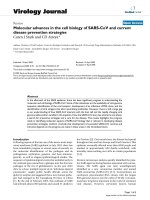
respectively. The influence of these stresses can be readily seen in a coupon
specimen as shown in Figure 2.1. Note that in a real repair, the restraint from the
Fig.
2.1.
Photograph
of
a 3mm thick
2024
aluminium specimen with a 0.6mm thick boron patch. The
curvature results
from
the
121
"C
cure temperature used to cure the
FM73
adhesive.
36
Advances in the bonded
composite repair
of
metallic aircraft
structure
substructure will minimise any actual bending, however, the residual stresses will
still be present. Often, if an elevated-temperature curing adhesive is used, residual
stresses will exist when the repair has cooled to ambient temperature. On the other
hand if an ambient-temperature curing adhesive is used with different repair
materials,
residual stresses can be induced if the repair has to operate at
temperatures significantly different from that at which the cured was achieved.
The level of stress is highest when the difference between the coefficients of thermal
expansion
(a)
are greatest. The use of a unidirectional gr/ep repair patch (which has
an
a
of
-0.3
OC-')
will
create a large residual stress when bonded to aluminium
(a
=
23.5
OC-').
If the repair material is different
to
the substrate, the level of residual stress
should be calculated during the design process. Procedures for analysing the
residual stress level are given in Chapter
1 1.
In extreme cases, the level of thermally
induced residual stress can be large enough to fail the joint, although this is not
usual. Residual stresses will influence the stress intensity at the defect site after
repair and possibly the static and fatigue strength of the repair and therefore it is
important that they be carefully considered during the repair design.
There are several ways in which the level of residual stress in an adhesive joint can
be minimised. Clearly choosing the repair material to be the same as the substrate is
the easiest, however, this may often not be the optimum choice. Usually the benefits
of using a fibre reinforced composite as the repair material outweigh the
disadvantage of increased residual stress levels. Secondly, it may be possible to
reduce the temperature of cure
so
as to keep the residual stress levels as low as
possible and the factors to consider in such a situation have been discussed in Section
2.3.3.
Thirdly, if the extent of the structure to be heated is minimised, this will act to
keep the residual stresses low. For example, when an aluminium skin of an aircraft is
heated, the skin
is
not able to expand in an unconstrained manner. The structure
surrounding the heated zone will be cooler, will not expand as much and will
therefore act as
a
constraint to the expansion of the repair zone. For this reason,
when it is important to minimise residual stresses, consideration can be given to
heating the smallest possible repair zone
so
as to maximise the constraint. Analytical
considerations for constrained expansion are discussed in Chapter 1
1.
Of course care
must
be
taken to ensure that the adhesive
is
uniformly heated and that the edges of
the repair are not under cured (Chapter
24).
Finally, it may
be
possible to apply a
pre-load to the structure to off-set the expected thermal expansion.
This
has been
done successfully during an important reinforcement to the
F-1
1
1
Wing Pivot
Fitting
[lo].
An
upload was applied to the wing, prior to the repair, placing the upper
wing skin in compression. Normally the metallic substrate is left in a state
of
tension
following the elevated temperature cure.
By
releasing the compressive pre-load after
the repair, the extent of the tensile residual stress was substantially reduced.
2.6.2.
Cure pressure
and
voids
Voids within the adhesive bondline are generated during the cure from either
entrapped air or from gases generated from the adhesive or adherends. The gas will
Chapter
2.
Materials selection and engineering
31
(a)
(b)
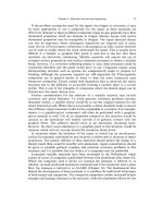
Fig.
2.2.
Micrographs showing fractured adhesive surfaces containing voids. The void concentration
seen in (b) resulted from the aluminium substrate being heavily grit blasted before application of the
silane solution. The only different process applied to (a)
was
a
drying period at 110°C in an oven after
the application of the silane.
typically form a bubble within the liquid adhesive and when the adhesive has cross-
linked and solidified, the bubble remains as a void as shown in Figure
2.2.
Gases
that are commonly involved in this process are water vapour present on the
adherends [13], water or other chemicals generated during the curing reaction, or
solvents such as MEK or acetone present within the adhesive that are liberated
during the cure. The gases themselves are not normally of any concern, however,
the voids that are created by the gases can act as stress concentration sites within
the adhesive. If the void concentration is sufficiently high, there could be a
reduction in the mechanical properties of the joint. In extreme cases the void
content can be more than
50%
of the joint area, and at these levels significant
reductions in strength can be expected.
A
preliminary study into the influence of
voids on fatigue strength indicated that for FM300 adhesive, a void content of
more than 30% was required before there was a noticeable drop in fatigue
performance.
A
possible reason for this was that the scrim cloth inside the adhesive
acts as a site for fatigue initiation and occupies approximately
30%
of the joint
area. It is not until the void content exceeds this level that there is a marked
reduction in fatigue life.
Void contents less than
5%
should be readily achievable in adhesive bondlines
during repair procedures. Keeping void contents low is a matter of recognising
the origins of the voids and ensuring that appropriate procedures are used. If the
38
Advances
in
the
bonded composite repair
of
metallic aircrafr structure
voids arise from adsorbed water vapour on the adherends, the bonding surfaces
should be dried prior to bonding
[13].
Entrapped air can
be
minimised by correct
procedures such as avoiding blending air into paste adhesives during mixing, and
avoiding applying film adhesives to adherends at too high a temperature where
they become too tacky. Voids generated from volatiles within the adhesive are
perhaps the most common reason for voids in film adhesives and can be
minimised in several ways. Before using the adhesive, it may be possible to
“B-
stage” the adhesive film by gently heating in an oven. This permits the volatiles to
be
released and partially cures the adhesive. This partial cross-linking prior to the
full cure helps to prevent the expansion of voids. Care needs to be taken during a
B-staging operation to ensure the adhesive is not advanced too far
so
that flow is
restricted. Pressure applied to the joint during the cure helps to restrict the
expansion of the volatile gases within the voids. In this regard the use of positive
pressure is much preferred to the use of a vacuum bag, as the negative pressure
within the bag can allow the expansion of the voids at some locations such as
around the edges or where the bag is unable to transmit the atmospheric pressure.
With either type of pressure application, it is difficult to generate the high
pressure desired in the interior
of
the joint if the joint is too narrow
[13].
Figure
2.2
illustrates the improvements in void contents that are possible by using
improved processes and with a fully optimised bond procedure, negligible void
contents should be readily achievable.
2.6.3.
Spew
jillet
For structurally loaded joints, it is well known
[I41
that the adhesive spew fillet
that forms around the edge
of
the joint is beneficial. This spew is formed as some
of
the adhesive flows out from under the repair patch during the cure and the resulting
fillet acts to soften the stress concentration at the edge of the repair patch. The
presence of the fillet can reduce the magnitude of the shear stresses at the end of the
joint by around
30%.
It
is
thus very important that this adhesive fillet is not
removed during the final clean up procedure.
The condition
of
the fillet can also be an important point to visually check after
the repair has been completed. Some information about the quality of the
adhesive bond can be gained by this visual inspection. The absence
of
a well
formed, smooth fillet would indicate poor flow
of
the adhesive and this may have
been due to inadequate pressurisation, out of life adhesive or perhaps the heat up
rate being too slow. An extremely high void content in the fillet could be an
indication
of
an excessively high volatile content within the adhesive or perhaps
the use of poor pressurisation procedures involving a vacuum bag. A large
amount
of
adhesive in the fillet may indicate that the bond has been subjected to
excessive pressure and that the bondline around the edge
of
the joint may be
starved of adhesive due to excessive flow. If the spew is not fully hardened, it
would indicate that the cure is not complete and either the required time or
temperature has not been reached.
Chapter
2.
Materials selection and engineering
39
2.6.4.
Composites offer the possibility
of
embedded strain
sensors
to form
“SMART”
repairs
There are a number of materials engineering advantages when a composite
material
is
used to form the repair patch rather than a metallic material. One of
these is that the patch can be readily formed to match the complex curvatures that
are often found on aircraft surfaces. Another is that by virtue of the way in which
composite materials are produced, it is comparatively easy to include small sensors
within the patch material. In the short term this
is
unlikely to be cost effective for
routine repairs as the additional costs involved will be high, however, this is
expected to change as the costs of sensors and associated instrumentation reduce.
For critical repairs to primary structure, these extra costs are less important and
repairs are being developed for such applications with inbuilt sensing mechanisms.
These patches will have the ability to detect strain transfer into the patch and
therefore will be able to determine if the patch is disbonding. When combined with
the ability to transfer the data collected by remote means (infra red or high
frequency communication for example), the “Smart” repair will be able to inform
the maintenance crew
if
there is any important structural problem. This topic is
covered in more detail in Chapter
20,
where some examples are given of the way in
which the technology can be used.
References
1. Baker, A.A. and Jones, R. (eds.) (1988). Bonded Repair of Aircraft Structures, Martinus Nijhoff
Publishers, Dordrecht.
2. Hart-Smith, L.J., Brown,
D.
and Wong,
S.
(1993). Surface Preparations for ensuring that the Glue
will stick in Bonded Composite Structures,
10th
DoD/NASA/FAA Conference on Fibrous
Composites in Structural Design, Hilton Head
Is,
SC.
3. Vlot, A., Vogelesang,
L.B.
and de Vries, T.J. (1999). Towards application of fibre metal laminates in
large aircraft.
Aircraft Engineering and Aerospace Technology,
71(6), pp. 558-570.
4. Fredell, R., van Barneveld,
W.
and Vogelesang, L.B. (1994). Design and testing of bonded GLARE
patches in the repair of fuselage fatigue cracks in large transport aircraft.
Proceedings
of
the 39th
International SAMPE Symposium,
1 1-14 April, pp. 624-638.
5.
Solly, R.K., Chester, R.J. and Baker, A.A. Bonded Repair of a Damaged Army Field Gun, Using
Electroformed Nickel Patches, in preparation.
6. Chester, R.J., Clark,
G.,
Hinton, B.R.W.,
et
al.
(1993). Research into materials aspects of aircraft
maintenance and life extension.
Aircraft Engineering,
Part
1,
65(1) pp. 2-5, Part
2,
65(2) pp.
2-5,
Part 3, 65(3), pp. 2-6.
7.
Fredell, R., van Barneveld,
W.
and Vlot, A. (1994). Analysis
of
composite crack patching
of
fuselage
structures: High patch elastic modulus isn’t the whole story.
Proceedings
of
the 39th International
SAMPE Symposium,
11-14 April, pp. 61M23.
8.
Bartholomeusz, R.A., Baker, A.A., Chester, R.J.,
et al.
(1999). Bonded joints with through thickness
adhesive stresses
-
reinforcing the F/A-18 Y470.5 Bulkhead.
Int.
J.
of
Adhesion and Adhesives,
19,
9. Chester, R.J., Chalkley, P.D. and Walker, K.F. (1999). Adhesively bonded repairs to primary
10. Baker, A.A., Chester, R.J., Davis, M.J.,
et al.
(1993). Reinforcement of the F-111 wing pivot fitting
pp. 173-180.
aircraft structure.
Int.
J.
of
Adhesion and Adhesives,
19,
pp.
1-8.
with a boron/epoxy doubler system
-
materials engineering aspects.
Composites,
24,
pp. 51 1-521.
40
Advances in the bonded composite repair of metallic aircraft structure
11.
Chalkley, P.D. and Geddes,
R.
(1999). Fatigue testing
of
bonded joints representative
of
the F-Ill
WPF
Upper Plate Doublers. DSTO
-
TR
-
0920, December.
12. Boeing System Support Standard
BSS
7240 Adhesive
Flow
Test.
13. Chester, R.J. and Roberts, J.D. (1989). Void minimisation in adhesive joints.
Int.
J.
ofAdhesion
and
14.
Adams, R.D. and Peppiatt,
N.A.
(1974). Stress analysis
of
adhesive-bonded lap joints.
J.
Strain
Adhesives,
9,
p. 129.
AnaIysis,
9,
pp. 185-196.
Chapter
3
SURFACE TREATMENT AND REPAIR BONDING
D.
ARNO'IT, A. RIDER and
J.
MAZZA*
Defence Science and Technology Organisation, Air Vehicles Division, Australia
*Materials and Manufacturing Directorate,
US.
Air Force Research Laboratory
(AFRLIMLSA)
,
Australia
3.1.
Introduction
Adhesion can be seen as the force or energy of attraction between two materials
or phases in contact with each other
[I].
In order to achieve intimate contact, one
phase called the adhesive must behave as a liquid at some stage and wet the second
phase called the adherend. It may be necessary to apply heat or pressure for the
adhesive to behave as a liquid. Once formed, the adhesive bond is expected to carry
loads throughout the life of the joint. Although many substances can act as an
adhesive, the discussion here is restricted to toughened epoxy adhesives used to
bond metallic aircraft structure. Discussion
of
adherends will also be restricted to
metals and composites.
This chapter focuses on prebonding surface treatments and bonding procedures
leading to the development of durable void-free adhesive bonds for repair
applications. It describes both fundamental aspects, including some current
research work, and practical procedures. A basic understanding is required to
avoid some of the many pitfalls that can lead to inadequate bonding. It is
complimentary to Chapter
24
which deals also with practical bonding.
There is no doubt that the reproducible development of durable bonds is a key
issue for bonded repair technology
[2].
3.1.1.
Surface energy and wetting
The complex interface between an adhesive and a metal adherend is best
described as an interphase in which critical dimensions are measured in
nanometres. Although there is controversy over the exact nature of the interactions
between epoxy polymers and metal oxides on the adherend
[3],
it is generally
believed that the predominant forces involve hydrogen bonds in which the hydroxyl
41
Baker,
A.A
Rose, L.R.F.
and
Jones, R. (e&.).
Advances
in
the
Bonded Composite Repairs
of
Metallic Aircraft Structure
Crown Copyright
0
2002
Published by
Elsevier
Science Ltd.
All
rights reserved.
42
Advances
in
the bonded composite repair
of
metallic aircraft structure
groups on the metal oxide interact with hydroxyl groups in the polymer
[4].
However, it is very likely that
a
variety of chemical bonds and interaction forces are
involved as well.
The interactions between an adhesive and an adherend are often described in
thermodynamic terms with expressions derived for the case of a liquid drop
adsorbed on a flat, homogeneous substrate in the presence of vapour
[5].
The
balance of forces between the liquid drop and the solid substrate in equilibrium
with vapour (Figure
3.1)
can be expressed in terms of the Young equation
[6]:
where
y
represents the relevant surface tensions at the three-phase contact point
(i.e. solid-vapour (sv), solid-liquid (sl) and liquid-vapour (Iv)) and
8
is the
equilibrium contact angle. Low values of
8
suggest strong attractive interfacial
forces between the liquid and the adherend or a tendency to wet the substrate and
to establish intimate atomic contact with the solid. Contaminant present on the
solid can lead to
a
weakening of the attractive forces with the liquid phase and
hence to a change in the contact angle.
The issues of wetting are complex, particularly in response to chemical
inhomogeneity
[6],
rough surfaces
[
1,7],
capillary forces
[SI
and the dynamic
spreading
of
viscous liquids
[SI.
Theoretical considerations indicate that external
pressure
to
assist the capillary driving pressure and heat (or solvent) to lower the
viscosity
of
the adhesive will aid wetting and penetration [9,10]. Adherend surface
preparation plays
a
pivotal role in the formation of a strong and durable adhesive
bond.
nV
Fig.
3.1.
Balance of surface
tensions
for
a
liquid drop on a
solid
surface.
3.
I.2.
Bondline pressurisation and adhesive cure
The structural film adhesives are cured thermally using controlled heating rates.
During heating, the adherends are pressurised either mechanically or hydro-
statically.
As
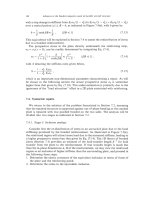
the temperature is ramped up, the viscosity
of
the adhesive initially
decreases, then it increases as the polymer crosslinks
[l
11.
In a pressurised sandwich
of
2
metal plates separated by a film adhesive, the adhesive
will
flow during the low
viscosity phase and the plate separation
will
decrease (Figure
3.2).
A
quadratic
pressure profile is developed within the adhesive [l
11.
The local pressure in the
adhesive at the centre of the sandwich is higher than the applied load
on
the plate
Chapter
3.
Surface treatment and repair bonding
43
10’
1
o8
lo7
I
5
IO6
k
3
io5
io4
In
1000
100
t
I
I
I
I I I
I
10 0.01
0
20 40
60
80
100 120 140
Temperature
(“C)
Fig.
3.2.
Pressurised sandwich panel showing viscosity changes with temperature and consequent
calculated plate separation for a typical thermoset epoxy film adhesive.
and can lead to deformation of thin adherend plates loaded by hydrostatic
pressure. The thickness of the bondline at the plate edges can be less than at the
centre for cures conducted using vacuum bag procedures. The pressure profile also
applies a hydrostatic constraint to bubble development in the adhesive and it is not
uncommon for voids to develop at the periphery of a repair when using a vacuum
bag for bond pressurisation. It must be kept in mind that almost all structural film
adhesives are designed for a positive pressure constraint on volatile gases to
minimise bubble development.
3.1.3.
Adhesive bond performance
A
strong adhesive bond does not imply a long-lasting or durable bond. Water is
the environment most commonly assessed in the literature, although other fluids
such as fuel and hydraulic fluid may degrade a bond. This chapter will focus on the
critical role of adherend surface treatment on the durability of a stressed adhesive
bond exposed to a humid atmosphere
[12].
Whilst much has been written on the subject of adhesive bonding, knowledge
is
still inadequate, and the engineering tools available for the through-life manage-
ment of adhesively bonded structure are primitive. The books by Kinloch
[13]
and
Minford
[
141 are, respectively, an excellent introduction to adhesion and adhesives
and a compendium for adhesion with aluminium alloys. It is not the intent of the
authors to reproduce a summary of these works here. The focus will be on surface
treatments for repair bonding, giving consideration to the atomic nature of the
bond interface and the relationship between microscopic behaviour and macro-
scopic mechanical properties. It cannot be over emphasised that a strong adhesive
44
Advances
in
the
bonded
composite repair
of
metallic aircraft structure
bond does not imply a durable bond. The influence of adherend surface treatment
on bond durability is therefore a key issue.
3.1.4. Standards and environments for adhesive bonding
The facilities, environment, conditions, skills and techniques available for
adhesive bonding vary widely. However, it must be emphasised that the quality and
long-term performance of an adhesive bond relies
on
attention to standards and the
skill of the technician, together with controls over processes and procedures for all
bonding situations.
3.1.4.1. Bond integrity and standards
Adhesively bonded components are manufactured, and bonded repairs are
conducted, without the benefit of a comprehensive set of effective nondestructive
process control tests or techniques to fully assess the through-life integrity of the
bonded product. Nondestructively inspected (NDI) techniques may be able to
detect physical defects leading to voids or airgaps in bondlines but they cannot
detect weak bonds or bonds that may potentially weaken in service. The quality
and integrity of the bonded component, thus, relies upon a fully qualified bonding
procedure, together with the assurance that the process was carried out correctly.
The Aloha Airlines Boeing
737
incident in April
1988,
where the aircraft lost part
of the cabin roof in an explosive decompression
[15,16],
illustrates the importance
of bond durability and more importantly, the ease with which this issue was
overlooked.
In the repair environment, experience has shown that some bonded repair
designs and application procedures have little chance of success and can, in some
cases, decrease the service lives of components
[17].
A survey of defect reports
conducted at one Royal Australian Air Force (RAAF) Unit
[17-191
indicated that
53%
of defects outside structural repair manual limits were related to adhesive
bond failure. In addressing the standards applied to adhesively bonded repairs, the
RAAF
[20]
have established a substantial improvement in the credibility of bonded
repair technology.
3.1.4.2. Adhesive bonding environments
The performance of an adhesive bond is sensitive to the adherend surface
treatment and the environmental conditions under which the bond is prepared.
Facilities located adjacent to operational airbases or in industrial environments need
to have concern for the effect of hydrocarbon contamination. Facilities in tropical
locations need special consideration for the effect of heat and high humidity.
Factory manufacture uses specialised facilities and staff. The facilities will
include vapour degreasing or alkaline cleaning, etching tanks, anodising tanks, jigs,
autoclaves and appropriate environmental controls. Adhesives will be stored in
freezers, and monitoring procedures will be in place. There is a well trained
workforce with skills maintained through production volumes, and highly
developed inspection procedures are available.
Chapter
3.
Surface treatment
and
repair
bonding
45
At the other extreme, field repairs are generally conducted with relatively
unsophisticated facilities, minimal surface treatments, vacuum bag or reacted force
pressurisation and little or no environmental control. Staff multiskilling and
rotation influence the currency of experience and hence the quality and
performance of adhesive bonds
[21].
The requirement for environmental controls,
the attention to bonding procedure detail and the need for staff training and
supervision is of particular concern.
Depot-level repairs are conducted with facilities and staff skills that vary
considerably. Some depots have almost factory-level facilities and high level of staff
skill. Other depots are capable of only low-level bonded repairs and are little
removed from a field repair capability.
Laboratory experiments are designed to establish knowledge and principles. It is
easy to overlook important detail from factory or field experience since most
laboratories are held to close environmental tolerances and do not resemble the
workshop environment.
3.1.4.3.
Constraints for on-uircruft
repairs
On-aircraft repairs impose additional constraints on processes and procedures.
The considerations include: accessibility of the area, limitations in the use of
corrosive chemicals, adequacy of environmental controls and constraints on the
tools for pressurisation and heating of the bond during cure. Safety, health and
environmental issues are more demanding for on-aircraft bonding since it is harder
to control, contain and clean-up hazardous chemicals. Constraints on the use of
electrical power on fuelled aircraft, or those with inadequately purged fuel tanks,
can restrict the range of treatment and bonding methods available. The
surrounding aircraft structure imposes constraints on the choice of surface
preparation, heating arrangements and pressurisation tools.
3.2.
Mechanical
tests
3.2.1.
Loading and failure modes
The most common method used to assess the relative performance of an
adherend surface pretreatment involves loading an adhesive joint asymmetrically in
tension, as shown in Figure
3.3,
described as mode
I
opening. The stresses leading
to failure are localised in a region adjacent to the crack tip. The extent of this region
depends on the stiffness of the adherends, the toughness of the adhesive and,
importantly, the effectiveness
of
the adherend surface treatment.
The mechanical performance of a bond should be accompanied by an inspection
of the fracture surface. Visual inspection assisted with optical microscopy will
provide macroscopic information concerning the locus
of
fracture and the presence
of voids or defects. The term cohesional failure describes fracture totally within the
adhesive, leaving adhesive on both separated adherends. The term adhesional
failure describes a fracture at one interface with the adherend, resulting in one face
46
Advances in the
bonded
composite repair
of
metallic aircraft structure
Fig.
3.3.
Asymmetric tension
or
mode
I
opening
of
an adhesive joint.
having the visual appearance of the adherend material and the mating face with the
appearance of the adhesive. Visual inspection alone does not convey the complete
picture. Because an adhesive bond
is
formed as a result of atomic interactions,
closer inspection of adhesional failures with surface composition analysis
techniques can provide detailed insight into the material leading to the weakness
at the fracture site.
3.2.2.
Qualification
of
bonding procedures and performance
An adhesive bond represents a complex system of materials, treatments and
processing steps. The issue of qualification of the adhesive system is complex since
specific requirements depend on the application. The focus must be on mechanical
performance and durability because the bonded joint
is
expected to transfer load
for the service life. For structural joints, strength
is
typically evaluated using shear
tests (for static properties and fatigue) and toughness with cleavage tests. For
honeycomb structure, properties are typically evaluated with flatwise tension and
peel tests. Tests are conducted at representative temperatures experienced
throughout the service environment, including the operating extremes. Tests are
also conducted using moisture-conditioned specimens to evaluate durability
performance. Other conditioning may include exposure to salt fog,
SO2,
hydraulic
fluids, fuels, de-icers and more. Subcomponent or component testing normally
follows coupon testing.
The failure modes of test specimens are as important as the strength or toughness
values obtained. Failure modes at interfaces between the treated metal surface and
the adhesive or primer are generally not acceptable. The primary objective is for the
mechanical properties of joint to be limited
by
the properties of the cured adhesive,
not the surface treatment.
Qualification of the adherend surface treatment procedure
is
of particular
importance. Many surface preparations can provide adequate initial bond strength,
however, maintaining this strength for the life of a system in its operating
environment is a more difficult challenge. Moisture durability is of primary
concern. However, for certain titanium applications, long-term durability at
elevated temperature is important.
Chapter
3.
Surfnee treatment
and
repair
bonding
3.3.
Standard
tests
41
3.3.1.
Wedge durability test
The ASTM
D
3762 wedge test is often called the Boeing wedge durability test.
A
crack is initiated in a bonded joint through insertion of a wedge into the
bondline (Figure 3.3). The test specimen is then exposed to hot/wet conditioning
and crack growth is monitored. The initial pre-exposure fracture is expected be
cohesive within the adhesive layer, and the equilibrium crack length is therefore
expected to reflect the toughness of the adhesive system under dry conditions. An
excessive initial crack length accompanied by interfacial failure, even before
environmental exposure, reflects a poor surface treatment. The specimen failure
mode is a critical piece of information. Cracks that remain within the adhesive
are desirable since they indicate that the surface preparation is not the weak link
in the bonded joint. Poor surface preparations readily lead to interfacial failures
accompanied by substantial crack growth. The wedge test
is
properly employed to
compare a surface preparation against a control, provided all aspects of specimen
configuration and conditioning are held constant as the surface treatment
is
varied.
The wedge test is widely misused because ASTM D 3762 is not fully prescriptive.
Difficulties in the comparison of published data occur because pass/fail criteria,
conditioning environment, time of conditioning, and limits on adhesive systems are
not fully specified.
By
way of illustration, the
US
Services mostly condition wedge
specimens at 60 "C and
95%
relative humidity
(RH),
whereas the Australian
counterpart test in condensing humidity at
50
"C. As a second illustration, the high
fracture energy characteristics of tough adhesives place higher demands on the
performance of the surface treatment than do brittle adhesives. The testing of tough
adhesives introduces the essential requirement to conduct a simple calculation to
ensure that the adherends will not plastically deform in cases where fracture energy
measurements are made
[22].
However, bonded joints that strain significantly when
exposed to hot/wet environment may provide a less rigorous test and, generally, the
wedge test is not used to provide quantitative data.
The wedge test is a severe test, since the adhesive is at its breaking stress at the
crack tip while directly exposed to the conditioning environment. For this reason,
surface preparations that allow limited interfacial failures may be satisfactory. The
RAAF
Engineering Standard C5033 [20] uses crack growth criteria and allows
some interfacial failure in relation to one particular tough adhesive based on service
histories of
RAAF
aircraft. However as a general rule, without service experience
to correlate with test results, the safe approach is to insist on a cohesional failure
mode, where the adhesive, rather than the surface treatment, limits the mechanical
properties of the adhesive bond.
There is ongoing pressure to establish a relationship between service life and the
performance of an accelerated durability test. Although the wedge test has been
correlated to adhesive bond service life for limited applications, similar durability
performance for new treatments does not imply similar service lives [23]. With