Advances in the Bonded Composite Repair o f Metallic Aircraft Structure phần 3 pptx
Bạn đang xem bản rút gọn của tài liệu. Xem và tải ngay bản đầy đủ của tài liệu tại đây (1.54 MB, 62 trang )
82
Advances in the bonded composite repair of metallic aircraft structure
the durability
of
this treatment may perform as well as phosphoric acid anodisation
for some aluminium alloy and epoxy adhesive combinations [127].
Fundamental research has identified that optimum durability is achieved for
immersion
of
the aluminium between 4min and
1
h in the distilled water heated to
between
80
"C
and 100
"C.
These conditions enable a platelet structure to grow in
the outer film region, which, combined with the formation
of
hydrolytically stable
adhesive bonds made to the epoxy silane, appears to be critical in the development
of the excellent bond durability [127].
References
1. Huntsberger, J.R. (1981). Interfacial energies, contact angles and adhesion. In,
Treatise on Adhesion
2. Baker, A.A. (1999). Bonded composite repair of primary aircraft structure,
Composite Structures
3. Kinloch, A.J. (1986). Adhesion and Adhesives, Science and Technology. Chapman
&
Hall, London
4. DeBruyne, N.A. (1956).
J.
Appl. Chem,
6,
July, p. 303.
5.
Huntsberger, J.R. (1981).
J.
Adhesion,
12, pp. 3-12.
6. Hiemenz, P.C. (1986). Principles of Colloid and Surface Chemistry, revised and expanded, (2nd
7. Wenzel, R.N. (1936).
Ind. Eng. Chem.,
28, p. 988.
8. Bascom, W.D. and Partick, R.L. (1974).
Adhesives Age,
17(10), p. 25.
9. DeBruyne, N.A. (1956). Aero Research Tech Notes No 168, p. 1.
and Adhesives,
(R.L. Patrick, ed.), Marcel Dekker Inc.,
NY,
5,
p.
1.
47, pp. 431443.
&
New York, pp. 5657.
ed.), Marcel Dekker, Chapter 6.
10. Packham, D.E. (1983). In Adhesion Aspects of Polymeric Coatings (K. Mittal, ed.) Plenum N.Y.,
p. 19.
11. Arnott, D.R., Wilson, A.R., Pearce, P.J.,
et al.
(1997). Void development in aerospace film
adhesives during vacuum bag cure.
Int. Aerospace Congress
97,
Sydney Australia, 2&27 February,
p. 15.
12. Arnott, D.R., Wilson, A.R., Rider, A.N.,
et al.
(1993).
Appl. Surf Sci,
70/71, p. 109.
13. Kinloch, A.J. (1987). Adhesion and Adhesives
-
Science and Technology, Chapman and Hall.
14. Minford, J.D. (1993). Handbook of Aluminium Bonding Technology and Data, Marcel Dekker.
15. Macarthur Job Air Disaster Volume 2 Aerospace Publications PO Box 3105 Weston Creek ACT,
(1996) Chapter
11.
16. Davis, M.J. (1997). Deficiencies in regulations for certification and continuing airworthiness of
bonded structures.
Int. Aerospace Congress
97,
24-21 February, Sydney, Australia, IEAust. p. 21 5.
17. Davis, M.J. (1996).
Pro. 41st ht. SAMPE Symp.
March, p. 936.
18. Davis, M.J. (1995).
Pro. Int. Symp. on Composite Repair of Aircraft Structure,
Vancouver, 9-11
August.
19. Hart-Smith, L.J. and Davis, M.J. (1996).
Pro. of 41st Int. SAMPE Symp. and Exhibition,
Anaheim,
25-28 March.
20. Royal Australian Air Force Engineering Standard (25033, Composite Materials and Adhesive
Bonded Repairs, September 1995, RAAF Headquarters Logistics Command, Melbourne, Vic.,
Australia.
21. Pearce, P.J., Camilleri, A., Olsson-Jacques, C.L.,
et al.
(1999). A Benchmarking Review of RAAF
Structural Adhesive Bond Procedures, DSTO-Aeronautical and Maritime Research Laboratory
Report DSTO-TR-0267. May.
22. Gurney, G. and Amling, R. (1969). Adhesion Fundamentals and Practice, McLaren, pp. 21 1-217.
23. Baker, A.A. (1988). In Bonded Repair of Aircraft Structures, (A.A. Baker, and R. Jones, eds.)
Martinius Nijhoff, Dortrecht, p. 118.
Chapter 3.
Surface treatment and repair bonding
83
24. Ashcroft, LA., Digby, R. and Shaw, S.J. (1998). Accelerated Ageing and life prediction of
Adhesively-bonded Joints, Abstracts Euradhesion 98/WCARP
1,
Garmisch Partenkirchen
Germany,
6-1
1
September, p. 285.
25. Hardwick, D.A., Ahearn, J.S. and Venables, J.D. (1984).
J.
Mat. Sei.,
19, p. 223.
26. Cognard, J. (1986).
J.
Adhesion,
20, p. 1.
27. Broek, D. (1986). Elementary Engineering Fracture Mechanics, Martinius Nijhoff, p. 128.
28. Stone, M.H. and Peet, T. (1980). Evaluation
of
the Wedge Test For Assessment of Durability of
Adhesive Bonded Joints Royal Aircraft Establishment Tech. Memo, Mat 349, July.
29. Mostovoy,
S.,
Crosley, P.B. and Ripling, E.J. (1967).
J.
of Materials,
2(3), p. 661.
30. Grosko, J., Lockheed Aeronautical systems Co, Georgia Division (communication).
31. Kinloch, A.J. (1987). Adhesion and Adhesives Science and Technology, Chapman and Hall,
London, pp. 123-151.
32. Rider, A.N. and Arnott, D.R. (2000). The influence of adherend topography on the fracture
toughness of aluminium-epoxy adhesive joints in humid environments, (2001)
J.
of Adhesion
33. Rider, A.N. and Arnott, D.R. (1998). Influence
of
Adherend Topography on the Durability of
Adhesive Bonds Structural Integrity and Fracture (Wang, Chun H., ed.) 21-22 Sept., Melbourne
Australia (ISBN (Book)
0
646 36038 8), pp. 121-132.
34. Rider, A.N. (1998). Surface Properties Influencing the Fracture Toughness of Aluminium Epoxy
Joints Ph.D. University of New South Wales, Australia.
35. Schmidt, R.G. and Bell, J.P. (1986).
Advances in Polymer Science,
19, p. 41.
36. Arnott, D.R., Rider, A.N., Olsson-Jacques, C.L.,
et a/.
(1998). Bond durability performance
-
The
37. Hong, S.G. and Boerio, F.J. (1990).
J.
Adh.,
32, p. 67.
38. Olsson-Jacques, C.L., Wilson, A.R., Rider, A.N.,
et al.
(1996). The Effect of Contaminant on the
Durability
of
Bonds Formed with Epoxy Adhesive Bonds with Alclad Aluminium Alloy,
Surface
and Interface Analysis,
24(9), pp. 569-577.
39. Arnott, D.R., Wilson, A.R., Rider, A.N.,
et al.
(1997). Research underpinning the adherend surface
preparation aspects
of
the RAAF engineering standard C5033,
Int. Aerospace Congress
97,
Sydney,
Australia, 24-27 February, p. 41.
75, pp. 203-228.
Australian Silane Surface Treatment,
21st Congress of ICAS,
13-18 Sept, Melbourne, Australia.
40. Venables, J.D. (1984).
J.
Mater. Sci.
19, p. 2431.
41. Rider, A.N., Arnott, D.R., Wilson, A.R.,
et al.
(1995). Materials Science Forum, pp. 189-190,235-
42. Rider, A.N. and Arnott, D.R. (1996). Surface and Interface Analysis, 24(9), p. 583.
43. Arnott, D.R. and Kindermann, M.R. (1995).
J.
of
Adhesion,
48, pp. 101-119.
44. Cognard, J. (1996).
J.
Adhes.,
57,
p. 31.
45. Evans, J.R. and Packham, D.E. (1979).
J.
Adhesion,
10, p. 177.
46. Packham, D.E. (1986).
Int
J.
Adhesion
&
Adhesives,
2(4), p. 225.
47. Wilson, A.R., Farr, N.G., Arnott, D.R.,
et a/.
(1989). Relationship of Surface Preparation of Clad
2024 AluminiumAlloy to Morphology and Adhesive Bond Strength,
Australian Aeronautical Conf.,
Melbourne 9-1 1 Oct., pp. 221-225.
48. Lambrianidis, L.T., Arnott, D.R., Wilson, A.R.,
et al.
(1995). The Effect and Evaluation
of
Grit-
blast Severity on Adhesive Bond Durability for Aircraft Repairs.
2nd Pacific and Int. Conf.
on
Aerospace Science and Technology and 6th Australian Aeronautical Conf.,
2C23 March, Melbourne,
Australia, pp. 355-360.
49. Arnott, D.R., Pearce, P.J., Wilson, A.R.,
et al.
(1995). The effect on mechanical properties of void
formation during vacuum bag processing of epoxy film adhesives.
Proc. 2nd Paczjic and Int. Con$
on
Aerospace Science and Technology,
The Australian Institute of Engineers, Melbourne 21-23
March, pp. 811-816.
240.
50. Pearce, P.J., Arnott, D.R., Camilleri, A.,
et al.
(1998).
J.
Adh. Sci Technol.
12(6), p. 567.
51. Arnott, D.R., Baxter, W.J. and Rouze, S.R. (1981).
J.
Electrochem SOC.
(Solid State Science and
52. Venables, J.D. (1984).
J.
Mat. Sci.
19, pp. 2431-2453.
Technology), 128(4), pp. 843-847.
84
Advances
in
the bonded composite repair
of
metallic aircrafi structure
53. Solly, R.K., Chester, R.J. and Baker, A.A.
(2000).
Bonded Repair with Nickel Electroforms,
DSTO Technical Report, in preparation.
54. Clearfield, H.M., McNamara, D.K. and Davis, G.D. (1990). Engineered Materials Handbook,
Vol.
3 Adhesives and Sealants, H.F. Brinson (technical chairman), ASM International,
p.
259.
55.
Landrock, A.H. (1985). Adhesives Technology Handbook, Noyes Publications, Park Ridge, NJ,
p.
66.
56. Marceau, J.A. (1985). Adhesive Bonding of Aluminum Alloys, (E.W. Thrall and R.W. Shannon,
eds.) Marcel Dekker, Inc., New York,
51,
p.
51.
57. Young,
L.
(1961). Anodic Oxide Films, Academic Press, pp. 1-3.
58. Schmidt, R.C. and Bell, J.P. (1986). Advances in Polymer Science,
15,
p.
33.
59. Davis, G.D., Ahearn, J.S., Matienzo, L.J.,
et a!.
(1985).
J.
Mat. Sci.,
20,
p.
975.
60. Kuhbander, R.J. and Mazza, J.P. (1993).
Proc. 38th
Int.
SAMPE Symp.,
May 1&13,
p.
1225.
61. Baker, A.A. and Chester, R.J. (1992).
Int.
J.
Adhesion and Adhesives,
12,
p. 73.
62. Mazza, J.J., Avram, J.B. and Kuhbander, R.J. Grit-blast/Silane (GBS) Aluminium Surface
Preparation for Structural Adhesive Bonding, WL-TR-94-4111 (interim report under
US
Air Force
Contracts F33615-89-C-5643 and F33615-95-D-5617).
63. Clearfield, H.M., McNamara, D.K. and Davis,
G.D.
(1990). Engineered Materials Handbook,
Vol.
3 Adhesives and Sealants, H.F. Brinson (technical chairman), ASM International, p. 254.
64. Dukes, W.A. and Brient, R.W. (1969).
J.
Adhesion
I,
p. 48.
65. Wolfe, H.F., Rupert, C.L. and Schwartz, H.S. (1981). AFWAL-TR-81-3096 August.
66. Internal communication, Royal Australian Air Force, Amberley Air Force Base.
67. Wilson,
A.R.,
Kindermann, M.R. and Arnott, D.R. (1995). Void development in an epoxy film
adhesive during vaccum bag cure,
Proc.
2nd
Pacific and Int.
Con$
on
Aerospace Science and
Technology,
The Institution of Engineers, Australia, Melbourne, 2&23 March,
pp.
62S630.
68. Bijlmer, P.F.A. (1979). Characterisation of the Surface Quality by Means of Surface potential
Difference in Surface Contamination, Genesis Detection and Control,
2,
(K.L. Mittal, ed.) Plenum
Press, p. 723.
69. Smith,
T.
(1975).
J.
Appl. Phys.,
46,
p. 1553.
70. Gause, R. (1987).
A
non
Contacting Scanning Photoelectron Emission Technique for Bonding Surface
Cleanliness Inspection Fijth Annual NASA NDE Workshop,
Cocoa Beach, Florida,
Dec.
1-3.
71. Photo Emission Technology, 766 Lakefield Rd. Suite
h,
Westlake Ca 91361.
72. CRC Handbook of Chemistry and Physics, 54th edn. (1973/74) (R.C. Weast, ed.) Chemical Rubber
Co, p. E80.
73. Olsson-Jacques, C.L., Arnott, D.R., Lambrianidis, L.T.,
et al.
(1997). Toward quality monitoring
of adherend surfaces prior to adhesive bonding in aircraft repairs.
The Int. Aerospace Congress
1997
~
7th Australian Aeronautical
Con$,
24-27 February, Sydney, Australia, pp. 51 1-520.
74. Foster Miller Inc 195 Bearhill Rd. Waltham MA 02451-1003 and
75.
Minford, J.D. (1993). Handbook of Aluminium Bonding Technology and Data, Marcel Dekker,
p.
58.
76. Clearfield, H.M., McNamara, D.K. and Davis, G.D. (1990). Engineered Materials Handbook,
Vol.
3 Adhesives and Sealants, Brinson, H.F. (technical chairman), ASM International, p. 261.
77.
Kinloch, A.J. (1987). Adhesion and Adhesives Science and Technology. Chapman and Hall,
London, pp. 101-103.
78. Thrall, E.W. (1979). Failures in Adhesively Bonded Structures (Lecture No.
5),
Douglas Paper
6703, Presented to AGARD-NATO Lecture Series 102: Bonded Joints and Preparation for
Bonding,
Oslo
Norway and The Hague, Netherlands, April 2-3.
79. Shannon, R.W.,
et al.
(1978). Primary Adhesively Bonded Structure Technology (PABST) General
Material Property Data, AFFDL-TR-77-107 (report
for
US
Air Force Contract F33615-75-C-
3016), September.
80. Reinhart, T.J. (1988). Bonded Repair of Aircraft Strucures, (A.A. Baker and R. Jones, eds.),
Martinus Nijhoff Publishers, Dordrecht, The Netherlands,
23.
81. Clearfield, H.M., McNamara, D.K. and Davis, G.D. (1990). Engineered Materials Handbook,
Vol.
3 Adhesives and Sealants, Brinson, H.F. (technical chairman), ASM International, p. 260.
Chapter 3.
Surface treatment and repair bonding
85
82. ASTM D 3933-93, Standard guide for preparation of aluminum surfaces for structural adhesives
bonding (phosphoric acid anodising), 1997 Annual Book of ASTM Standards,
15.06,
American
Society for Testing and Materials, West Condshohocken, PA, (1997), pp. 287-290.
83. Griffen, C. and Askins, D.R. (1988). Non-Chromate Surface Preparation of Aluminum, AFWAL-
TR-88-4135 (interim report for
US
Air Force Contract
No.
F33615-84-C-5130), August.
84. Marceau, J.A. (1985). Adhesive Bonding of Aluminum Alloys, (E.W. Thrall and R.W. Shannon,
eds.), Marcel Dekker, Inc., New York, p. 55.
85. Askins, D.R. and Byrge, D.R. (1986). Evaluation of 350°F Curing Adhesive Systems on
Phosphoric Acid Anodised Aluminum Substrates, AFWAL-TR-86-4039 (interim report for
US
Air
Force Contract Nos. F33615-82-C-5039 and F33615-84-C-5130), August.
86. Peterson, E.E., Arnold, D.B. and Locke, M.C. (1981). Compatibility of 350°F curing honeycomb
adhesives with phosphoric acid anodising.
Proc.
of
13th National SAMPE Technical
Con$,
87. Kuperman, M.H. and Horton, R.E. (1985). Adhesive Bonding of Aluminum Alloys, (E.W. Thrall
88. Bijlmer, P.F. (1985). Adhesive Bonding of Aluminum Alloys, (E.W. Thrall and R.W. Shannon,
89. Rogers,
N.L.
(1985). Adhesive Bonding of Aluminum Alloys, (E.W. Thrall and R.W. Shannon,
90. Rogers, N.L., (1977).
J.
of
Applied Polymer Science: Applied Polymer Symp.,
32,
pp. 37-50.
91. Thrall, E.W. Jr., (1979). Failures in Adhesively-bonded Structures, Douglas Aircraft Company
Paper 6703, pp. 2-3.
92. Gaskin, G.B.,
et a/.
(1994). Investigation
of
sulfuric-boric acid anodizing as a replacement for
chromic acid anodization: Phase I.
Proc. 26th
Int.
SAMPE Technical
Conf.,
Atlanta GA, October,
93. Clearfield, H.M., McNamara, D.K. and Davis, G.D. (1990). Engineered Materials Handbook,
Vol.
3 Adhesives and Sealants, Brinson, H.F. (technical chairman), ASM International, pp. 260-
263.
94. Packham, D.E. (1992). Handbook of Adhesion, (D.E. Packham, ed.), Longman Scientific
&
Technical,
UK,
p. 201.
95. Adelson, K.M., Garnis, E.A. and Wegman, R.F. (1982). Evaluation of the Sulfuric Acid-Ferric
Sulfate and Phosphoric Acid Anodise Treatments prior
to
Adhesive Bonding of Aluminum,
ARSCD-TR-82013
(US
Army Final Report), September.
96. Pinnell, W.B. (1999). Hydrogen Embrittlement of Metal Fasteners Due to PACS Exposure, AFRL-
ML-WP-TR-2000-4153, (Report for Delivery Order 0004, Task 2 of
US
Air Force Contract
97. Locke, M.C. and Scardino, W.M. Phosphoric Acid Non-Tank Anodise (PANTA) Process for
98. Pergan,
I.
(1999).
Int.
J.
Adhesion
and
Adhesives,
19,
p. 199.
99. Saliba,
S.S.
(1993). Phosphoric acid containment system (PACS) evaluation for on-aircraft
pp. 177-188.
and R.W. Shannon, eds.), Marcel Dekker, Inc., New York, pp. 43W6.
eds.), Marcel Dekker, Inc., New York, pp. 28-32.
eds.),
Marcel Dekker, Inc., New York, pp. 41-49.
pp. 258-264.
F33615-95- D-5616), August.
Repair Bonding,
Proc.
of.
pp. 21 8-241.
anodisation of aluminum surfaces.
Proc.
of
38th Int. SAMPE Symp.,
38,
pp. 1211-1224.
100. Podoba, E.A., McNamara, D.,
et
al.
(1981).
Appl. Surf.
Sci.
9,
pp. 359-376.
101. Kuperman, M.H. and Horton, R.E. (1985). Adhesive Bonding of Aluminum Alloys, (E.W. Thrall
and R.W. Shannon, eds.), Marcel Dekker, Inc., New York, pp. 430446.
102. Locke, M.C., Horton, R.E. and McCarty, J.E. (1978). Anodize Optimization and Adhesive
Evaluations for Repair Applications, AFML-TR-78- 104 (final report for
US
Air Force Contract
103. Shaffer, D.K., Clearfield, H.M. and Ahearn, J.S. (1991). Treatise on Adhesion and Adhesives,
7,
104. Clearfield, H.M.,
et at.
(1989).
J.
Adhesion,
29,
pp. 81-102.
105. Brown, S.R. and Pilla, G.J. (1982). Titanium Surface Treatments for Adhesive Bonding, NADC-
106. Semco Pasa-Jell 107 Technical Data Sheet, February 1996.
F33615-73-C-5 17
l),
July.
(J.D. Minford, ed.), Marcel Dekker, Inc., New York, pp. 437-444.
82032-60 (phase report for
US
Navy Airtask No. WF61-542-001), March.
86
107.
TURCO@'
5578
Technical Data Bulletin, February
1999.
108.
Clearfield, H.M., McNamara, D.K. and Davis, G.D.
(1990).
Engineered Materials Handbook,
Vol.
3
Adhesives and Sealants, Bnnson, H.F. (technical chairman), ASM International, pp.
264-
273.
109.
Snogren, R.C.
(1974).
Handbook of Surface Preparation, Palmerton Publishing Co., Inc., New
York, p.
265.
110.
Landrock, A.H.
(1985).
Adhesives Technology Handbook, Noyes Publications, Park Ridge, NJ,
11
1.
Wegman,
R.F.
(1989).
Surface Preparation Techniques for Adhesive Bonding, Noyes Publications,
112.
Baker, A.A., Chester, R.J., Davis, M.J.,
et al.
(1993).
Composites,
24,
p.
6.
113.
Hart-Smith, L.J., Brown, D. and Wong,
S.
(1998).
Handbook of Composites, (S.T. Peters, ed.).
Chapman and Hall, London, pp.
667-685.
114.
Landrock, A.H.
(1985).
Adhesives Technology Handbook, Noyes Publications, Park Ridge, NJ,
pp.
105-106.
115.
Hart-Smith, L.J., Ochsner,
R.W.
and Radecky, R.L.
(1990).
Engineered Materials Handbook,
Vol.
3
Adhesives and Sealants, Brinson, H.F. (technical chairman), ASM International, pp.
840-
844.
116.
Hart-Smith, L.J., Redmond, G. and Davis, M.J.
(1996).
The curse of the nylon peel ply.
Proc. of
4Ist Int. SAMPE Symp.,
41,
pp.
303-317.
117.
Mazza, J.J.
(1997).
Advanced Surface Preparation for Metal Alloys, AGARD Report
816,
February, pp.
10-1
to
10-12.
118.
Blohowiak,
K.Y.
(2000).
Sol-gel technology for space applications.
Proc. National Space and
Missile Materials Symp.,
San Diego CA,
27
February-;! March.
119.
Baes, C.F. and Mesmar, R.E.
(1990).
In
Sol-Gel
ScienceThe Physics and Chemistry of Sol-Gel
Processing,
(C.J.
Brinker and
G.W.
Scherer,
eds.),
Academic Press, San Diego.
120.
Tiano, T., Pan,
M.,
Dorogy, W.,
et al.
(1996).
Functionally Gradient
Sol-Gel
Coatings for Aircraft
Aluminum Alloys,
WL-TR-96-4108
(final report
for
US
Air Force Contract
F33615-95-C-5621),
October.
121.
Chu, C. and Zheng, H.
(1997).
Sol-Gel Deposition of Active Alumina Coatings on Aluminum
Alloys,
WL-TR-97-4114
(final report for
US
Air Force Contract
F33615-94-C-5605),
August.
122.
Blohowiak, K.Y., Osborne, J.H. and Krienke, K.A.
US
Patents
6,037,060 (2000), 5,958,578 (1999),
5,939197 (1999), 5,869,141 (1999), 5,869,140 (1999), 5,849,110 (1998), 5,814,137 (1998).
123.
Ma=, J., Gaskin, G., DePiero, W.,
et al.
(2000).
Faster durable bonded repairs using sol-gel
surface treatment.
Proc. the 4th Joint DoDIFAAINASA
Con$
on
Aging Aircraft,
St. Louis MO,
May.
124.
McCray, D.B. and Mazza, J.J.
(2000).
Optimization of sol-gel surface preparations
for
repair
bonding
of
aluminum alloys.
Proc. 45th
Int.
SAMPE Symp. and Exhibition,
Long Beach CA, May,
pp.
53-54.
125.
Blohowiak,
K.Y.,
Osborne, J.H., Krienke, K.A.,
et
al.
(1997).
DODIFAAINASA
Conf. on
Aging
Aircraft Proc.,
July
8-10,
Ogden
UT.
126.
McCray, D.B.,
et af.
(2001).
An ambient-temperature adhesive bonded
repair
process for aluminum
alloys.
Proc. 46th In?. SAMPE Symp. and Exhibition,
Long Beach CA, May, pp.
1135-1 147.
127.
Rider, A.N. and Arnott, D.R.
(2000).
Int.
J.
Adhes. and Adhes.,
20,
p.
209.
Advances in the bonded composite repair of metallic aircraft structure
pp.
72-75.
Park Ridge, NJ, pp.
6670.
Chapter
4
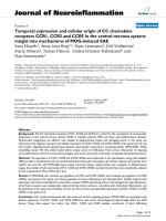
ADHESIVES CHARACTERISATION AND DATABASE
P.
CHALKLEY
and
A.A.
BAKER
Defence Science and Technology Organisation, Air Vehicles Division, Fishermans
Bend, Victoria
3207,
Australia
4.1.
Introduction
The design of a bonded repair is often more demanding than the
ab initio
design
of a bonded structure. For example, secondary bending in the repair, often induced
by the repair patch itself, can lead to the development of detrimental peel stresses in
the adhesive. Such stresses can
be
avoided or at least minimised in the early design
stages
of
a bonded panel
so
that the adhesive is mainly loaded in shear. For bonded
repair then, assuming the adhesive determines patch performance, a greater range
of allowables data is needed for the adhesive from pure shear through shear/peel
combinations to pure peel.
However, while the stress-strain properties
of
the adhesive largely determine the
efficiency
of
load transfer into the patch, there are several possible modes of failure
of the bond system, including:
0
The adhesive
0
The adhesive to metal or composite interface
0
The adhesive to primer interface
0
The surface matrix resin of the composite
0
The near-surface plies of the composite.
Obviously the failure mode that occurs will be the one requiring the lowest driving
force under the applied loading. Where more than two or more modes have similar
driving forces then mixed mode failure will result.
In this chapter it is assumed that the primary failure mode is cohesive failure of
the adhesive layer. This is a reasonable assumption for static loading for well-
bonded metallic adherends,
in
this case with a metallic patch. However, for
composites, such as boronlepoxy or graphitelepoxy, failure at low and ambient
temperature is often in the surface resin layer
of
the composite. The tendency for
87
Baker,
A.A.,
Rose,
L.R.F.
and Jones,
R.
(eds.),
Advances
in
the Bonded Composite Repairs
of
Metallic Aircraft Structure
Crown
Copyright
0
2002
Published by Elsevier Science
Ltd.
All
rights reserved.
88
Advances
in
the bonded composite repair of metallic aircraft structure
this mode of failure to occur will increase with low adhesive thickness, the presence
of peel stresses, low temperatures and under cyclic loading [l].
At high temperature and particularly under hot/wet conditions, the mode may be
expected to change to one of cohesive failure in the adhesive, even with composite
adherends since the matrix of the one of composite is generally more temperature
resistant than the adhesive.
Thus the test methods outlined here to determine the static properties of the
adhesive should provide useable design allowables for static strength
of
representative repair joints with metallic patches and in some circumstances with
composite patches. The methods are also required for determining the stressstrain
properties of the adhesive and thus the reinforcing efficiency of the patch prior to
failure.
Stress-strain and fracture mechanics type allowables are considered. Having
identified which design allowables are needed, typical manufacturers’ data,
including results from the more common ASTM tests, are examined for their
suitability (or lack
of)
for providing useful design allowables. Such data is often
found wanting and more suitable test methods for obtaining allowables are
suggested. Finally, a data set of some design allowables for one of the more
commonly used repair adhesives is tabulated.
The best approach for fatigue and other complex loading conditions is to obtain
the design allowables from representative joints, as discussed in Chapter 5.
4.2.
Common
ASTM
and
MIL
tests
Manufacturers’ data sheets often report a variety of ASTM, MIL and other
standard test results. ASTM and MIL test specimens and methods cover the full
spectrum of stress states and loading regimes that can occur in adhesively bonded
joints, but most suffer from severe stress concentrations and combined stress states.
Consequently, while useful for ranking the performance of adhesives, this data
cannot be used for bonded repair design because it contains little or no
fundamental strain-to-failure or fracture mechanics information.
For example, the data sheet for the Cytec adhesive FM300-2 contains results
obtained from tests performed according to
US
Military Specification MIL-A-
25463B and
US
Federal Specification MMM-A-132A (now superseded by MMM-
A-1 32B). Tests include single-lap shear, T-peel, fatigue strength and creep rupture.
For honeycomb structure applications, tests include sandwich peel, flatwise tensile,
flexural strength and creep detection. The test results reported are useful for
ranking adhesives but do not provide adhesive allowables. For example, stress
analyses of the single-lap joint [2], reveal pronounced stress concentrations near the
ends of the joint and shear and peel stresses. The “shear strength” value that is
obtained by dividing the failure load of the single-lap joint by its bond area
is
something of a misnomer in that failure is caused by a combination of peel and
shear stresses. Also, these stresses are far from uniform over the area of the bond.
Other standard ASTM and MIL-A-25463B tests have similar limitations.
Chapter
4.
Adhesives characterisation and data base
89
A useful set of test data now provided by many manufacturers and which is
provided with the adhesive FM300-2 is shear stress-strain data. This data is usually
obtained from the testing of thick-adherend lap shear specimens and the techniques
used are now the subject of an ASTM standard: ASTM D5656. This test is
described in the next section.
4.2.1.
Stress-strain allowables
h
situ
test data for the adhesive (data obtained from testing bonded joints) is
required for the generation of adhesive material allowables because of the highly
constrained state of the adhesive in a joint. Neat tests, in which the adhesive is free
to undergo Poisson’s contraction, may yield inaccurate allowables for the
performance of an adhesive in a joint, particularly on strain-to-failure. Pure shear
test data is most commonly used to design adhesive joints, whereas most practical
joints experience both triaxial direct stressing and shear.
4.2.1.1.
Static loading
Pure shear
Test specimen types most commonly used to obtain pure shear stress-strain data
include:
0
Napkin ring (ASTM E229)
0
Iosipescu
[3]
0
Thick-adherend (ASTM D5656).
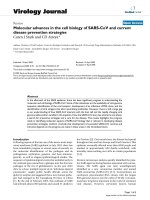
The thick-adherend test, Figure
4.1,
is most widely used because of its ease
of
manufacture and testing. Stress concentrations present in this specimen
[2]
are
limited in range and alleviated by plastic yielding of the adhesive. Consequently, a
more uniform stress field conducive to obtaining material property allowables is
obtained. Allowables and design data such as strain-to-failure, ultimate shear
strength, yield stress and shear modulus can be obtained from this test. The
manufacturer may also provide data from tests performed at various temperatures
and after saturation of the adhesive with moisture.
However, the test may not suitable for brittle adhesives because of the stress
concentrations near the ends of the bondline
[4].
For most structural adhesives,
however, especially those that are rubber-toughened, the thick-adherend test is
more than adequate [5,6]. This technique has been adapted to provide data on the
strain rate sensitivity of adhesives
[7].
An international standard similar to ASTM D5656 is
IS0
11003-2
“Adhesives
-
Determination of Shear Behaviour of Structural Bonds, Part
2:
Thick-Adherend
Tensile-Test Method”. The
IS0
standard advises the use of extensometers similar
to those recommended in ASTM D5656. The major difference between the two
standards is in the geometry of the specimen. The specimen in
IS0
11003-2
has a
shorter overlap length and thinner adherends than the specimen in ASTM D5656-
95. The types of design allowables that can be obtained from shear stress-strain
testing depend on the design method followed. If the Hart-Smith design
methodology [8] is used the adhesive is idealised as elastic/perfectly plastic. The
90
Advances in the bonded composite repair
of
metallic aircraft structure
T
30;
7
20
10-
0-
t
-
I
I
I
,
I
I
0.0
0.1
0.2
0.3
0.4
Fig.
4.1.
Schematic diagram
of
the thick-adherend test and shear stress-shear strain curves
for
adhesive
FM
73
at two temperatures obtained using this specimen, taken from reference
[9].
advantage
of
this technique is that relatively simple design formulae result and that
the ability
of
the adhesive to undergo considerable plastic flow and thus lead to
higher joint strengths
is
incorporated. Since, as Hart-Smith argues
[SI,
the
maximum potential bond strength is determined by the ultimate adhesive strain
energy in shear per unit bond area (area under the shear stress/shear strain curve),
the type of idealisation is not as important as the value
of
the ultimate shear energy
(provided this is preserved in the idealisation). The type of design allowables
obtainable using this method are listed in Table 4.1.
These allowables and their relationship to an actual stress-strain curve are shown
in Figure 4.2.
Table
4.1
Hart-Smith’s stressstrain design allowables.
Design allowable Symbol
“elastic” shear strain limit
Ye
plastic shear strain
YP
plastic shear stress (MPa)
2,
modulus in shear
(MPa)
G
Chapter
4.
Adhesives characterisation and data base
91
actual stress
i
strain curve
1
fLI
actual stress
I
I
//
strain curve
liL
Hart-Smith elastidperfectly
plastic idealisation
I/
Y
Fig.
4.2.
Hart-Smith
[8]
type idealisation
of
an adhesive stress-strain curve
Pure
tension
Obtaining
in situ
measurements of the stress-strain behaviour
of
adhesives in
bonded joints is problematic because
of
the triaxial stresses developed at the joint
edges
[lo].
The stress concentration at the edges of butt joints renders the data
obtained invalid for design purposes. Data can be obtained from neat adhesive
specimens but care must be taken in its use. Such data can be used only in the
context of a material deformation model that accounts for the highly constrained
nature
of
the adhesive in a bonded joint (see the next section) and the strain rate.
Figure
4.3
shows some neat stress-strain data obtained at two different strain rates.
Similar data can be found in other work
[ll].
Combined
shear-tensionlcompression
The actual stress state of the adhesive in a bonded repair is most likely to be one
of combined shear and tension/compression. Repairs to curved surfaces can
develop large through-thickness tensile stresses in the adhesive layer as well as shear
stresses, Chapter
7.
However, even repairs to flat surfaces will develop these stresses
though to a lesser extent.
Also,
the relatively low modulus adhesive is constrained
92
Advances
in
the bonded composite repair
of
metaNic aircraft structure
A
A
~O-~IS
strain
rate
-0-
10%
strain rate
:;o
All"
u
h
m
a
30-
20
-
10
-
0-
E.
u)
!??
-Y
u)
-0.005
0.000
0.005
0.010
0.015
0.020
0.025
0
strain
30
Fig.
4.3.
FM73
adhesive tensile test results (specimens not taken
to
failure).
by stiff adherends and this imparts a triaxial constraint on the adhesive leading to
the development of hydrostatic stresses within the adhesive.
The adhesives used in bonded repairs are often required to carry a high level of
stress and may suffer yielding. Since the yield behaviour of many polymers is
known to be sensitive to hydrostatic pressure, it is no surprise that the yield
behaviour of the Cytec adhesive FM73 is also pressure sensitive. Clearly, a yield
criterion that can properly account for the effect of hydrostatic stresses is needed
for bonded repair studies.
A
recent study [12] of the
in
situ
yield behaviour of the
adhesive FM73 subject to combined
shear-tension/compression
showed that the
modified Drucker-Prager/Cap Plasticity model correlated best with measured data
for the adhesive FM73. The Drucker-Prager/Cap Plasticity model is more
commonly associated with geological materials but performed better than more
conventional models modified to include pressure sensitivity such as the modified
von Mises and the modified Tresca models. The specimen used in this study was a
modified Iosipescu specimen
[
131, which was capable of applying combined shear
and peel stresses. Yield data from a range
of
shear and peel stress combinations
were obtained. Various yield criteria, some such as von Mises and Tresca modified
to include pressure-dependent yield, have been proposed
[
14,151 for adhesives. The
Drucker-Prager criterion has also been proposed [16]. However,
as
shown in
Figures
4.4
and 4.5 (from reference
[
12]), the modified Drucker-Prager/Cap
Plasticity works best for the rubber-modified structural epoxy adhesive FM73 (the
modified Tresca is very similar to the modified von Mises plot).
Thus for design of bonded repairs that are subject to complex loading, the
multiaxial material model used should be the modified Drucker-Prager/Cap
Plasticity model. This type of yield criterion can be implemented in a finite element
code such as
ABAQUS
[17]. The parameters (for details on the physical meaning of
these parameters see references [12,17]) needed for this criterion are given in Table
4.2.
Chapter
4.
Adhesives characterisation and data base
1I'I~I'l.l.l.lt
3
40-
a.
z.
35-
$.
6
30-
v)
a,-
%
25-
93
.$
10-
u.
W
constrained tension
-
-
c
-
s
151
m
hear tension
shear
f
pure shear
r,
neat tension
rm
=
38.6
+
1.13"~
i
neat compression
compression
Hydrostatic pressure (negative value
of),
-p,
(MPa)
Fig.
4.4.
Modified von
Mises
yield
criterion curve
fit.
80
X
Neat tension
Neat compression
Constrained tension
Constrained shear-compression
Constrained shear-tension
Constrained simple shear
Linear Drucker-Prager surface
Transition yield surface
Compression yield surface
"
-3
0
-1
5
0
15
30
Hydrostatic pressure
p
(MPa)
Fig.
4.5.
Modified
Drucker-Prager/Cap Plasticity curve
fit.
Although yield stress data does exist, there
is
little strain-to-failure data under
complex loading for adhesives. Current design practice is to knockdown pure shear
data by a factor as much as one half. This is clearly an area that needs further
development but is complicated by the triaxial stress states that develop in bonded
joints when any stress state other than pure shear is applied.
94
Advances in the bonded composite repair of metallic aircraft structure
Table
4.2
Modified Drucker-Prager/Cap plasticity parameters
for
FM73.
0.778
69.3
86.5
8.0
1.0
0.18
4.3.
Fatigue loading
Fatigue data ideally should be gathered from a bonded joint that is
representative of the repair under design, and this approach for composite
adherends is discussed in Chapter
5.
However, simple endurance testing of
adhesives is often undertaken using the single-overlap shear specimen. Although
ASTM
D3
166
describes a test method using a metal-to-metal single-lap joint for
investigating the fatigue strength of adhesives in shear, the actual stress state of
the specimen is one of combined peel and shear and the length of the overlap is
too short to properly reproduce the large strain gradients present in bonded
repairs.
For the model joints (which are designed to have uniform shear in the adhesive)
repeated cyclic stressing to high plastic strain levels can result in creep failure of the
joint after a relatively small number of cycles [18]. This is because cyclic shear
strains are cumulative. (If the cycle rate is high, full strain recovery cannot occur
during the unloading cycle.) The result is an accelerated creep failure of the
adhesive by a
strain
ratcheting
mechanism. In practical lap joints this situation is
avoided by maintaining a sufficiently long overlap,
so
that much of the adhesive
remains elastic. The elastic region on unloading acts as an elastic reservoir to
restore the joint to its unstrained state preventing the damaging strain
accumulation. Fracture mechanics approaches to measuring fatigue properties
can also be taken as described in Section
4.4.3.
4.4.
Fraeture-mechanics allowables
At present the use of fracture mechanics to evaluate the strength and durability
of adhesive joints is not highly developed. Its application is complicated by factors
such as geometric non-linearity in test specimens and mixed failure loci (cohesive
failure
of
the adhesive mixed with interfacial failure). Nevertheless, high loads may
induce static propagation of the disbond and similarly repeated loading can cause
fatigue. Consequently fracture mechanics design allowables may become useful.
The types of specimens useful for fracture mechanics studies of adhesive are shown
in Figure
4.6.
Chapter
4.
Adhesives characterisation and data
base
95
CLS
-L-L-
h2
1
w
-
-
STRAIN
GAUGE
s
w
(0
a
Y
w
K
>
Z
W
k
(0
W
0
0
s
-
MODE
If
STRAIN
ENERGY RELEASE
RATE
Fig.
4.6.
Types
of specimen used for measurement of fracture properties
in
laminated composites and
bonded joints, showing the percentage of mode
1;
adapted from reference
[19].
DCB
=
double cantilever
beam, CLS
=
cracked Shear specimen,
MMF
=
mixed mode flexural,
ENF
=
edge notced flexural.
4.4.1.
Static loading
If
a disbond is present in a bonded repair then it is typically subject to mixed
mode loading (usually a combination
of
Mode
I
and Mode
I1
and sometimes Mode
111).
However, test standards only exist for Mode
I
loading. Since adhesives used in
repair are usually very tough
(GIc
>
2W/m2) static crack propagation in the
adhesive is unlikely for most repairs to composites where
GI~
<
150
J/mz.
4.4.2.
Mode
I
ASTM standard
D3433
covers the measurement
of
Mode
I
fracture toughness.
Either flat or tapered adherend double-cantilever beam specimens can be used to
measure toughness.
For
toughened adhesives such as
FM73
the value
of
toughness
varies with bondline thickness as shown in Figure
4.7
(tapered cantilever beam
results).
6
3
E
1500-
2000-
Q)
c
8
E
2
1000-
$
500-
C
Q)
C
E
0-
4-
ln
Fig.
4.7.
Mode
I
fracture toughness
of
FM73 from
a
cantilever beam specimen
(cure
8
h
at 80
"C).
*
.**.
n-
*
-
0.1
mm
adhesive thickness
0.4
mm
adhesive thickness
-
4.4.3.
Mode
I1
and mixed mode
Fracture mechanics testing of adhesives, from pure Mode
I
through mixed Mode
I/Mode
I1
through to pure Mode
I1
can be performed using the test specimen and
loading
rig
developed by Fernlund and Spelt
[20].
Mode
I1
tests, however, are
difficult to perform for most toughened adhesives as yield of metallic adherends
often occurs before the adhesive undergoes crack propagation.
4.4.4.
Fatigue loading
Data on fatigue damage threshholds and crack propagation under fatigue
loading are most usually obtained from the fracture mechanics-type lap-joint tests
using
an
edge-notched flexural specimen
[21]
for Mode
11,
the double-cantilever
beam specimen for Mode
I
and cracked lap-shear specimen for mixed mode (see
Figure
4.6).
In these tests the rate of crack propagation in the adhesive is usually
plotted as a function of the strain-energy-release-rate range. The empirical
relationship between the range of strain-energy-release rate and the crack growth
rate is of the form:
da
dN
-=AAG"
,
where
a
is
the disbond or crack length in the adhesive,
N
the number of fatigue
cycles, and
AG
the range of strain energy release rate for the relevant mode. The
parameters
A
and
n
are empirically determined constants.
In
the mixed-mode
specimens, Figure
4.8,
it was found that the better correlation is with the total
strain energy range
AGT,
showing that Modes
I
and
I1
contribute to damage
growth. Figure
4.8
shows a typical result for the adhesive FM
300.
Chapter
4.
Adhesives characterisation and data base
loA
IOd
W7
da
dN
mlcycle
10"
o-9
10-'O
97
-
200
-1
FM300
-
DEBOND
mu
a
5
8
150
-
%
(I)
0)
W
w
k-
\I
;
~
G,,,=
87
jIm2
NO DEBO"
a.
w
98
Advances
in
the bonded composite repair of metallic aircraft structure
AGT~
was taken as the strain-energy release range for a disbond propagation rate of
10-9m/cycle. For FM300 the value of
AGTh
was found to be 87J/m2 at this
propagation rate.
Generally, as shown in Figure 4.8(b), the correlation was very good between the
predicted and observed cyclic stress levels for disbond growth for the various taper
angles, indicating the potential of this approach for fatigue-critical joints having a
significant Mode
I
(peel) component. Sensitivity to adhesive thickness and other
joint parameters remains to be demonstrated.
4.5.
FM73
database
4.5.1
In situ
shear stressstrain allowables
To
reduce thermal residual stresses in bonded repairs or to ease application
problems,
a
cure of 8h at
80°C
of
FM73
is often used in contrast to the
manufacturer's recommended
1
h at 120
"C.
Thus in the test specimen this was the
cure temperature used and the pressure applied during cure was 100 kPa also to
simulate in-field repairs. The surface treatment used was the standard solvent clean,
grit blast and application of aqueous silane-coupling agent
[9].
The data from
testing
30
test specimens
[9]
at each test condition (-40
"C
dry, 24
"C
dry and
80
"C
wet) is shown below in Table 4.3. It is reported in both the form recommended in
ASTM
5656
and in the form advocated by Hart-Smith (elastic-perfectly plastic
idealisation)
-
the latter being the more useful for design purposes. The standard
deviation is shown for the value reported.
Hart-Smith
[8]
type design allowables are shown in Table 4.4.
Table
4.3
FM73
stressstrain data
[9]
and standard deviations for three test conditions
(8
h
at
SOT,
lOOkPa
pressure cure condition).
RT
dry
-40
"C dry
80 "C
wet
Linear limit shear stress (MPa)
Linear limit shear strain
Shear modulus (MPa)
Knee value
of
shear stress (MPa)
Knee value
of
shear strain
Knee shear modulus (MPa)
Ultimate shear stress (MPa)
Ultimate shear
strain
27.34
f
1.21
0.0364
+
0.0022
805.47
f
38.84
39.22
f
0.96
0.0739
f
0.0028
530.7
f
23.9
39.14
f
1.76
0.5774
&
0.0475
27.23
f
4.72
0.0302
f
0.0068
959
f
150
50.27
f
2.45
0.0688
f
0.0079
730.7
f
91.1
55.71
&
2.14
0.1870
f
0.0415
5.97
f
2.95
0.0207
f
0.0054
278
f
134
8.95 3.1
1
0.0546
f
0.0121
163.9
f
67.6
21.85
f
3.83
0.8630 0.1013
Chapter
4.
Adhesives characterbation and data base
99
Table
4.4
Hart-Smith
type
design allowables for
FM73
cured at
80
"C for
8
h.
RT, dry -4O"C, dry
80°C,
wet
Elastic shear strain
0.0804
k
0.0151
0.0723
f
0.0082 0.6616
f
0.1214
Shear modulus (MPa)
503
f
88
791
f
107 34.8
f
13.9
Yield stress (MPa)
41.52
k
0.97
56.46
f
2.15 21.88
f
3.46
Plastic shear strain
0.4970
k
0.0468
0.1192
f
0.0261 0.2014
&
0.1035
4.5.2. Yield criterion
A report by Wang and Chalkley
[12]
details an investigation of the yield
behaviour of
FM73
(1
h at
120
"C
cure). An experimental investigation, using the
modified Iosipescu specimen loaded at various angles and various neat adhesive
tests was undertaken. Yield criteria investigated include modified Tresca, modified
von Mises, modified Mohr-Coloumb, modified Drucker-Prager and modified
Drucker-Prager with cap plasticity. The last criterion was found to best fit the data
and the resulting yield parameters are shown in Table
4.5.
4.5.3. The glass transition temperature
Studies at AMRL using dynamic mechanical thermal analysis
(DMTA)
have given
the following estimates for the glass transition temperature of FM73 (Table
4.6).
Table
4.5
Modified Drucker-Prager/cap plasticity parameters for
FM73.
K
fl
(degrees)
d(MPa)
pa
(MPa)
R
a
0,778 69.3
86.5 8.0
1.0
0.18
Table
4.6
Glass transition temperature data for
FM73.
FM73
-
1
h at
120°C
cure
FM73
-
8
h at
80°C
cure
99.7
"C
108.5
"C
100
Advances in the bonded composite repair
of
metallic aircraft structure
4.5.4.
Fickean diffusion coeflcients for moisture absorption
Althof
[24]
gives the following data for the diffusion coefficients of FM73 (Table
Althof's bulk adhesive film specimens had dimensions
1
mm
x
60
mm
x
10 mm.
This size of specimen conforms to
DIN
53445 (torsion-vibration tests). The
aluminium plate specimens had dimensions 5mm
x
100mm, lOmm
x
100mm,
20mm
x
IOOmm, and 30mm
x
100mm. The number of specimens per data point
is not reported. Althof's data is also reported by Comyn [25], which an easier
reference to obtain.
Jurf and Vinson
also
give data for the adhesive FM73-M (FM73 having a matt
scrim) and their data is given in Table
4.8.
4.7).
4.5.5.
Mode
I
fracture toughness
Fracture toughness data for the
8
h at
80
"C-cure condition
(24
"C
test
Table 4.10 presents the fracture toughness measured for the 1 h at
120°C
cure
Note that the
8
h
at
80
"C cure of the adhesive results in a more brittle adhesive.
temperature) is presented in Table
4.9.
condition.
Table
4.7
Althof's
[24]
Fickean moisture diffusion coefficients for
FM73.
Temp
(
"C)
20
20
40
40
50
70
Relative
humidity
(a)
70
95
70
95
95
95
Max.
moisture
content
(%)
1.1
2.0
1.2
2.5
2.5
1
0"
Diffusion coefficients
obtained from water
absorption by adhesive film
experiments (m's-')
2.8
10-l~
1.7
10-l~
8.1
10-l~
4.2
10-13
11.6
10-l3
-
Diffusion coefficients
obtained from
in
situ
absorption between
aluminium plates
experiments
(rn's-')
3.6
10-13
3.9 10~3
10.3
10-13
41.7 10-1~
15.2 10-1~
33.3
10-l~
"Althof reports this value as an abnormal increase in moisture.
Table
4.8
Jurf
and Vinson's
[26]
moisture diffusion coefficients for
FM73-M.
Temperature Relative Diffusion coefficient Saturation moisture
(
"C)
humidity
(%)
(rn's-I)
content
(a)
38 95 6.2
x
io-" 1.55
49 95 8.0
10-l~ 2.05
71 95 9.8
10-13
2.30
60 95
8.7
10-13 2.20
Chapter
4.
Adhesives characterisation and data base
Table
4.9
Author's mode
I
fracture toughness data for
FM73
cured for
8
h at
80
"C.
Adhesive Minimum fracture
Maximum
fracture Average fracture
thickness (mm) toughness (J/m')
toughness (J/m2) toughness (J/m2)
0.1 1113
0.4 1502
0.9 1906
1230 1172
1790 1646
2903 2405
Table
4.10
Mode
I
fracture toughness data for
FM73 [27]
(1
h at
120°C
cure).
Temperature ("C) Mode
I
fracture toughness (J/m*)
101
21
3000
-40
2700
References
1.
Chalkley, P.D. and Baker,
A.
(1999).
Development
of
a generic repair joint
for
the certification of
bonded repairs.
Int. J.
of
Adhesion and Adhesives
19,
121-132.
2.
Anderson, G.P.
(1984).
Evaluation
of
adhesive test methods. In
Adhesive Joinfs
-
Formation,
Characteristics and Testing
(K.L.
Mittal, ed.) Plenum Press, New York.
3.
Wycherley, G.W., Mestan, S.A. and Grabovac,
I.
(1990).
A Method for Uniform Shear Stress-
Strain Analysis of Adhesives, ASTM JOTE, May.
4.
Grabovac,
I.
and
Morns,
C.E.M.
(1991).
The application of the Iosipescu shear test to structural
adhesives.
J.
of
Applied Polymer Science,
43, 2033-2042.
5.
Renton, W.J.
(1976).
The symmetric lap-shear test
-
What good is it?
Experimental Mechanics,
Nov.
pp.
409415.
6.
Tsai,
M.Y.,
Morton, J., Krieger, R.B.,
et al.
(1996).
Experimental investigation
of
the thick-
adherend lap shear test.
J.
of
Advanced Materials,
April, pp.
28-36.
7.
Chalkley, P.D. and Chiu, W.K.
(1993).
An improved method for testing the shear stress-strain
behaviour
of
adhesives.
Int. J.
of
Adhesion and Adhesives,
13(4),
October.
8.
Hart-Smith, L.J.
(1973).
Adhesive-Bonded Double-lap Joints, NASA CR
112235,
Douglas Aircraft
Company, McDonnell Douglas Corporation, Long Beach, California, USA.
9.
Chalkley, P.D. and van den Berg, J.
(1997).
On
Obtaining Design Allowables
for
Adhesives
used
in
the Bonded-composite Repair of Aircraft, DSTO-TR-0608, Defence Science and Technology
Organisation, Melbourne.
10.
Adams, R.D., Coppendale, J. and Peppiatt, N.A.
(1978).
Stress analysis of axisymmetric butt joints
loaded in torsion and tension.
J.
of
Strain Analysis,
13(1).
11.
Butkus, L.M.
(1997).
Environmental Durability of Adhesively Bonded Joints, Ph.D. Thesis, Georgia
Institute
of
Technology, September.
12.
Wang, C.H. and Chalkley, P.D.
(2000).
Plastic yielding of a film adhesive under multiaxial stress.
Int.
J. offdhesion and Adhesives,
20(2),
April, pp.
155-164.
13.
Broughton, W.R.
(1 989).
Shear Properties
of
Unidirectional Carbon Fibre Composites, Ph.D.
Thesis, Darwin College, Cambridge.
14.
Haward, R.N.
(1973).
The Physics
of
Ghsy Polymers,
Applied Science Publishers Pty. Ltd.,
London.
15.
Bowden, P.B. and Jukes, J.A.
(1972).
The plastic
flow
of isotropic polymers.
J.
of
Materiais Science,
7,
pp.
52-63.
102
Advances in the bonded composite repair of metallic aircraft structure
16.
Chiang, M.Y.M. and Chai, H.
(1972).
Plastic deformation analysis of cracked adhesive bonds
17.
ABAQUS
(1997).
Theory Manual, Version
6.5.
Hibbitt, Karlsson
&
Sorensen Inc., USA.
18.
Hart-Smith, L.J.
(1981).
Difference Between Adhesive Behaviour in Test Coupons and Structural
Joints, Douglas Paper
7066,
presented to ASTM Adhesives Committee, Phoenix.
19.
Russell, A.J. and Street, K.N.
(1985).
Moisture and temperature effects
on
the mixed mode
delamination fracture of unidirectional graphitelepoxy.
Delamination and Disbonding
of
Materials
(W.S.
Johnson, ed.) ASTM
STP
876.
20.
Fernlund,
G.
and Spelt, J.K.
(1994).
Mixed-mode fracture characterisation of adhesive joints.
Composites Science and Technology,
50,
pp.
44449.
21.
Russell, A.J. Fatigue crack growth in adhesively bonded graphite/epoxy joints under shear loading.
ASME Symposium
on
Advances in Adhesively Bonded Joints
1988,
MD
6
(S.
Mall, K.M. Liechti and
J.R. Vinson, eds.) (Book
No
G00485).
22.
Lin, C. and Liechti, K.M.
(1987).
Similarity concepts in the fatigue fracture
of
adhesively bonded
joints.
J.
of
Adhesion,
21,
pp.
1-24.
23.
Johnson, K.W.S. and Dillard, D.A.
(1987).
Experimentally determined strength of adhesively
bonded joints in joining fibre reinforced plastics (F.L. Mathews, ed.) Elsevier Applied Science
pp.
105-183.
24.
Althof,
W. (1980).
The Diffusion of Water Vapour in Humid Air into the Adhesive Layer of Bonded
Metal Joints, DFVLR-FB
79-06, 1979
-
RAE translation into English
no.
2038,
February.
25.
Comyn, J.
(1981).
Joint durability and water diffusion.
In
Developments in Adhesives
-
2
(A.J.
Kinloch, ed.) Applied Science Publishers, London.
26.
Jurf,
R.A. and Vinson, J.R.
(1985).
Effect of moisture
on
the static and viscoelastic properties of
epoxy adhesives.
J.
of
Materials Science
20,
pp.
2979-2989.
27.
Baker, A.A., Chester, R.J., Davis, M.J.,
et al.
(1993).
Reinforcement of the
F-111
wing pivot fitting
with a boron/epoxy doubler system
-
Materials engineering aspects.
Composites
24(6),
pp.
51
1-521.
loaded in shear.
Int.
J.
of
Soli& and Structures,
31,2477-2490.
Chapter
5
FATIGUE TESTING
OF
GENERIC BONDED JOINTS
P.D.
CHALKLEY,
C.H.
WANG
and
A.A.
BAKER
Defence Science and Technology Organisation, Air Vehicles Division, Fishermans
Bend, Victoria
3207,
Australia
5.1.
Introduction
A
certification process has been proposed
El]
(see also Chapter
22)
based largely
on a generic approach to patch design, validation and the acquisition
of
materials
allowables. This approach includes testing of joints representing the repaired
region. This chapter reports on the development
of
and preliminary results for two
such generic bonded joints
to
be used in the validation process: the double overlap-
joint fatigue specimen
(DOFS)
and the skin doubler specimen
(SDS).
These two
joints are selected to represent parts
of
the bonded repair with widely differing
damage-tolerance requirements as discussed later in this chapter.
The layout of this chapter is as follows. The role
of
the two representative joints
within the generic design and certification process is established. Then the damage-
tolerance requirement for the structure that each joint represents is discussed. The
specimen preparation and manufacture are outlined for each joint
in
turn. The
stress-state
of
the specimen is analysed. The experimental method and test results
are reported and the suitability of various fatigue-correlation parameters is
discussed. Finally the suitability/limitations of the specimens for generic design and
certification is discussed and further work is suggested before concluding.
5.1.1.
Damage-tolerance regions in a bonded repair
Figure
5.1
shows a schematic
of
a bonded repair to a cracked plate for which
Baker
[I]
proposed that two distinctly different regions exist in terms of structural
integrity requirement.
The central damage-tolerant region is the zone where a significant disbond
between the patch and plate can be tolerated. This is because small disbonds reduce
Baker, A.A., Rose, L.R.F. and Jones,
R.
(eds.),
,
103
Advances in the Bonded Composite Repairs of Metallic Aircraft Structure
Crown Copyright
0
2002
Published by
Elsevier
Science
Ltd. All rights reserved.
104
Advances in the bonded composite repair of metallic aircraft structure
I
Fig.
5.1.
Damage-tolerant and safe-life zones
in
a
bonded repair.
the repair effectiveness only slightly and disbond growth under repeated loading is
slow and stable. The ends of the patch are stepped, thinning down to one ply of
fibre composite at the edges. In this zone disbonds cannot be tolerated because as
the disbond grows it moves into a region of increasing patch thickness and
consequently greater driving force for disbond growth. The result may be rapid
disbond growth resulting in patch separation.
To represent these two regions testing of two types of generic joint was proposed:
0
The double overlap-joint fatigue specimen (DOFS), which represents the
damage-tolerance region where the patch spans the crack
0
The skin doubler specimen (SDS), which represents the safe-life region at the
termination of the patch.
Both specimens have fibre-composite outer adherends on both sides of an
aluminium inner adherend to represent bonded repairs to aircraft structural plate
where there is substantial out-of-plane restraint from substructure such as stringers,
stiffeners or honeycomb core.
5.1.2.
The generic design and certification process
Table
5.1
places the two generic repair joints, the DOFS and the SDS, in the
context of the certification process.
5.2.
The
DOFS
Details on the materials and geometry
of
the DOFS are provided in Figure
5.2.
The DOFS were manufactured by bonding the outer composite adherends to the
aluminium inner adherends with adhesive FM73 and then cutting into three
individual specimens. The inner adherends were made from aluminium alloy
2024-
T3 (bare). Surface treatment of the aluminium plates, prior to adhesive bonding,
was the solvent clean, grit blast, silane treatment described in Chapter 3. The
boron/epoxy
(120°C
cure system) outer adherends were cocured with a layer of
Chapter
5.
Fatigue testing of generic bonded joints
105
Table
5.1
Generic joint test program to obtain repair system allowables, taken from reference
[l].
Requirement Approach
To find joint static and fatigue strain allowables
and confirm validity of failure criteria based on
coupon test data. coupon data
The failure damage criteria must hold for similar
geometrical configurations, e.g. adherend thickness
and stiffness and adhesive thickness.
0
Undertake static strength tests to:
-
check strength against predictions based on
0
Undertake fatigue tests to:
-
obtain B-basis threshold for fatigue disbond
growth
-
determine disbond growth rates under constant
amplitude and spectrum loading
I
I
0
Find knockdown factors for:
Double overlap-joint fatigue specimen (DOFS)
representing cracked region
a$-\d
-
hot/wet conditions
-
non-optimum manufacture
-
typical damage
-
more representative loading conditions
Skin doubler specimen (SDS), representing patch
termination
A
aluminium
alloy inner
adherend
knife edges
t
structural
flim
adhesive
such
as
M73
-
ti=6.4
mm
t0=1.17
mm
teflon film
starter crack
length
30
mm
nine plies
of
borodepoxy
outer adherend
Fig.
5.2.
The double-overlap-joint fatigue specimen (DOFS).
106
Advances in the bonded composite repair of metallic aircraft structure
FM73 at
120
"C
then grit blasted and bonded to the aluminium plates at
80
"C
with
another layer of FM73. The cocured adhesive layer is used to prevent damage
to
the boron/epoxy during the grit-blasting process and to toughen the matrix surface
layer of the composite. All bonding was done in an autoclave.
5.2.1.
Stress state
in
the
DOFS
A finite element (FE) analysis of the DOFS
121
showed, as expected, that the joint
is essentially in a state of shear plus transverse compression (to the plane of the
adhesive), referring to Figure 5.3. The FE results were obtained based on the
assumed material properties listed in Table
5.2.
I
DOFS
Lines: spring-beam theory
-Shear stress
20
-10
Or-
-20
[
1
0
5 10 15
20
Distance from centre
of
joint
(mm)
Fig. 5.3. Plot
of
shear and peel stresses along the mid-plane
of
the adhesive layer in DOFS; load/unit
width
=
1
kN/mm. (neglecting thermal residual stresses).
Table 5.2
Material properties used in the
DOFS
and
SDS
analyses.
Adhesive Aluminium Boron/Epoxy
GR
=
800
MPa Ei=71GPa
E,
=
193 GPa
VA
=
0.35
vi
=
0.33
EZ2
=
19.6 GPa
aA
=
66
x
IOp6
(per "C)
ai=
24
x
(per "C)
G12
=
5.5GPa
v,2=0.21
v21=
0.021
a1,=4.3
x
(per°C)
a22
=
15.6
x
(per "C)
tA
=
0.4 mm
ti
=
6.4
~lllll
to
=
1.1 mm