Aircraft structures for engineering students - part 6 potx
Bạn đang xem bản rút gọn của tài liệu. Xem và tải ngay bản đầy đủ của tài liệu tại đây (2.45 MB, 61 trang )
9.2
General stress, strain and displacement relationships
291
3
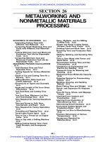
Fig.
9.13
Distribution
of
direct stress in Z-section beam
of
Example
9.3.
deform the beam section into a shallow, inverted
's'
(see Section
2.6).
However, shear
stresses in beams whose cross-sectional dimensions are small in relation to their
lengths are comparatively low
so
that the basic theory of bending may be used
with reasonable accuracy.
In thin-walled sections shear stresses produced by shear loads are not small and
must be calculated, although the direct stresses may still be obtained from the basic
theory of bending
so
long as axial constraint stresses are absent; this effect is discussed
in Chapter
1 1.
Deflections in thin-walled structures are assumed to result primarily
from bending strains; the contribution of shear strains may be calculated separately
if required.
e
6
Istress,
^st
r a i'n an
d-dEplace
me
nt
re
la
t
i
o
ns h
i
ps
for
open and single cell closed section thin-walled
beams
We shall establish in this section the equations of equilibrium and expressions for
strain which are necessary for the analysis
of
open section beams supporting shear
loads and closed section beams carrying shear and torsional loads. The analysis of
open section beams subjected to torsion requires a different approach and is discussed
separately in Section
9.6.
The relationships are established from first principles for the
particular case of thin-walled sections in preference to the adaption of Eqs
(1.6),
(1.27)
and
(1.28)
which refer to different coordinate axes; the form, however,
will
be seen
to
be the same. Generally, in the analysis we assume that axial constraint
effects are negligible, that the shear stresses normal to the beam surface may be
neglected since they are zero at each surface and the wall is thin, that direct and
shear stresses on planes normal to the beam surface are constant across the thickness,
and finally that the beam is of uniform section
so
that the thickness may vary with
distance around each section but is constant along the beam. In addition, we ignore
squares and higher powers of the thickness
t
in the calculation of section constants.
292
Open and closed, thin-walled beams
(a)
(bl
Fig.
9.14
(a) General stress system on element
of
a closed or open section beam; (b) direct stress and shear
flow
system on the element.
The parameter
s
in the analysis is distance measured around the cross-section from
some convenient origin.
An element
6s
x
6z
x
t
of the beam wall is maintained in equilibrium by a system
of
direct and shear stresses as shown in Fig. 9.14(a). The direct stress
a,
is produced by
bending moments or by the bending action
of
shear loads while the shear stresses are
due to shear and/or torsion of a closed section beam or shear of
an
open section beam.
The hoop stress
us
is usually zero but may be caused, in closed section beams, by inter-
nal pressure. Although we have specified that
t
may vary with
s,
this
variation is small
for most thin-walled structures
so
that we may reasonably make the approximation
that
t
is constant over the length
6s.
Also,
from
Eqs
(1.4), we deduce that
rrs
=
rsz
=
r
say. However, we shall find it convenient to work in terms of
shear
flow
q,
i.e. shear force per unit length rather than in terms of shear stress. Hence, in
Fig. 9.14(b)
q
=
rt
(9.21)
For equilibrium of the element in the
z
direction and neglecting body forces (see
and is regarded as being positive in the direction of increasing
s.
Section 1.2)
(a,
+z6r)*6s
-
azt6s
+
(2)
q+-&
sz
-
qsz
=
0
which reduces to
a4
aaz
as
az
-+t-=O
Similarly for equilibrium in the
s
direction
(9.22)
(9.23)
The direct stresses
a,
and
us
produce direct strains
E,
and
E,,
while the shear stress
r
induces a shear strain
y(=
T~~
=
T,,).
We shall now proceed to express these strains in
terms of the three components of the displacement of a point in the section wall (see
Fig. 9.15).
Of
these components
v,
is
a tangential displacement in the
xy
plane and is
taken to be positive in the direction of increasing
s;
w,,
is a normal displacement in the
9.2
General stress, strain and displacement relationships
293
X
z
Fig.
9.15
Axial, tangential and normal components
of
displacement
of
a point in the beam wall.
xy
plane and is positive outwards; and
w
is an axial displacement which has been
defined previously in Section 9.1. Immediately, from the third of
Eqs
(1.18), we have
dW
az
&
=-
(9.24)
It is possible to derive a simple expression for the direct strain
E,
in terms of
ut,
wn,
s
and the curvature
1/r
in the
xy
plane of the beam wall. However, as we do not require
E,
in the subsequent analysis we shall, for brevity, merely quote the expression
aV,
vn
&
=-+-
as
r
(9.25)
The shear strain
y
is found in terms of the displacements
w
and
ut
by considering the
shear distortion of an element
6s
x
Sz
of the beam wall. From Fig. 9.16 we see that the
shear strain is given by
7
=
41
+
42
or, in the limit as both
6s
and
Sz
tend to zero
(9.26)
Fig.
Distorted shape
of
element due
\ **-
to shear
f:.
1
_
L.
I
.
4
_
9.16
Determination
of
shear strain
y
in terms
of
tangential and axial components
of
displacement.
294
Open and closed, thin-walled beams
Fig.
9.17
Establishment
of
displacement relationships and position
of
centre
of
twist
of
beam (open or
closed).
In addition to the assumptions specijied in the earlier part of this section, we further
assume that during any displacement the shape of the beam cross-section is main-
tained by a system of closely spaced diaphragms which are rigid in their
own
plane
but are perfectly flexible normal to their own plane
(CSRD
assumption). There is,
therefore,
no
resistance to axial displacement
w
and the cross-section moves as a
rigid body in its own plane, the displacement of any point being completely specified
by translations
u
and
21
and a rotation
6
(see Fig.
9.17).
At first sight this appears to be a rather sweeping assumption but, for aircraft struc-
tures of the thin shell type described in Chapter
7
whose cross-sections are stiffened by
ribs or frames positioned at frequent intervals along their lengths, it is a reasonable
approximation for the actual behaviour of such sections. The tangential displacement
vt
of any point
N
in the wall of either an open or closed section beam is seen from Fig.
9.17
to be
v,
=
p6
+
ucos
$
+
vsin
$
(9.27)
where clearly
u,
w
and
B
are functions of
z
only
(w
may be a function of
z
and
s).
The origin
0
of the axes in Fig.
9.17
has been chosen arbitrarily and the axes suffer
displacements
u,
w
and
0.
These displacements, in a loading case such
as
pure torsion,
are equivalent to a pure rotation about some point R(xR,YR) in the cross-section
where R is the
centre
of
twist.
Thus, in Fig.
9.17
and
(9.28)
pR
=
p
-
xR sin
1(,
+
yR cos
$
which gives
9.3
Shear
of
open section
beams
295
and
dv,
de de de
-
=
p
-
-
XR
sin
+-
+
yR
cos
+-
dz dz dz dz
Also from
Eq.
(9.27)
de du dv
.
3
=
p-
+
-cos
+
-sm
+
dz dz dz dz
Comparing the coefficients of
Eqs
(9.29) and (9.30) we see that
dvldz duldz
dO/dz
I
YR
=-
dQ/dz
XR
=
(9.29)
(9.30)
(9.31)
The open section beam
of
arbitrary section shown in Fig. 9.18 supports shear loads
S,
and
Sy
such that there is
no
twisting of the beam cross-section. For this condition to
be valid the shear loads must both pass through a particular point in the cross-section
known as the
shear
centre
(see also Section
11.5).
Since there are no hoop stresses in the beam the shear flows and direct stresses
acting on an element of the beam wall are related by
Eq.
(9.22), i.e.
aq
do,
-+t-=o
as
dz
We assume that the direct stresses are obtained with sufficient accuracy from basic
bending theory
so
that from
Eq.
(9.6)
acz
-
[(aM,/az)Ixx
-
(awaz)r.Xyl
+
[(aMx/wryy
-
(dMy/wx,l
dZ
IxxI,,
-
I:,
Ixxryy
-
I&
't
Fig.
9.18
Shear loading
of
open section beam.
296
Open and closed, thin-walled beams
Using the relationships of
Eqs
(9.11)
and
(9.12),
i.e.
aMy/az
=
S,
etc., this expression
becomes
(SXZXX
-
SyZxy)
+
(SyZyy
-
SxZxy)
Y
-
az
zx,zyy
-
z:y
zxxzyy
-
Ey
Substituting for
&Jaz
in
Eq.
(9.22)
gives
(9.32)
Integrating
Eq.
(9.32)
with respect to
s
from some origin for
s
to
any point around the
cross-section, we obtain
(9.33)
If the origin for
s
is taken at the open edge of the cross-section, then
q
=
0
when
s
=
0
and
Eq.
(9.33)
becomes
For a section having either
Cx
or
Cy
as an axis of symmetry
Zxy
=
0
and
Eq.
(9.34)
reduces to
Example
9.4
Determine the shear flow distribution in the thin-walled 2-section shown
in
Fig.
9.19
due to a shear load
Sy
applied through the shear centre of the section.
-
2
Fig.
9.19
Shear-loaded Z-section
of
Example
9.4:
9.3
Shear
of
open section beams
297
The origin for our system of reference axes coincides with the centroid
of
the
section at the mid-point of the web. From antisymmetry we also deduce by inspection
that the shear centre occupies the same position. Since
S,
is applied through the shear
centre then no torsion exists and the shear flow distribution is given by Eq. (9.34) in
which
S,
=
0,
i.e.
or
(Ix,
txds
-
I,,
tY
ds)
SY
qs
=
IxxI,,
-
I$
The second moments of area of the section have previously been determined in
Example 9.3 and are
Substituting these values in
Eq.
(i) we obtain
s,
qs
=
-
(10.32~
-
6.84~) ds
h3
10
(ii)
On the bottom flange 12, y
=
-h/2 and
x
=
-h/2
+
sl,
where
0
<
s1
<
h/2. Therefore
giving
(iii)
Hence at 1
(sl
=
0),
q1
=
0
and at 2
(sl
=
h/2),
q2
=
0.42SJh. Further examination
of
Eq.
(iii) shows that the shear flow distribution on the bottom flange is parabolic
with a change of sign (Le. direction) at
s1
=
0.336h. For values of
s1
<
0.336h,
q12
is negative and therefore in the opposite direction to
sl.
In the web 23, y
=
-h/2
+
s2, where
0
<
s2
<
h
and
x
=
0.
Thus
We note in Eq. (iv) that the shear flow is not zero when
s2
=
0
but equal to the value
obtained by inserting
s1
=
h/2
in
Eq.
(iii), i.e.
q2
=
0.42Sy/h. Integration
of
Eq.
(iv)
yields
S
q23
=
(0.42h2
+
3.42h.Y~
-
3.424)
This
distribution is symmetrical about
Cx
with a maximum value at
s2
=
h/2(y
=
0)
and the shear flow is positive at all points in the web.
The shear flow distribution in the upper flange may be deduced from antisymmetry
so
that the complete distribution is of the form shown in Fig. 9.20.
298
Open
and closed, thin-walled beams
0.42
S,/h
Fig. 9.20
Shear
flow
distribution in Z-section
of
Example
9.4.
9.3.1
Shear centre
We have defined the position of the shear centre as that point in the cross-section
through which shear loads produce no twisting. It may be shown by use of the
reciprocal theorem that this point is also the centre of twist of sections subjected to
torsion. There are, however, some important exceptions to this general rule as we
shall observe in Section
1 1.1.
Clearly, in the majority of practical cases it is impossible
to guarantee that a shear load will act through the shear centre of a section. Equally
apparent is the fact that any shear load may be represented by the combination of the
shear load applied through the shear centre and a torque. The stresses produced by
the separate actions of torsion and shear may then be added by superposition. It is
therefore necessary to know the location of the shear centre in all types of section
or to calculate its position. Where a cross-section has an
axis
of symmetry the
shear centre must, of course, lie on this axis. For cruciform or angle sections of the
type shown in Fig.
9.21
the shear centre is located at the intersection of the sides
since the resultant internal shear loads all pass through these points.
Example
9.5
Calculate the position of the shear centre of the thin-walled channel section shown in
Fig.
9.22.
The
thickness
t
of
the
walls
is
constant.
sc
sc
I+
Fig. 9.21
Shear centre position for type
of
open section beam shown.
9.3
Shear
of
open section beams
299
t
3
4
t
A
h
2
11
S
C
X
h
2
2u’
Fig.
9.22
Determination
of
shear centre position
of
channel section
of
Example
9.5
The shear centre
S
lies on the horizontal
axis
of symmetry at some distance
&,
say,
from the web. If we apply an arbitrary shear load
Sy
through the shear centre then the
shear flow distribution is given by Eq.
(9.34)
and the moment about any point in the
cross-section produced by these shear flows is equivalent to the moment of the applied
shear load.
Sy
appears on both sides of the resulting equation and may therefore be
eliminated to leave
&.
For the channel section,
Cx
is an axis of symmetry
so
that
Ixy
=
0. Also
S,
=
0 and
therefore Eq.
(9.34)
simplifies to
where
I
xx-
-2bt
(;y
-
+-=-
‘:1
;;(
I+-
?)
Substituting for
I,,
in Eq. (i) we have
‘”h3(1+6b/h)
-IZSy
Pds
o
(ii)
The amount of computation involved may be reduced by giving some thought to
the requirements of the problem. In this case we are asked to find the position
of
the shear centre only, not a complete shear flow distribution. From symmetry it is
clear that the moments of the resultant shears on the top and bottom flanges about
the mid-point
of
the web are numerically equal and act in the same rotational
sense. Furthermore, the moment of the web shear about the same point is zero. We
deduce that it is only necessary to obtain the shear flow distribution on either the
top or bottom flange for a solution. Alternatively, choosing a web/flange junction
as a moment centre leads to the same conclusion.
300
Open and closed, thin-walled beams
On the bottom flange,
y
=
-h/2
so
that from Eq. (ii) we have
6S,
q12
=
h2(1
+
6b/h)
s1
(iii)
Equating the clockwise moments of the internal shears about the mid-point
of
the web
to the clockwise moment of the applied shear load about the same point gives
or, by substitution from Eq. (iii)
from which
3b2
Is
=
h(1
+
6h/h)
In the case of an unsymmetrical section, the coordinates
(Js,
qs)
of the shear centre
referred to some convenient point in the cross-section would be obtained by first
determining
Es
in
a
similar manner
to
that of Example
9.5
and then finding
qs
by
applying
a
shear load
S,
through the shear centre. In both cases the choice of a
web/flange junction
as
a
moment centre reduces the amount of computation.
hear
of
closed
section
beams
The solution for
a
shear loaded closed section beam follows
a
similar pattern to that
described in Section
9.3
for an open section beam but with two important differences.
First, the shear loads may be applied through points in the cross-section other than
the shear centre
so
that torsional
as
well
as
shear effects are included. This is possible
since,
as
we shall see, shear stresses produced by torsion in closed section beams have
exactly the same form
as
shear stresses produced by shear, unlike shear stresses due to
shear and torsion in open section beams. Secondly, it is generally not possible to
choose an origin for
s
at which the value of shear flow is known. Consider the
closed section beam of arbitrary section shown in Fig.
9.23.
The shear loads
S,
and
S,.
are applied through any point in the cross-section and, in general, cause direct
bending stresses and shear flows which are related by the equilibrium equation
(9.22).
We assume that hoop stresses and body forces are absent. Thus
dq
do;
-+r-=o
as
az
From this point the analysis is identical to that for
a
shear loaded open section beam
until we reach the stage of integrating Eq.
(9.33),
namely
9.4
Shear
of
closed section
beams
301
Fig.
9.23
Shear
of
closed section beams.
Let us suppose that we choose an origin for
s
where the shear flow has the unknown
value
qs,o.
Integration of
Eq.
(9.33) then gives
or
We observe by comparison of
Eqs
(9.35) and (9.34) that the first two terms on the
right-hand side of
Eq.
(9.35) represent the shear flow distribution in an open section
beam loaded through its shear centre. This fact indicates a method of solution for a
shear loaded closed section beam. Representing this 'open' section or 'basic' shear
Aow by
qb,
we may write
Eq.
(9.35) in the
form
4.7
=
qb
+
qs,O
(9.36)
We obtain
qb
by supposing that the closed beam section is 'cut' at some convenient
point thereby producing an 'open' section (see Fig. 9.24(b)). The shear flow
Fig.
9.24
(a) Determination
of
q,,o;
(b) equivalent loading on 'open'section beam.
302
Open and closed, thin-walled
beams
distribution (qb) around this ‘open’ section is given by
as in Section 9.3. The value of shear flow at the cut
(s
=
0)
is then found by equating
applied and internal moments taken about some convenient moment centre.
Thus,
from Fig. 9.24(a)
SxVO
-
SyCO
=
fpqh
=
fpqb
dS +
qs,O
fp
dS
where denotes integration completely around the cross-section. In Fig. 9.24(a)
SA
=
~SSP
so
that
dA=$
pds
ff
Hence
pds
=
2A
f
where
A
is the area enclosed by the mid-line
of
the beam section wall. Hence
SxVO
-
S&O
=
f
Pqb
dS
f
2Aqs,O
(9.37)
If the moment centre is chosen to coincide with the lines of action of
Sx
and
Sy
then
Eq. (9.37) reduces to
=
Pqb
dS
f
2Aqs,0 (9.38)
f
The unknown shear flow
qs,o
follows from either of Eqs (9.37) or (9.38).
It is worthwhile to consider some of the implications of the above process.
Equation (9.34) represents the shear flow distribution in an open section beam for
the condition of zero twist. Therefore, by ‘cutting’ the closed section beam of Fig.
9.24(a) to determine qb, we are, in effect, replacing the shear loads
of
Fig. 9.24(a)
by shear loads
Sx
and
Sy
acting through the shear centre of the resulting ‘open’ section
beam together with a torque
T
as shown in Fig. 9.24(b). We shall show in Section 9.5
that the application of a torque to a closed section beam results in a constant shear
flow. In this case the constant shear flow
qs,o
corresponds to the torque but will
have different values for different positions of the ‘cut’ since the corresponding
various
‘open’ section beams will have different locations for their shear centres.
An additional effect of ‘cutting’ the beam is to produce a statically determinate
structure since the
qb
shear flows are obtained from statical equilibrium considera-
tions. It follows that a single cell closed section beam supporting shear loads
is
singly redundant.
9.4
Shear
of
closed section beams
303
9.4.1
Twist and warping
of
shear loaded closed section beams
Shear loads which are not applied through the shear centre of a closed section beam
cause cross-sections to twist and warp; that is, in addition to rotation, they suffer out
of plane axial displacements. Expressions for these quantities may be derived in terms
of the shear flow distribution
qs
as follows. Since
q
=
rt
and
r
=
(see Chapter
1)
then we can express
qs
in terms of the warping and tangential displacements
ti'
and
ut
of a point in the beam wall by using Eq.
(9.26).
Thus
Substituting for
aV,/dz
from Eq.
(9.30)
we have
dw
de du dv
Gt
ds
dz dz dz
-
qs
=
-
+p-
+
-cos
+
+
-sin+
(9.39)
(9.40)
Integrating Eq.
(9.40)
with respect to
s
from the chosen origin for
s
and noting that
G
may
also
be a function of
s,
we obtain
dwp
de dtr
dv
-ds=
-&+-
pds+- cos+&+- sin$ds
1;
tt
jo
ds
dzlo dzjo dz
lo
or
which gives
I$&=
(W,-W~)+~AO~-+-((~,-XO)+~;~~-~O)
d6' du dv
(9.41)
dz dz
where
Aos
is the area swept out by a generator, centre at the origin of axes,
0,
froin
the origin for
s
to any point
s
around the cross-section. Continuing the integration
completely around the cross-section yields, from Eq.
(9.41)
fgds
=
2A-
d6'
dz
from which
Substituting for the rate of twist in
Eq.
(9.41)
from
Eq.
obtain the warping distribution around the cross-section
(9.42)
(9.42)
and rearranging,
we
(9.43)
du dv
AT
f
zt
dz dz
-
-
-ds
-
-
(x,
-
xO)
-
-bs
-yo)
Using Eqs
(9.31)
to replace du/dz and dv/dz in Eq.
(9.43)
we have
304
Open and closed, thin-walled beams
The last two terms in Eq.
(9.44)
represent the effect of relating the warping displace-
ment to an arbitrary origin which itself suffers axial displacement due to warping. In
the case where the origin coincides with the centre of twist
R
of the section then
Eq.
(9.44)
simpliiies to
(9.45)
In problems involving singly or doubly symmetrical sections, the origin for
s
may be
taken to coincide with a point of zero warping which will occur where an axis of sym-
metry and the wall of the section intersect. For unsymmetrical sections the origin for
s
may be chosen arbitrarily. The resulting warping distribution will have exactly the
same form as the actual distribution but will be displaced axially by the unknown
warping displacement at the origin for
s.
This value may be found by referring to
the torsion of closed section beams subject to axial constraint (see Section
11.3).
In
the analysis of such beams it is assumed that the direct stress distribution set up by
the constraint is directly proportional to the free warping of the section, i.e.
u
=
constant
x
w
Also,
since a pure torque
is
applied the resultant of any internal direct stress system
must be zero, in other words it is self-equilibrating. Thus
Resultant axial load
=
utds
where
u
is the direct stress at any point in the cross-section. Then, from the above
assumption
f
o=
wtds
f
or
so
that
9.4.2
Shear centre
(9.46)
The shear centre of a closed section beam is located in a similar manner to that
described
in
Section
9.3
for open section beams. Therefore, to determine the coordi-
nate
ts
(referred to any convenient point in the cross-section) of the shear centre
S
of
the closed section beam shown in Fig.
9.25,
we apply an arbitrary shear load
S,
through
S,
calculate the distribution of shear flow
qs
due to
S,,
and then equate
internal and external moments. However, a difficulty arises in obtaining
qs,o
since,
9.4
Shear
of
closed
section
beams
305
Fig.
9.25
Shear
centre
of
a
closed
section
beam.
at this stage, it is impossible to equate internal and external moments to produce an
equation similar to
Eq.
(9.37)
as the position of
S,,
is unknown. We therefore use the
condition that a shear load acting through the shear centre of a section produces zero
twist.
It
follows that dO/dz in Eq.
(9.42)
is zero
so
that
or
which gives
If
Gt
=
constant then Eq.
(9.47)
simplifies to
(9.47)
(9.48)
The coordinate
qs
is found in a similar manner by applying
S,
through
S.
Example
9.6
A
thin-walled closed section beam has the singly symmetrical cross-section shown in
Fig.
9.26.
Each wall of the section is flat and has the same thickness
t
and shear
modulus
G.
Calculate the distance of the shear centre from point
4.
The shear centre clearly lies on the horizontal
axis
of symmetry
so
that it is only
necessary to apply a shear load
Sy
through
S
and to determine
&.
If
we take the
x
reference
axis
to coincide with the axis
of
symmetry then
lT,.
=
0,
and since
S,
=
0
306
Open and closed, thin-walled beams
1
9a
6a
Fig.
9.26
Closed section beam
of
Example
9.6.
Eq.
(9.35)
simplifies to
S
q
2
t
s
-
p
Yd.S+%,O
Ixx
0
3
in which
I,,
=
2
[
1;
t
(
$SI>’
dsl
+
1:
f
(
As2>’
ds2]
Evaluating this expression gives
I,,
=
1
152a3t.
for the wall
41
The basic shear flow distribution qb is obtained from the first term
in
Eq.
(i). Thus,
In
the wall
12
which gives
(iii)
The
qb
distributions in the walls
23
and
34
follow from symmetry. Hence from
Eq.
(9.48)
giving
qs,o
=
-
”
(58.7;)
1 1
52a3
9.5
Torsion
of
closed section beams
307
Taking moments about the point
2
we have
or
Spa sin
e
1
loa
(-
?s:
+
58.7~~) dsl
SY(&
+
9a)
=
1152a3
0
We may replace sin
6’
by sin(O1
-
0,)
=
sin
el
cos
O2
-
cos
O1
sin
Q2
where sin
O1
=
15/17, cosO2
=
8/10, cosQ1
=
8/17
and sine2
=
6/10. Substituting these values
and integrating Eq. (v) gives
&
=
-3.35a
which means that the shear centre is inside the beam section.
A
closed section beam subjected to a pure torque
T
as shown in Fig. 9.27 does not, in
the absence of an axial constraint, develop a direct stress system. It follows that the
equilibrium conditions of Eqs (9.22) and (9.23) reduce to
dq/ds
=
0 and
dq/dz
=
0
respectively. These relationships may only be satisfied simultaneously by a constant
value of
q.
We deduce, therefore, that the application
of
a pure torque to a closed
section beam results in the development of a constant shear flow in the beam wall.
However, the shear stress
7
may vary around the cross-section since we allow the
wall thickness
t
to be a function of
s.
The relationship between the applied torque
and this constant shear flow is simply derived by considering the torsional equilibrium
of the section shown in Fig. 9.28. The torque produced by the shear flow acting on an
element
6s
of the beam wall is
pq6s.
Hence
or, since
q
is constant and fpds
=
2A (as before)
T
=
2Aq
X
z
(9.49)
Fig.
9.27 Torsion
of
a
closed section beam
308
Open and closed, thin-walled beams
't
Fig.
9.28
Determination of the shear flow distribution in a closed section beam subjected to torsion.
Note that the origin
0
of the axes in Fig.
9.28
may be positioned in or outside the
cross-section of the beam since the moment
of
the internal shear flows (whose resul-
tant is a pure torque) is the same about any point in their plane. For an
origin
outside
the cross-section the term
$p
ds will involve the summation of positive and negative
areas. The sign of an area is determined by the sign ofp which itself is associated with
the sign convention for torque as follows.
If
the movement of the foot
of
p along the
tangent at any point in the positive direction of
s
leads to an anticlockwise rotation of
p
about the origin of axes,
p
is positive. The positive direction of
s
is in the positive
direction
of
q
which is anticlockwise (corresponding to a positive torque). Thus, in
Fig.
9.29
a generator OA, rotating about
0,
will initially sweep out a negative area
since
PA
is negative. At
B,
however,
pB
is positive
so
that the area swept out by the
generator has changed sign (at the point where the tangent passes through
0
and
p
=
0).
Positive and negative areas cancel each other
out
as they overlap
so
that as
the generator moves completely around the section, starting and returning to
A
say, the resultant area is that enclosed by the profile of the beam.
Fig.
9.29
Sign convention for swept areas.
9.5
Torsion
of
closed
section
beams
309
The theory of the torsion of closed section beams is known as the
Bredt-Batho
rlteory
and Eq.
(9.49)
is often referred to as the
Bredt-Batho
formula.
9.5.1
Displacements associated with the Bredt-Batho shear
flow
The relationship between
q
and shear strain
established in Eq.
(9.39),
namely
q=Gt
(E
-+-
2)
is
valid for the pure torsion case where
q
is constant. Differentiating this expression
with respect to
z
we have
or
(9.50)
In the absence of direct stresses the longitudinal strain
div/az(
=
E,)
is zero
so
that
Hence from Eq.
(9.27)
d28 d’u d%
dz2
dz2
dz2
p-
+
-cos
+
+
-sin
@
=
0
(9.51)
For Eq. (9.51) to hold for all points around the section wall, in other words for all
values of
+
d2
8
d2u d2v
dz-
7=0,
&2-0,
dz2
-
It follows that
8
=
Az
+
B,
u
=
Cz
+
D,
v
=
Ez
+
F,
where
A,
B,
C,
D,
E
and
F
are
unknown constants. Thus
8,
w
and
v
are all linear functions
of
z.
Equation
(9.42),
relating the rate of twist to the variable shear flow
qs
developed in
a shear loaded closed section beam, is also valid for the case
qs
=
q
=
constant. Hence
d6’
which becomes, on substituting for
q
from Eq.
(9.49)
(9.52)
The warping distribution produced by a varying shear flow, as defined by Eq.
(9.45)
for axes having their origin at the centre of twist, is also applicable to the case of a
3
10
Open and closed, thin-walled beams
a
t
constant shear flow. Thus
Replacing
q
from Eq.
(9.49)
we have
(9.53)
where
The sign of the warping displacement in Eq.
(9.53)
is governed by the sign of the
applied torque T and the signs of the parameters
So,
and
Aos.
Having specified
initially that a positive torque is anticlockwise, the signs of
So,
and
Aos
are fixed in
that
So,
is positive when
s
is positive, i.e.
s
is taken as positive in an anticlockwise
sense, and
Aos
is positive when, as before,
p
(see Fig.
9.29)
is positive.
We have noted that the longitudinal strain
E,
is zero in a closed section beam sub-
jected to a pure torque. This means that all sections of the beam must possess identical
warping distributions. In other words longitudinal generators of the beam surface
remain unchanged in length although subjected to axial displacement.
Example
9.7
Determine the warping distribution in the doubly symmetrical rectangular, closed
section beam, shown in Fig.
9.30,
when subjected to an anticlockwise torque
T.
From symmetry the centre of twist R will coincide with the mid-point of the cross-
section and points of zero warping will lie
on
the axes
of
symmetry at the mid-points
of the sides. We shall therefore take the origin for
s
at the mid-point of side
14
and
measure
s
in the positive, anticlockwise, sense around the section. Assuming the
shear modulus
G
to be constant we rewrite Eq.
(9.53)
in the form
2
3t 54
I
t
l4
Fig.
9.30
Torsion
of
a rectangular section beam.
9.5
Torsion
of
closed
section
beams
31
1
where
In
Eq.
(i)
wo=O,
S=2
-+-
and
A=ab
(:
t)
From
0
to
1,0
<
s1
<
b/2
and
Note that
Sos
and
Aos
are both positive.
Substitution for
So,
and
Aos
from
Eq.
(ii) in
Eq.
(i) shows that the warping distribu-
tion in the wall
01,
wol,
is linear. Also
which gives
IV]
=-( )
T
ba
8abG tb
(iii)
The remainder of the warping distribution may be deduced from symmetry and the
fact that the warping must be zero at points where the axes of symmetry and the
walls of the cross-section intersect. It follows that
w2
=
-w1
=
-w3
=
w4
giving the distribution shown in Fig.
9.31.
Note that the warping distribution will take
the
form
shown in Fig.
9.31
as long as Tis positive and
b/tb
>
a/t,.
If
either
of
these
conditions is reversed
w1
and
w3
will become negative and
H:.,
and
w4
positive. In the
case when
b/tb
=
a/t,
the warping is zero at all points in the cross-section.
Fig.
9.31
Warping distribution in the rectangular section beam
of
Example
9.7.
3
12
Open and closed, thin-walled beams
2
t
a
1
Fig.
9.32
Arbitrary origin for
s.
Suppose now that the origin for
s
is chosen arbitrarily at, say, point
1.
Then, from
Fig.
9.32,
So,
in the wall
12
=
q/t,
and
Aos
=
$sIb/2
=
Slb/4
and both are positive.
Substituting in
Eq.
(i) and setting
wo
=
0
so
that
+vi2
varies linearly from zero at 1 to
I
T
ba
U
wp=-2
-+-
2abG
(tb
tu)
[
2(b/tb
+
u/t,)t,
4
at
2.
Thus
or
.;= ( )
T
ba
4abG tb
Similarly
The warping distribution therefore varies linearly from a value
-T(b/rb
-
a/tu)/4abG
at
2
to zero at
3.
The remaining distribution follows from
symmetry
so
that the complete distribution takes the form shown in Fig.
9.33.
Comparing Figs
9.31
and
9.33
it can be seen that the form of the warping distribu-
tion is the same but that in the latter case the complete distribution has been displaced
axially. The actual value of the warping at the origin for
s
is found using
Eq.
(9.46).
Thus
(vii)
9.5
Torsion
of
closed
section
beams
3
13
4
Fig.
9.33
Warping distribution produced by selecting an arbitrary origin for
s.
Substituting in
Eq.
(vii) for
wi2
and
)vi3
from
Eqs
(iv) and (vi) respectively and
evaluating gives
(viii)
Subtracting this value from the values of
w:(=
0)
and
d’(=
-T(b/tb
-
a/tU)/4abG)
we have
as before. Note that setting
wo
=
0
in
Eq.
(i) implies that
wo,
the actual value of
warping at the origin for
s,
has been added to all warping displacements. This
value must therefore be
subtracted
from the calculated warping displacements (i.e.
those based
on
an arbitrary choice of origin) to obtain true values.
It
is instructive at this stage to examine the mechanics of warping to see how it
arises. Suppose that each end of the rectangular section beam of Example
9.7
rotates
through opposite angles
8
giving a total angle
of
twist
28
along its length
L.
The
corner
1
at one end of the beam is displaced by amounts
a8/2
vertically and
b8/2
horizontally as shown in Fig.
9.34.
Consider now the displacements of the web and
cover of the beam due to rotation. From Figs
9.34
and 9.35(a) and (b) it can be
seen that the angles of rotation of the web and the cover are, respectively
4b
=
(ae/2)/(~/2)
=
ae/L
and
4,
=
(b8/2)/(L/2)
=
bB/L
The axial displacements of the corner
1
in the web and cover are then
b
a8
a
be
2L’
2L
respectively, as shown in Figs 9.35(a) and (b).
In
addition to displacements produced by
twisting, the webs and covers are subjected to shear strains
’yb
and corresponding to
__
__
314
Open and
closed,
thin-walled beams
Fig. 9.34
Twisting
of
a rectangular section beam.
the shear stress system given by Eq.
(9.49).
Due to
yb
the
axial
displacement
of
corner
1
in the web is
ybb/2
in the positive
z
direction while in the cover the displacement is
yaa/2
in
the negative
z
direction. Note that the shear strains
yb
and
ya
correspond to
the shear stress system produced by a positive anticlockwise torque. Clearly the total
axial displacement
of
the point
1
in the web and cover must be the same
so
that
ba0
babe
a
-+^lYb-=-
^la-
2L
2
2L
2
from which
The shear strains are obtained from
Eq.
(9.49)
and are
T
T
^la=='
yb
=-
I_
7-
a012
Fig. 9.35
Displacement due to rotation
(b)
Cover
Displacement
due
to shear strain
(a)
Web
Displacements due
to
twist
and shear strain.
9.5
Torsion
of
closed
section
beams
31
5
whence
TL
The total angle of twist from end to end
of
the beam is
28,
therefore
28
T
/2a 2b\
or
as
in
Eq.
(9.52).
corner
1
gives the warping
wl
at
1.
Thus
Substituting for
8
in either of the expressions for the axial displacement of the
ab
TL
fa
b\
T
a
i.e.
wl=-( )
T
ba
8abG tb
as before. It can be seen that the warping of the cross-section is produced by a com-
bination of the displacements caused by twisting and the displacements due to the
shear strains; these shear strains correspond to the shear stresses whose values are
fixed by statics. The angle of twist must therefore be such as to ensure compatibility
of displacement between the webs and covers.
9.5.2
Condition for zero warping at
a
section
The geometry of the cross-section of a closed section beam subjected to torsion may
be such that no warping of the cross-section occurs. From
Eq.
(9.53)
we see that this
condition arises when
or
Differentiating
Eq.
(9.54)
with respect to
s
gives
(9.54)