Amphibionics build your own biologically inspired reptilian robot - part 7 doc
Bạn đang xem bản rút gọn của tài liệu. Xem và tải ngay bản đầy đủ của tài liệu tại đây (604.41 KB, 39 trang )
Amphibionics
214
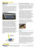
FIGURE 6.29
Leg par ts placement for
the robot’s left side.
FIGURE 6.30
Leg mechanism par ts
placement.
Amphibionics 06 3/24/03 9:02 AM Page 214
should be fastened with just enough pressure to allow the parts to
move freely without any resistance.
Cut six connector wires to a length of 6 inches each. Wire the
power switch, 9-volt battery strap, and three female header con-
nectors, as indicated in Figure 6.31. When the switch and con-
nectors are finished, mount the switch in the 1/4-inch hole in the
robot chassis with the switch mechanism facing down toward the
bottom of the robot, and the 9-volt battery strap facing toward the
back. Now that the mechanical and electrical systems are in place,
the next step is to add the electronics.
Chapter 6 / Crocobot: Build Your Own Robotic Crocodile
215
FIGURE 6.31
Power switch wiring
diagram.
Amphibionics 06 3/24/03 9:02 AM Page 215
The Controller Circuit Board
The robot’s main controller will integrate a PIC 16F84 microcon-
troller, a Lynx radio receiver module, and an L298 dual motor con-
troller chip all on a 1-1/2 inch by 2-1/2 inch circuit board. The
schematic for the controller board is shown in Figure 6.32.
The PIC 16F84 microcontroller is used to interpret the serial infor-
mation that is received from the Lynx radio receiver module, mon-
itor the leg limit switches, and control the motors via the L298
motor controller I.C. The 16F84 microcontroller is clocked at 4
MHz and operates from a 5-volt direct current (DC) supply that is
produced from a 78L05 voltage regulator, with the source being a
9-volt battery in the robot’s tail section. The motors operate from
their own 4.5-volt supply contained in the robot’s top cover. Six of
the PIC 16F84 port B pins will be connected to the L298 to control
the motors. The parts necessary to construct the main board are
listed in Table 6.2.
Amphibionics
216
FIGURE 6.32
Crocobot’s main
controller board.
Amphibionics 06 3/24/03 9:02 AM Page 216
Part Quantity Description
Semiconductors
U1 1 78L05 5V regulator
U2 1 PIC 16F84 flash microcontroller mounted
in socket
U3 1 L298 dual full-bridge driver
RX1 1 Lynx RXM-433-LC-S RF receiver module
D1 1 Red light-emitting diode
D2—D9 8 Diodes 1N4001
D10 1 Green light-emitting diode
Q1 1 2N3904 NPN transistor
Resistors
R1, R2 2 470 ⍀ 1/4-watt resistor
R3 1 10 K⍀ 1/4-watt resistor
R4 1 4.7 K⍀ 1/4-watt resistor
Capacitors
C1 1 0.1 µf
C2, C3 2 22 pf
C4, C5 2 .01 µf
Miscellaneous
JP1—JP4 4 2-post male header connector—2.5-mm
spacing
JP5—motors 1 4-post male header connector—2.5-mm
spacing
JP6—RF 1 4-post female header connector—2.5-mm
module spacing
(continued on next page)
Chapter 6 / Crocobot: Build Your Own Robotic Crocodile
217
TABLE 6.2
Parts List for
Crocobot’s Main
Controller Board
Amphibionics 06 3/24/03 9:02 AM Page 217
Part Quantity Description
Y1 1 4-MHz crystal
W1-W4 4 Jumper wire
Piezo buzzer 1 Standard piezoelectric element
I.C. socket 1 18-pin I.C. socket—soldered to PC board U2
Printed 1 See details in chapter.
circuit board
L298 Dual Full-Bridge Driver
This robot is a departure from the previous two robots detailed in
this book because it uses a twin DC motor gearbox as its source
of power, instead of RC servos. In order to safely control the
motors with the microcontroller, the L298 dual full-bridge driver
will be used, and is shown in Figure 6.33. The L298 is an inte-
grated monolithic circuit in a 15-lead multiwatt package. It is a
high-voltage, high-current dual full-bridge driver designed to
accept standard TTL logic levels and drive inductive loads such as
relays, solenoids, DC, and stepping motors. Two enable inputs are
provided to enable or disable the device independently of the input
signals. The emitters of the lower transistors of each bridge are
connected together, and the corresponding external terminal can
be used for the connection of an external sensing resistor. An addi-
tional supply input is provided so that the logic functions at a
lower voltage.
Amphibionics
218
TABLE 6.2
Parts List for
Crocobot’s Main
Controller Board
(continued)
Amphibionics 06 3/24/03 9:02 AM Page 218
How it works. The L298 contains two motor control circuits that
are referred to as the “H-Bridge.” This method of controlling DC
motors gets its name because the four transistors used to control
the motors are configured to form an “H” with the motor being at
the center. Figure 6.34 shows the basic schematic for a typical H-
Bridge. The H-Bridge works by having the control circuitry or
microcontroller turn on only two of the transistors at a time. In this
example, when transistors Q1 and Q4 are turned on, the motor will
spin in one direction. When transistors Q2 and Q3 are turned on,
the motor will spin in the opposite direction. When all of the tran-
sistors are turned off, the motor is stopped. Table 6.3 is a truth
table showing the state of each transistor and the motor direction.
Note that if transistors Q1 and Q3 (or Q2 and Q4) were turned on
at the same time, there would be a short circuit across the battery.
For this reason, the L298 has internal logic that prevents this from
happening.
Motor direction Q1 Q2 Q3 Q4
Stopped 0000
Forward 1001
Reverse 0110
Chapter 6 / Crocobot: Build Your Own Robotic Crocodile
219
FIGURE 6.33
L298 bidirectional
motor controller.
TABLE 6.3
H-Bridge Truth Table
Amphibionics 06 3/24/03 9:02 AM Page 219
With the L298, each bridge has three control inputs made up of an
enable line and two control lines. In our robot application, these
inputs will be controlled by the programmable interface controller
(PIC). The PIC will interpret the data received by the radio link and
then issue the proper motor commands, depending on the infor-
mation sent from the hand remote control. An external bridge of
diodes is required when inductive loads like DC motors are being
driven. The specifics of controlling the motors will be described
during the programming section.
Radio transmitter and receiver modules. The robot will be
remotely controlled using a pair of 433-MHz transmitter and
receiver modules. The modules that will be used are the TXLC-434
transmitter and the RXLC-434 receiver, available from Reynolds
Electronics at www.rentron.com. The modules are based around
Linx Technologies’ (www.linxtechnologies.com) LC series trans-
mitter modules. The staff at Reynolds Electronics have made using
Amphibionics
220
FIGURE 6.34
A typical H-Bridge DC
motor control
configuration.
Amphibionics 06 3/24/03 9:02 AM Page 220
these devices very easy by mounting the modules on small circuit
boards with connectors and a place to solder on the antennas
(which are included with the modules).
The LC Series is ideally suited for volume use in applications such
as remote control, security, identification, robotics, and periodic
data transfer. Packaged in a compact SMD package, the LC trans-
mitter utilizes a highly optimized SAW architecture to achieve an
unmatched blend of performance, size, efficiency, and cost. When
paired with a matching LC series receiver, a highly reliable wire-
less link is formed, capable of transferring serial data at distances
in excess of 300 feet. No external RF components, except an
antenna, are required, making design integration straightforward.
The features include: low cost, no external RF components
required, ultra-low power consumption, compact surface-mount
package, stable SAW–based architecture, support data rates to
5,000 bps, wide supply range (2.7-5.2 vdc), direct serial interface,
low harmonics, and no production tuning. The receiver module
pinout diagram is shown in Figure 6.35. Using the module to
receive information from the transmitter will be described when
programming is covered.
Chapter 6 / Crocobot: Build Your Own Robotic Crocodile
221
FIGURE 6.35
Receiver module pinout
diagram.
Amphibionics 06 3/24/03 9:02 AM Page 221
Creating the Main Controller
Printed Circuit Board
To fabricate the controller printed circuit board (PCB), photocopy
the artwork in Figure 6.36 onto a transparency. Make sure that
the photocopy is the exact size of the original. For convenience,
you can download the file from the author’s Web site, located at
www.thinkbotics.com, and simply print the file onto a transparen-
cy using a laser or ink-jet printer with a minimum resolution of
600 dpi. After the artwork has been successfully transferred to a
transparency, use the techniques outlined in Chapter 2 to create a
board. A 4-inch ϫ 6-inch presensitized positive copper board is
ideal. When you place the transparency on the copper board, it
should be oriented exactly the same as in Figure 6.36. It would be
a good idea to create the circuit board for the remote control at the
same time.
Amphibionics
222
FIGURE 6.36
Controller board PCB
foil pattern artwork.
Amphibionics 06 3/24/03 9:02 AM Page 222
Circuit board drilling and parts placement. Use a 1/32-inch
drill bit to drill all of the component holes on the PCB. Drill the
holes for the voltage regulator (U1) and the diodes (D2–D9) with
a 3/64-inch drill bit. Use Table 6.2 and Figure 6.37 to place the
parts on the component side of the circuit board. The PIC 16F84
microcontroller (U2) is mounted in an 18-pin I.C. socket. The 18-
pin socket is soldered to the PC board, and the PIC is inserted after
it has been programmed. Note that Figure 6.37 also shows four
jumper wires labeled W1–W4 that are not shown in the schemat-
ic. These jumpers were needed due to routing conflicts when
designing the PCB. Use a fine-toothed saw to cut the board along
the guide lines, and drill the mounting holes on the corners using
a 5/32-inch drill bit. Use 1/4-inch standoffs to mount the board.
Figure 6.38 shows the finished main controller board.
Chapter 6 / Crocobot: Build Your Own Robotic Crocodile
223
FIGURE 6.37
Controller board PCB
component side par ts
placement.
Amphibionics 06 3/24/03 9:02 AM Page 223
Check the finished board for any missed or cold soldered connec-
tions, and verify that all the components have been included. The
board will be tested later when programming the PIC microcon-
troller.
Adding the radio receiver module. Locate the radio receiver
module (RXLC-434) and flip it over so that the back is facing
upward. Solder the 7-inch antenna wire that was included with the
module to the tinned area on the board where there is no solder
mask. Figure 6.39 shows the antenna soldered to the board.
The next step is to bend all of the connector pins of the receiver
module on 90-degree angles toward the back of the module. Use
a pair of needle nose pliers to carefully bend each pin. This is
needed so that the module will sit parallel to the controller board
when it is plugged into its connector. Figure 6.40 illustrates how
Amphibionics
224
FIGURE 6.38
Parts soldered to the
finished PCB.
Amphibionics 06 3/24/03 9:02 AM Page 224
the pins should be bent. Once the pins have been bent, insert the
module into the 4-pin female connector (JP6) located in front of
the diode array. Orient the module so that it sits above the diodes
when it is plugged in. Figure 6.41 show the module plugged into
the circuit board.
Chapter 6 / Crocobot: Build Your Own Robotic Crocodile
225
FIGURE 6.39
Antenna soldered to the
receiver module PCB.
FIGURE 6.40
Receiver module
connector pins bent 90
degrees.
Amphibionics 06 3/24/03 9:02 AM Page 225
Putting It All Together
Now that the mechanical, electronics, and electrical systems are
all finished, it is time to integrate them all together into a working
robot. Start by mounting the circuit board to the chassis at the
head of the robot. Attach the robot’s tail section to the chassis with
a 6/32-inch ϫ 1/2-inch machine screw and locking nut. Tighten
the nut with enough torque to let the tail swing freely. Plug each
of the connectors into the main controller, as indicated in Figure
6.42. Note that the motor power supply battery pack can’t be
connected until the top cover has been attached to the chassis.
Place a new AA battery into each of the three battery holders
located on the top cover. Figure 6.43 shows the robot with the tail
section attached and all of the connecting wires plugged into the
controller board. Place a 9-volt battery into the battery clip locat-
ed in the tail section. Attach the battery strap to the battery. Feed
the antenna through the hole in the head section, then use three
6/32-inch ϫ 1/2-inch machine screws and nuts to attach the top
cover. Plug in the motor power connector before you fasten the
cover in place. Figure 6.44 shows the completed robot with the
Amphibionics
226
FIGURE 6.41
Receiver module
inserted into connector
on the main board.
Amphibionics 06 3/24/03 9:02 AM Page 226
Chapter 6 / Crocobot: Build Your Own Robotic Crocodile
227
FIGURE 6.42
Robot connection
diagram.
FIGURE 6.43
Robot with tail section
attached and all wiring
connected.
Amphibionics 06 3/24/03 9:02 AM Page 227
top cover attached. The PIC microcontroller will be programmed a
little later, during experimentation. Now that the robot is complete,
the remote control transmitter will be built.
Constructing the Remote
Control Transmitter
The remote control transmitter will be used to control the robot’s
movements and may be customized to control other devices as
well. The hand held remote control device uses an analog X and Y
axis control stick as the input to two analog-to-digital converters
residing on a PIC 16C71. The remote control is pictured in Figure
6.45.
Amphibionics
228
FIGURE 6.44
Completed robot with
cover attached.
Amphibionics 06 3/24/03 9:02 AM Page 228
The schematic for the transmitter remote control is shown in Figure
6.46. The circuit functions by using the PIC 16C71 to monitor the
position of the control stick and then send serial commands to the
transmitter module. When the control stick moves along the X and
Y axis, the resistance values of two 100K ⍀ potentiometers are var-
ied. The control stick and the two attached potentiometers are
shown in Figure 6.47. Each potentiometer is configured as a volt-
age divider so that a unique voltage represents each position along
the X- and Y-axis. The voltages from the potentiometers are con-
verted to 8-bit values by the internal analog to digital converters on
the PIC 16C71 and then interpreted by the microcontroller.
Depending on the values, certain movement commands are sent in
a serial format from the transmitter to the robot. The remote control
also has a programmable push-button switch and a light-emitting
diode (LED) that can be turned on when certain events occur, such
as during the transmission of a movement command. The transmit-
Chapter 6 / Crocobot: Build Your Own Robotic Crocodile
229
FIGURE 6.45
Robot remote control
device.
Amphibionics 06 3/24/03 9:02 AM Page 229
ter module is the TXLC-434 transmitter, available from Reynolds
Electronics at: www.rentron.com. The modules are based around
Linx Technologies’ (www.linxtechnologies.com) LC series transmit-
ter modules, as discussed earlier. The transmitter module pinout
diagram is shown in Figure 6.48. The only external part needed for
the module to function is a 430 ⍀ resistor that is connected from the
VADJ line to ground for 5-volt operation. If the resistor is not includ-
ed, then the device will operate at 3 volts. Using the module to
transmit information to the receiver will be discussed when pro-
gramming is covered.
Amphibionics
230
FIGURE 6.46
Remote control
schematic diagram.
Amphibionics 06 3/24/03 9:02 AM Page 230
Chapter 6 / Crocobot: Build Your Own Robotic Crocodile
231
FIGURE 6.47
Control stick with X and
Y axis potentiometers.
FIGURE 6.48
Transmitter module
pinout diagram.
Amphibionics 06 3/24/03 9:02 AM Page 231
PIC 16C71
The Microchip PIC 16C71 is very similar to the PIC 16F84 that has
been used throughout the book. The pinouts are identical. The dif-
ference is that the pins on PortA of the 16C71 can be configured to
take advantage of four on-chip analog-to-digital converters.
Another difference is that the chip is erased by exposure to ultra-
violet light. A small window on the top of the device allows light to
get at the chip. After the chip has been programmed, the window
should be covered with a sticker so that it does not get erased if it
is exposed to sunlight or fluorescent lighting. The 8-bit resolution
of the 4-channel high-speed 8-bit A/D is ideally suited for appli-
cations requiring a low-cost analog interface. Use of the A/D con-
verters will be discussed when the software routines are covered.
Although the 16C71 device was used in the book, Microchip now
manufactures an 18-pin, flash erasable device with analog-to-dig-
ital converters, identified as the PIC 16F818. Figure 6.49 shows
the PIC 16C71 with its ultraviolet erase window. The parts needed
to build the transmitter are listed in Table 6.4.
Amphibionics
232
FIGURE 6.49
Microchip PIC 16C71.
Amphibionics 06 3/24/03 9:02 AM Page 232
Part Quantity Description
Semiconductors
U1 1 78L05 5V regulator
U2 1 PIC 16C71 microcontroller mounted in
socket
TX1 1 Lynx TXM-433-LC-R RF transmitter module
D1 1 Red light-emitting diode
D2 1 Red light-emitting diode
Resistors
R1,R2,R6 3 470 ⍀ 1/4-watt resistor
R3 1 4.7 K⍀ 1/4-watt resistor
R4,R5 2 Control stick with two 100 K⍀
potentiometers
R7 1 1 K⍀ 1/4-watt resistor
Capacitors
C1 1 0.1 µf
C2,C3 2 22 pf
Miscellaneous
JP1 1 2-post male header connector—2.5-mm
spacing
JP2,JP6,JP7 3 2-post female header connector—2.5-mm
spacing
JP3 1 4-post female header connector—2.5-mm
spacing
JP4,JP5 2 3-post female header connector—2.5-mm
spacing
(continued on next page)
Chapter 6 / Crocobot: Build Your Own Robotic Crocodile
233
TABLE 6.4
List of Par ts Needed to
Build the Transmitter
Amphibionics 06 3/24/03 9:02 AM Page 233
Part Quantity Description
Y1 1 4-MHz crystal
I.C. socket 1 18-pin I.C. socket—soldered to PC board U2
Project box 1 3 inches wide x 1-1/2 inches deep
Battery strap 1 9-volt battery strap
S1—switch 1 SPST switch
S2—switch 1 Momentary contact—normally open
pushbutton
Antenna 1 6-3/4 inch whip antenna with threaded
mount
Enclosure connectors
JP1 1 2-post female header connector—2.5-mm
spacing
JP2,JP6,JP7 3 2-post male header connector—2.5-mm
spacing
JP3 1 4-post male header connector—2.5-mm
spacing
JP4,JP5 2 3-post male header connector—2.5-mm
spacing
Creating the Remote Control
Printed Circuit Board
To fabricate the PCB, photocopy the artwork in Figure 6.50 onto a
transparency. Make sure that the photocopy is the exact size of the
original. For convenience, you can download the file from the
author’s Web site, located at www.thinkbotics.com, and simply
print the file onto a transparency using a laser or ink-jet printer
with a minimum resolution of 600 dpi. After the artwork has been
Amphibionics
234
TABLE 6.4
List of Par ts Needed to
Build the Transmitter
(continued)
Amphibionics 06 3/24/03 9:02 AM Page 234
successfully transferred to a transparency, use the techniques out-
lined in Chapter 2 to create a board. A 4-inch ϫ 6-inch presensi-
tized positive copper board is ideal. When you place the trans-
parency on the copper board, it should be oriented so that it is
exactly the same as in Figure 6.50.
Circuit board drilling and parts placement. Use a 1/32-inch
drill bit to drill all of the component holes on the PCB. Drill the
holes for the voltage regulator (U1) with a 3/64-inch drill bit. Use
Table 6.4 and Figure 6.51 to place the parts on the component side
of the circuit board. Note that female sockets are used where cer-
tain components will be plugged in. This is to make it easier to
mount the control potentiometers, LEDs, and switches to the top
cover of the project box. The PIC 16C71 microcontroller (U2) is
mounted in an 18-pin I.C. socket. The 18-pin socket is soldered to
the PC board, and the PIC is inserted after it has been programmed.
Use a fine-toothed saw to cut the board along the guide lines.
Check the finished board for any missed or cold soldered connec-
tions, and verify that all the components have been included. The
board will be tested later when programming the PIC microcon-
troller.
Chapter 6 / Crocobot: Build Your Own Robotic Crocodile
235
FIGURE 6.50
Remote control PCB foil
pattern artwork.
Amphibionics 06 3/24/03 9:02 AM Page 235
Remote control project enclosure. Choose a project box that is
at least 3 inches wide, 5 inches in length, and 1-1/2 inches deep.
Depending on the control stick that you are using, the box may
need to be larger or smaller than the dimensions above. I used a
project box that had removable top and bottom panels to make it
easier to work with.
Locate the 6-3/4 inch whip antenna and cut the coaxial cable to a
length of 2-1/2 inches in length. Strip 1/2-inch of the shielding off
the end of the wire, and then strip the middle wire as well. Drill a
1/4-inch hole in the top, right side of the case, and mount the
antenna. Solder the antenna lead wire to the small area on the
back (the area without any solder mask) of the transmitter mod-
ule. Bend the connector pins of the transmitter module 90 degrees
downward. This is the same procedure that was performed on the
receiver module. Place the remote control circuit board in the case,
and then plug the transmitter module into the female connector
(JP3). Move the circuit to the top of the case, 1/2-inch from the
top. Use hot glue to secure the board in place. Figure 6.52 shows
the finished transmitter circuit board, with the antenna attached to
the case and the transmitter module.
Amphibionics
236
FIGURE 6.51
Remote control PCB
component side par ts
placement.
Amphibionics 06 3/24/03 9:02 AM Page 236
Mount the control stick, power switch, two LEDs, and push-but-
ton switch to the top cover of the project box in similar positions,
as shown in Figure 6.53. You will have to drill a 3/4-inch hole for
the control stick. Depending on the project box that you are using,
you may have to find the best positions for each of the compo-
nents. When the parts are mounted in the cover, use Figure 6.54
to wire the parts to the board. I used wires with a length of 3-1/2
inches to connect each component to the appropriate connector.
Figure 6.55 shows the components wired to the connectors. Once
the parts are wired to the connectors, attach a 9-volt battery, but
move the cover to the side to leave access to the 18-pin socket, so
that the PIC 16C71 can easily be inserted and removed during the
programming, debugging, and experimentation stages. We are
now ready to start programming the robot and transmitter.
Chapter 6 / Crocobot: Build Your Own Robotic Crocodile
237
FIGURE 6.52
Remote control circuit
board with antenna
connected.
Amphibionics 06 3/24/03 9:02 AM Page 237
Amphibionics
238
FIGURE 6.53
Mounting placement of
control stick, switches,
and light emitting
diodes.
FIGURE 6.54
Transmitter wiring
diagram.
Amphibionics 06 3/24/03 9:02 AM Page 238