Build Your Own Combat Robot phần 3 docx
Bạn đang xem bản rút gọn của tài liệu. Xem và tải ngay bản đầy đủ của tài liệu tại đây (877.41 KB, 40 trang )
UILDING a robot requires that you make many decisions—from the
type of sensors you’ll use to the color you’ll paint it. Some of these decisions are
trivial, while others will make or break your robot. One decision in the
make-or-break category is motors—not just deciding which ones you’ll use, but
determining how you’ll optimize their performance.
Most robots use the same class of motor—the permanent magnet direct current
(PMDC) motor. These commonly used motors are fairly low in cost and relatively
easy to control. Other types of electric motors are available, such as series-wound
field DC motors, stepper motors, and alternating current (AC) motors, but this
book will discuss only PMDC -type motors. If you want to learn more about other
types of motors, consult your local library or the Internet for that information.
Some combat robots use internal combustion motors, but they are more com-
monly used to power weapons than to drive the robots, largely because the inter-
nal combustion engine rotates only in one direction. If you are using an internal
combustion engine to drive the robot, your robot will require a transmission that
can switch into reverse or use a hydraulic motor drive system. With electric mo
-
tors, however, the direction of the robot can be reversed without a transmission.
Many combat robots combine the two, using electric motors for driving the robot
system and internal combustion motors for driving the weapons. Another use for
internal combustion engines is to drive a hydraulic pump that drives the robot
and/or operates the weapons.
Since most robots use PMDC motors, most of the discussion in this chapter
will be focused on electric motors. At the end of this chapter is a short discussion
of internal combustion engines.
E
lectric Motor Basics
Because the robot’s speed, pushing capability, and power requirements are di
-
rectly related to the motor performance, one of the most important things to un
-
derstand as you design your new robot is how the motors will perform. In most
robot designs, the motors place the greatest constraints on the design.
62
Direct current (DC) motors have two unique characteristics: the motor speed is
proportional to the voltage applied to the motor, and the output torque (that is,
the force producing rotation) from the motor is proportional to the amount of
current the motor is drawing from the batteries. In other words, the more voltage
you supply to the motor, the faster it will go; and the more torque you apply to the
motor, the more current it will draw.
Equations 1 and 2 show these simple relationships:
The units of K
v
are RPM per volt and K
t
are oz in. per amp (or in lb. per amp).
Torque is in oz in. and RPM is revolutions per minute. K
v
is known as the motor-
speed constant, and K
t
is known as the motor-torque constant.
These equations apply to the “ideal” motor. In reality, certain inefficiencies exist
in all motors that alter these relationships. Equation 1 shows that the motor speed
is not affected by the applied torque on the motor. But we all know through expe-
rience that the motor speed is affected by the applied motor torque—that is, they
slow down. All motors have a unique amount of internal resistance that results in
a voltage loss inside the motor. Thus, the net voltage the motor sees from the bat-
teries is proportionally reduced by the current flowing through the motor.
Equation 3 shows the effective voltage that the motor actually uses. Equation 4
shows the effective motor speed.
Where V
in
is the battery voltage in volts, I
in
is the current draw from the motor in
amps, R is the internal resistance of the motor in ohms, and V
motor
is the effective mo
-
tor voltage in volts. It can easily be seen in Equation 4 that as the current increases
(by increasing the applied torque), the net voltage decreases, thus decreasing the
motor speed. But speed is still proportional to the applied voltage to the motor.
With all motors, a minimum amount of energy is needed just to get the motor to
start turning. This energy has to overcome several internal “frictional” losses. A
minimum amount of current is required to start the motor turning. Once this
threshold is reached, the motor starts spinning and it will rapidly jump up to
the maximum speed based on the applied voltage. When nothing is attached to the
output shaft, this condition is known as the no-load speed and this current is
known as the no-load current. Equation 5 shows the actual torque as a function of
the current draw, where I
0
is the no-load current in amps. Note that the motor de
-
livers no torque at the no-load condition. Another interesting thing to note here is
Chapter 4: Motor Selection and Performance 63
4.1
4.2
4.3
rpm K V K (V I R)==−
in in
motor
vv
4.4
64 Build Your Own Combat Robot
that by looking at Equation 4, the voltage must also exceed the no-load current
multiplied by the internal resistance for the motor to start turning.
Some motors advertise their no-load speed and not their no-load current. If the
motor’s specifications list the internal resistance of the motor, the no-load current
can be determined from equation 4.
With these equations, as well as the gear ratio, wheel size, and coefficient of
friction between wheels and floor,you can determine how fast the robot will move
and how much pushing force the robot will have. (How you actually determine
this will be explained in Chapter 6.) If you want the robot to go faster, you can ei
-
ther run the motors at a higher voltage or choose a lower gear reduction in the
drive system.
Equation 5 is an important equation to know and understand, because it will
have a direct effect on the type and size of the batteries that you will need. By rear
-
ranging this equation, the current draw requirements from your batteries can be
determined. Equation 6 shows this new relationship.
For any given torque or pushing force, the battery current requirements can be
calculated. For worst-case situations, stalling the motors will draw the maximum
current from the batteries. Equation 7 shows how to calculate the stall current,
where I
stall
is the stall current in amps. The batteries should be sized to be able to de-
liver this amount of current. Batteries that deliver less current will still work, but
you won’t get the full performance potential of the motors. Some builders pur
-
posely undersize the battery to limit the current and help the motors and electron
-
ics survive, and others do this simply because they have run out of weight
allowance. For some motors, the stall current can be several hundreds of amps.
Another set of relationships that needs to be considered is the overall power being
supplied by the batteries and generated by the motor. The input power, P
in
,tothe
motor is shown in equation 8. Note that it is highly dependent on the current draw
from the motor. The output power, P
out
, is shown in mechanical form in equation 9
and in electrical from in equation 10. Motor efficiency is shown in equation 11.
The standard unit of power is watts.
4.5
4.6
4.7
4.8
4.9
4.10
The output power is always less than the input power. The difference between
the two is the amount of heat that will be generated due to electrical and frictional
losses. It is best to design and operate your robot in the highest efficiency range to
minimize the motor heating. If the motor is able to handle the heat build-up, it
might be best to design the robot (or weapon) to be operated at a higher percent
-
age of the motor’s maximum power (to keep the motor as light as possible). For
example, a motor that is used to recharge a spring-type weapon might be fine if
operated at near-stall load for just a few seconds at a time. The maximum amount
of heat is generated when the motor is stalled. A motor can tolerate this kind of
heat for short periods of time only, and it will become permanently damaged if it’s
stalled for too long a period of time. This heat is generated in the armature wind
-
ings and the brushes, components that are hard to cool by conduction.
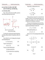
Figure 4-1 shows a typical motor performance chart. These charts are usually
obtained from the motor manufacturer, or a similar chart can be created if you
know the motor constants. The motor shown in Figure 4-1 is an 18-volt Johnson
Electric motor model HC785LP-C07/8, which can be found in some cordless
drills. The constants for this motor are shown in Table 4-1. This motor is dis-
cussed here as an example motor to describe how all of the motor constants relate
to each other and how they affect the motor performance.
Figure 4-1 graphically displays how the motor speed decreases as the motor
torque increases and how the motor current increases as the applied torque on the
motor increases. For this particular motor, maximum efficiency is approximately
Chapter 4: Motor Selection and Performance 65
4.11
FIGURE 4-1
Typical motor
performance
curves.
75 percent and it occurs when the motor is spinning at approximately 19,000 RPM.
Maximum output power from this motor occurs when the motor speed decreases to
about 50 percent of its maximum speed and the current is approximately 50 percent
of the stall current. For all permanent magnet motors, maximum power occurs
when 50 percent of the stall current is reached. Motor manufacturers recommend
that motors be run at maximum efficiency; otherwise, motors will overheat faster.
66 Build Your Own Combat Robot
I
0
1.934 amps
R 0.174 ohms
K
v
1,234.6 rpm/volt
K
t
1.097 oz-in/amp
TABLE 4-1 Motor Constants for Figure 4-1
n
True Story: Grant Imahara and Deadblow
Grant Imahara started his career in robotics as a kid by drawing pictures of robots
from movies and television. Later, his designs evolved into LEGOs, and then cardboard
and wood. “Only recently,” he laments, “have I had the tools and equipment to build
them out of metal.”
Though Grant got his start as part the Industrial Light and Magic team at Robot
Wars in 1996 (he’s an animatronics engineer and model maker for George Lucas’
ILM special effects company), he is perhaps best known for his creation known as
Deadblow.
Deadblow is a robot with its share of stories. “The best match I ever fought was
against Pressure Drop in season 1.0,” Grant recalls. “I had broken the end of my
hammer off in a previous match against a robot named Alien Gladiator.”
Grant had a spare arm, but, not really expecting to need it, he hadn’t fully
prepared it to mate with the robot. Without the hammer head, he had no weapon,
so a little quick construction work was called for. “‘No problem,’ I thought. I’ll just
drive back to ILM and work on it at our shop. With three hours before the next
match, I figured it would be a breeze.”
Unfortunately, Grant soon uncovered a glitch. “We drove up to the shop and I
started working on the hammer arm. I discovered to my horror that we were out of
carbide mills, and I had to put two holes in case-hardened steel. After going through
several high-speed steel bits and getting nowhere, I resorted to going through my
co-worker’s desks, trying to find a carbide tool. Finally, I found a tiny 1/16-inch carbide
bit. I took this bit and chucked it into a Dremel tool and painstakingly bored two
3/8-inch holes in the handle of my hammer by hand.”
Chapter 4: Motor Selection and Performance 67
Determining the Motor Constants
To use the equations, the motor constants, K
v
, K
t
, I
0
, and R must be known. The
best way to determine the motor constants is to obtain them directly from the motor
manufacturer. But since some of us get our motors from surplus stores or pull
them out of some other motorized contraption, these constants are usually un-
known. Fortunately, this is not a showstopper, because these values can be easily
measured through a few experiments.
You’ll need a voltmeter and a tachometer before you start. To determine the
motor speed constant, K
v
, run the motor at a constant speed of a few thousand
RPMs. Measure the voltage and the motor speed, and record these values. Repeat
the test with the motor running a different speed, and record the second values.
The motor speed constant is determined by dividing the measured difference in the
motor speeds and the difference between the two measured voltages:
All permanent magnet DC motors have this physical property, wherein the
product of the motor speed constant and the motor torque constant is 1352. With
this knowledge, the motor torque constant can be calculated by dividing the motor
speed constant by 1352. The units for this constant is (RPM / Volts) × (oz in. / amps).
Equation 13 shows this relationship.
The next step is to measure the internal resistance. This cannot be done using
only an ohmmeter—it must be calculated. Clamp the motor and output shaft so
that they will not spin. (Remember that large motors can generate a lot of torque
and draw a lot of current, so you need to make sure your clamps will be strong
Grant Imahara and Deadblow (continued)
With only an hour left and a 20-minute drive to get back to the competition,
Grant still wasn’t overly concerned. “But then we hit Sunday evening traffic back
into San Francisco. We were going to be late. Forty-five minutes later, I ran into
Fort Mason with the new hammer in hand. And we threw it into the robot.” As the
announcer called Team Deadblow to line up for the fight, they were still screwing
the armor back onto the robot. “If you look carefully,” Grant says, “you can see that
my normally put-together look had become severely disheveled. I was out of breath
and about to pass out and the match hadn’t even started yet! I had a ‘go for broke’
attitude for that match, and the adrenaline was pumping. Deadblow went in and
pummeled Pressure Drop with a record number of hits. By the end, I could barely
feel my hands because they were tingling so much.”
4.12
4.13
enough to hold the output shaft still.) Apply a very low DC voltage to the motor—a
much lower voltage than what the motor will be run at. If you do not have a variable
regulated DC power supply, one or two D-cell alkaline batteries should work.
Now measure both the voltage and current going through the motor at the
same time. The best accuracy occurs when you are measuring several hundred
milliamps to several amps. The internal resistance, R, can be calculated by divid
-
ing the measured voltage, V
in
, by the measured current, I
in
:
It is best to take a few measurements and average the results.
To determine the no-load current, run the motor at its nominal operating volt
-
age (remember to release the output shaft from the clamps, and have nothing else
attached to the shaft). Then measure the current going to the motor. This is the
no-load current. The ideal way to do this is to use a variable DC power supply. In
-
crease the voltage until the current remains relatively constant. At this point, you
have the no-load current value. The no-load current value you use should be the
actual value for the motor running at the voltage you intend to use in your robot.
After conducting these experiments, you will now have all of the motor con-
stant parameters to calculate how the motor will perform in your robot.
Power and Heat
When selecting a motor, you should first have a good idea of how much power
that your robot will require. A motor’s power is rated in either watts or horse-
power (746 watts equal 1 horsepower). Small fractional horsepower motors of
the type that are usually found in many toys are fine for a line-following or a
cat-annoying robot. But, if your plan is to dominate the heavyweight class at
BattleBots, you will require heavyweight motors. This larger class of motors can
be as much as 1,000 times more powerful than the smaller motors.
A small toy motor might operate at 3 volts and draw at most 2 amps, for an input
requirement of 6 watts (volts × amps = watts). If the motor is 50-percent efficient,
it will produce 3 watts of power. At the other end of the spectrum are the robot
combat class motors. One of these might operate at 24 or 48 volts and draw hundreds
of amps, for a peak power output of perhaps 5 horsepower (3,700 watts) or more.
Two of these motors can accelerate a 200-pound robot warrior to 15-plus mph in
just a few feet, with tires screaming. One 1997 heavyweight (Kill-O-Amp) had
motors that could extract 1,000 amps from its high-output batteries! The power
that your robot will require is probably somewhere between these two extremes.
Your bot’s power requirements are affected by factors like operating surface. For
example, much more power is required to roll on sand than on a hard surface.
Likewise, going uphill will increase your machine’s power needs. Soft tires that
you might use for greater friction have more rolling resistance than hard tires,
68 Build Your Own Combat Robot
4.14
which will increase the power requirements. Do you have an efficient drive train,
or are you using power-robbing worm gears? How fast do you want to go?
An internal combustion engine produces its peak horsepower at about 90 per
-
cent of its maximum RPM, and peak torque is produced at about 50 percent of
maximum RPM. The higher the RPM, the more energy it consumes. Compare this
to the PMDC motor, which consumes the most energy and develops its peak
torque at zero RPM. It consumes little energy at maximum RPM, and it produces
its peak horsepower at 50 percent of its unloaded speed.
At 50 percent of maximum speed, the PMDC motor will draw half of its maxi
-
mum stalled current, as seen earlier in Figure 4-1. Unfortunately, much of the cur
-
rent going into the motor at this high power level is turned into heat. Figure 4-2
shows how much heat is generated in the example motor used to create the statis
-
tics in Figure 4-1.
It is obvious to see that the minimum amount of heating occurs when running
the motor near its maximum speed and efficiency. It can also be seen in Figure 4-2
that as the motor torque increases, a near exponential increase in motor heat re
-
sults. Motors can tolerate this amount of heat only for short periods of time. Con-
tinuously running a motor above the maximum power output level will seriously
damage or destroy it, depending on how conservatively the manufacturer rated
the motor.
Many motors are rated to operate continuously at a certain voltage. You can
increase the power of your motor by increasing the voltage. Figure 4-3 shows how
a motor’s speed, torque, and current draw are affected by increasing the input
voltage to the motor. In Figure 4-3, you can see that the motor speed is doubled
Chapter 4: Motor Selection and Performance 69
FIGURE 4-2
Heat generated in
an electric motor.
and the maximum stall torque is doubled when the input voltage is doubled. Re-
call from equation 4 that the motor’s speed is proportional to the applied voltage.
In Figure 4-3, you will notice that the current draw line from the 18-volt and
36-volt cases are on top of one another. Remember that the current draw is only a
function of the applied torque on the motors, and it is not related to the voltage. So
for a fixed torque on the motor, the current draw will be the same regardless of the
speed of the motor.
Figure 4-4 shows how the output power from the motor is affected by doubling
the applied voltage. You can see that increasing the voltage can significantly in
-
crease the output power of the motor. The maximum power at 36 volts is approxi
-
mately four times greater than the maximum power at 18 volts. The maximum
power of this 18-volt motor is 448 watts, or 0.6 horsepower. By doubling the voltage,
this motor has become a 2.5-horsepower brute! Not only does the power increase,
so does the motor’s efficiency. The maximum efficiency of the motor at 18 volts is
74.5 percent, and at 36 volts the maximum efficiency is 81.6 percent—a 7 percent
increase in efficiency just by doubling the voltage!
A big factor in choosing a motor is the conditions under which it will operate.
Will the motor run continuously, or will it have a short duty cycle? A motor can be
pushed much harder if it is used for a short time and then allowed to cool. In fact,
heat is probably the biggest enemy of the PMDC motor.
By doubling the motor’s voltage, you can double the top speed of the robot, and
you can even double the stall torque of the motor. But be forewarned: These im
-
provements do not come without a cost. Figure 4-5 shows the heat generated in
the motors as the applied torque increases. Doubling the voltage, and therefore
70 Build Your Own Combat Robot
FIGURE 4-3
Motor speed and
torque changes
by doubling the
input voltage.
the current, increases the heat by a factor of four! Stalling the motor will cause the
motors to overheat and be seriously damaged in a short period of time. Nothing is
free in the world of physics.
Chapter 4: Motor Selection and Performance 71
FIGURE 4-4
Motor power
changes by doubling
the input voltage.
FIGURE 4-5
Heat generated
by doubling the
applied voltage.
72 Build Your Own Combat Robot
Heat can destroy a motor in several ways. Most lower-cost PMDC motors use
ferrite magnets, which can become permanently demagnetized if they are over
-
heated. They can also be demagnetized by the magnetic fields produced when the
motor is running at a voltage higher than that at which it is rated. The flexible
braided copper leads that feed current to the brushes (called shunts) can melt after
just a few seconds of severe over-current demands. The insulation on the heavy
copper windings can fail, or the windings can even melt. Depending on the motor
brush mounting technique used, the springs used to keep the brushes on the com
-
mutator can heat up and lose their strength, thus causing the brushes to press less
tightly against the commutator. When this happens, the brushes can arc more,
heat up, and finally disintegrate. You don’t want to use that expensive motor as a
fuse, so make sure it can handle the heat.
Motor heating is proportional to the current
2
× resistance. Our 18-volt motor
example has a resistance of 0.174 ohms. If you were to stall it, it would draw
103 amps. If you stalled the same motor at 36 volts, it would draw 207 amps.
Since heating is a function of current
2
, the motor would get four times as hot.
Pushing 207 amps through a resistance of .174 ohms will generate 7,455 watts of
heat, which is five times more than the heating output of a typical home electric
space heater. Now imagine all the power of your portable heater multiplied by five
and concentrated into a lump of metal that weighs just a few pounds. You can see
why survival time is limited.
The physical size of the motor that would best fit your robotic needs is in large
part determined by the amount of heat that will be generated. Some people find it
surprising that a 12-ounce motor can produce exactly the same amount of power
as a 5-pound motor. The same formula for motor power is just as true for small
motors as it is for large motors. The difference is in how long that power can be
produced. The larger motor has a larger thermal mass, and can therefore absorb a
lot more heat energy for a given temperature rise.
Pushing the Limits
Okay, so you would like to use a greater-than-recommended voltage on your motor
to get more power out of it, but you are worried about damaging it. What should
you do? First, you must realize that you always run the risk of destroying your motor
if you choose to boost its performance past the manufacturer’s specifications. Fol
-
lowing are some things you can do to minimize the risk.
Limit the duty cycle. If you run your motor for, say, 1 minute on and 5 minutes
off, it should survive. Cooling is critical for an overdriven motor. One Robot Wars
heavyweight (La Machine) cooled its over-volted motors by directing the output
of a ducted fan into them. This ducted fan was originally created for use in propul
-
sion in model airplanes because they put out a lot of air.
An easier way to accomplish this same effect is to use batteries that are limited in
the amount of current that they can produce. The problem here, though, is that you
will often be pushing your battery to output levels that will shorten its useful life.
Even the sealed lead-acid batteries can sometimes boil and leak under heavy loads.
Chapter 4: Motor Selection and Performance 73
Another method that can be used to help control the heat buildup in the motors is
to use an electronic speed controller (ESC). The ESC is a device that meters the flow
of current to your motor. It does this by rapidly switching the current on and off,
several hundred to several thousand times per second. One way in which controllers
from different companies differ is in the frequency at which they chop the current
to the motor. The motor takes a time average of the amount of time the current is
on versus the time between each cycle. As a result, the motor will see a lower “av
-
erage” current and voltage than it would if it were on continuously. Hence, the
motors will see less heating.
As stated before, nothing happens for free in the world of physics. Electronic
controllers get hot and require heat sinking. They also can generate radio fre
-
quency interference, which might cause problems in a radio-controlled robot.
Chapter 7 will provide a more detailed discussion on electronic speed controllers.
High-Performance Motors
If you are still not satisfied with the performance of your motor (and money is no
object), you might want to purchase a high-performance motor. High-perfor-
mance motors have one major difference (and several minor ones) from regular
motors—in a word, efficiency. We have been discussing motors with 50- to
75-percent efficiencies. That is the range for fair to very good ferrite magnet mo-
tors. When we step up to rare-earth magnets, we get into a whole new realm of
performance. The efficiency figures for small rare-earth magnet motors range
from about 80 to 90 percent.
Rare-earth magnets are made from either cobalt or neodymium alloys. The
magnetic fields are so powerful that they are actually dangerous to handle. A mo-
ment’s inattention may result in a nasty crush as your finger is caught between
them and a stray piece of metal. The added bonus with cobalt alloy magnets is that
they are resistant to demagnetization, no matter how much voltage you pump into
it or how hot it gets. Motors with rare-earth magnets run much cooler than ferrite
motors. While running under ideal operating conditions, a ferrite motor turns
about 33 percent of the power it consumes into heat, whereas the rare-earth motor
wastes only about 10 to 20 percent of the electricity you feed it.
Another class of high-performance motor is the brushless PMDC motor.
The brushes in an ordinary motor can be the source of several problems: they
spark and cause radio interference, they are a source of friction, and they wear
out. The brushless motors have sensors that detect the position of the rotor rel
-
ative to the windings. This information is sent thousands of times a second to a
special controller that energizes the windings at the optimum moment on each
revolution of the motor. In a brushless motor, the windings are stationary and
the magnets spin—exactly the opposite of a conventional motor. This configu
-
ration is capable of much higher speeds. You can get motors that spin at
50,000 RPM or more. The major drawback to the high-performance motors is
that they are significantly more expensive then regular motors.
Motor Sources
You can acquire electric motors in two ways: you can purchase them from a motor
manufacturer or retail store, or you can salvage them from other pieces of equip
-
ment. Many robot builders use salvaged motors because they usually cost less
than 20 percent of the original cost of buying a brand new motor. Appendix B in
this book lists sources for obtaining robot motors.
Robotics companies are starting to sell motors that are specifically designed for
combat robots. For example the 3.9-horsepower Magmotor sold by http://
www.RobotBooks.com has become the standard motor used in several champion
BattleBots. Figure 4-6 shows a photograph of the motor.
Because electric motors are so common, they can be found easily. Some of the
best places to get good electric motors are from electric bicycles, electric scooters
and mopeds, electric children’s cars where the kids ride and drive, electric model
cars and planes, trolling motors, windshield wiper motors, power window mo
-
tors, power door locks, and even powered automobile seat motors can be used.
Some people have even used automotive and motorcycle starter motors and elec-
tric winches from the front of a pickup truck or from a boat trailer.
Probably the two best places to get electric motors are from electric wheel-
chairs and high-powered cordless drill/drivers. The advantages to the electric
wheelchair motors are that they already come with a high-quality gearbox, and
the output shaft has a good set of support bearings. Depending on which type of
motor you get, you could directly attach the wheels of the robot to the output
shaft of these motors. Several companies sell refurbished wheelchair motors. One
of the best places to get these motors is from National Power Chair (http:// www.
npcinc.com). Figure 4-7 shows a wheelchair motor.
74 Build Your Own Combat Robot
FIGURE 4-6
24-volt,
3.9-horsepower
electric motor.
(courtesy of Carlo
Bertocchini)
Chapter 4: Motor Selection and Performance 75
Cordless drill motors are excellent motors for driving small- to medium-sized
robots. Some heavyweight robots have successfully used cordless drill motors,
which are small and compact, and can deliver a lot of torque and speed for their
size by using planetary gears. One of the other advantages to using cordless drill
motors is that they already come with a set of high-capacity batteries and battery
chargers. This almost becomes an all-in-one package for building combat robots.
The drawbacks to using cordless drill motors are that there is no simple way to
mount the motors in the robot; they don’t have output shaft bearings to support
side loads; and the output shaft is threaded, which makes it difficult to attach any-
thing to it. The best way to use them is to make a coupling and pin it directly to the
threaded output shaft. The coupling then attaches directly to a bearing-supported
shaft or axle. Figure 4-8 shows the electric motor, gearbox, and clutch from a
Bosch 18-volt cordless drill reconfigured into a robot gearbox to drive two sprockets.
FIGURE 4-7
24-volt, 185 rpm,
896 in-lb.
stall torque
wheelchair motor.
(courtesy of
National Power
Chair)
FIGURE 4-8
Bosch 18-volt
cordless drill motor
converted into a
robot drive motor.
I
nternal Combustion Engines
Not all robots use electric motors to drive and power the weapons. Some robots
use internal combustion engines to perform this important task. These engines are
much smaller than those found in automobiles and are usually obtained from gas
-
oline-powered lawnmowers, rototillers, or even weed whackers. The energy density
of gasoline is about 100 times greater than that of batteries, and this makes gasoline
an attractive source for powering large combat robots. Conversely, gasoline is also
the main factor in not selecting this method of power—it is flammable and dan
-
gerous. Figure 4-9 shows a 119 cc air-cooled, two-cycle, gasoline-powered cut-off
saw by Partner Industrial Products. This saw, equipped with a 14-inch diameter saw
blade, was used as the primary weapon in Coolrobots super heavyweight cham
-
pion Minion.
Because most combat robots use electric motors, this book will not go into de
-
tails of how to use internal combustion engines in combat robots. By reading the
rules and regulations of the BattleBots competition, you will get a good under
-
standing of what is allowed and not allowed with gasoline engines. The key ele-
ments for a gasoline-powered robot is to be able to control the engine if it is upside
down, making sure that the fuel does not leak and that fuel flow remains constant
in the rough jarring environment, and that you can throttle the speed up and down
as you need to. A lot of the gasoline safety and performance schematics will be
similar to those of high-powered gasoline-powered model aircraft. Good candi-
date gasoline engines for combat robots are chainsaw engines, because they have a
carburetor that can operate in all positions.
Since internal combustion engines operate in one direction only, a transmission
that has a reverse gear must be used if the gas-powered engines are used to drive
76 Build Your Own Combat Robot
FIGURE 4-9
K1250 14-inch,
119 cc gasoline-
powered engine
prior to being used
as a weapon
system in Minion.
(courtesy of
Christian
Carlberg)
the robot. If the engine is used to drive a hydraulic pump, the pump needs to have a
solenoid valve to reverse the direction of the hydraulic fluid. Probably the most
common use for gasoline engines is to power spinning weapons because these
weapons spin in only one direction.
For more information on how to use an internal combustion engine in a combat
robot, talk with other robot builders that have used them and read up on how to
use large engines in model aircraft.
C
onclusion
The motors are the muscles of your robot. By understanding how the motors work
and how to push them to their limits, you will be able to determine the appropriate
motors, the types of batteries, and the appropriate-sized electronic speed control
-
lers for your robot. When building your combat robot, the motors are usually the
first major component that is selected. Sometimes the motors are selected based
on performance goals, and other times the robots are built around a set of motors
that you already have. Both are acceptable ways to build competitive combat robots.
Understanding how current works in the motors will help you determine what
type of battery you will need. Chapter 5 will cover how to determine the appropriate
size of battery you will need for a robot. Understanding how fast a motor turns
and how much torque the motors can generate will help you determine what type
of speed reduction/transmission the robot will need to meet your desired goals.
Chapter 6 covers this topic. By understanding how the voltage and current relate
to one another, determining the right type of speed controller can be accom-
plished. Chapter 7 will discuss how to select the appropriate-sized electronic
speed controller. Understanding how heat can destroy the motors will help you
avoid accidental meltdowns.
Before selecting a motor, you should understand how the subjects presented in
Chapters 3 through 7 relate to one another. Now, this isn’t required—in fact,
many robot builders simply pick a motor and build a robot around it. If they’re
lucky, everything works out just fine. However, most robot builders learn the
hard way, as things break because they inadvertently pushed components past
their capabilities. How you choose to build your robot is totally up to you.
Chapter 4: Motor Selection and Performance 77
5
It’s All About Power
Copyright 2002 by The McGraw-Hill Companies, Inc. Click Here for Terms of Use.
80
LECTRICALLY powered competition robots are quite demanding on
their batteries, which must weigh as little as possible yet supply a lot of current.
such requirements push the batteries to their limits. the high current demands can
have some surprising results on battery performance, and you need to consider
this when selecting the type of battery to use.
This chapter discusses how to determine battery requirements, how these re-
quirements affect battery performance, and how to estimate battery life. At the
end of this chapter is a discussion on the various pros and cons of different battery
types that can be used in combat robots. Understanding how well the batteries
perform is crucial to your ability to build a winning competition robot.
B
attery Power Requirements
The batteries’ primary purpose is to keep your robot powered during the competi-
tion. These competitions can last up to 5 minutes, so the battery must supply all the
power to the robot during that time. Selecting an appropriately sized battery that
will confidently run your robot throughout the entire match can be a significant
competitive advantage. The lightest battery will allow the robot to use the weight
savings for other things, such as weapons and armor. A properly selected battery
will have enough capacity to supply full running current continuously to your ro
-
bot’s motors; and it will be able to supply the peak currents that will allow your
robot’s motors to deliver the maximum torque, when needed.
Measuring Current Draw from the Battery
You can find out from the motor specification sheets exactly what current draw to
expect when running the motor. Adding up all the currents from the various mo
-
tors on your robot will tell you the maximum and typical motor running currents
to expect.
Because many of us use motors that come without data sheets, we have to mea
-
sure the running currents ourselves. To do this, you need to have a good battery
Chapter 5: It’s All About Power 81
from which to draw the current. You might ask yourself, “Do I really need to buy a
battery to test what size battery I need?” Yes, you do, if you want to be able to mea
-
sure the current draw. The battery voltage of this test battery must not droop while
testing for the current draw. In other words, the voltage must remain constant
throughout the tests. The advantage of using a large lead acid battery for the current
draw tests is that, because it will provide a long run time, you can use this battery
during the initial testing phases of the robot. After you have selected the appropriate
batteries for your robot, you can use them for all of the final test phases.
In most cases, fighting robots will draw a lot of current—much more than the
maximum current rating of most multimeters. The best tool to use to measure the
current draw is a high-current ammeter capable of measuring more that 100 amps.
Using Ohm’s Law to Measure Current Draw
You can also measure the resistance of the motor and calculate the current draw
from this measurement using Ohm’s Law. The formula to do this is current = volt
-
age / resistance. This formula doesn’t necessarily provide a reliable measure, however,
because, first, the resistances are very low for competition motors and most ohm
meters are not accurate at such low resistance levels. Second, if this measurement
is made accurately, it must be made considering the resistances of the complete
wiring harness, motor drivers, and motor. Last, even if the measurement is done
accurately, the calculated current will be much higher than actual due to frictional
and heat losses.
In all fairness, if measured accurately, the peak motor currents can be deter-
mined using an ohm meter and this formula:
Here, the current, I, is in amps; the voltage, V, is in volts; and the resistance, R,
is in ohms. To use this method, place a high-power, small-resistance-value resistor
in series with your robot’s battery supply. Then, using a voltmeter, measure the
voltage across this resistor.
Suitable Resistor and Measurement Basics
If you have access to a low-value, high-wattage resistor, you should use it to per
-
form your measurements—but resistance, high-wattage resistors are hard to find.
The resistance should be less than 0.01 ohms. If your motor’s expected peak cur
-
rent draw is 100 amps, you will need at least a 100-watt resistor. If you don’t have
access to such a resistor, a 0.01-ohm resistor can be made with 6.2 feet of readily
available #12 copper wire. The wire needs to be slightly longer than 6.2 feet, but
you can connect the voltmeter at the place on the wire that is 6.2 feet from the bat
-
tery. In addition, it is a good idea to keep the insulation on the wire and to coil up
5.1
82 Build Your Own Combat Robot
the wire so that it is easy to handle. Temperature causes the resistance to change,
so use the wire at room temperature and don’t use it so long that it heats up.
1. Place the resistor in series with your robot’s battery.
2. Measure the voltage across the resistor (a 6.2-foot-long coil of #12 wire,
or the high-wattage resistor) with the robot running in normal battle-like
conditions. When measuring this voltage, the value will likely be variable
and may appear unstable. Take the maximum reading, and then take
a reading that appears to be the nominal or average value. The robot’s
motors must be loaded to simulate those of a real battle, or else you will
measure a value that is much too low—up to five to ten times too low
than battle-use values.
3. When you have gathered these voltage values, calculate the current by
placing the voltage readings into the formula current = voltage / 0.01 ohms.
The 0.01 ohms is the resistance of the 6.2-foot-long wire. If you are using
a high-wattage resistor, then substitute the 0.01 ohms for the resistance
of your resistor. For example, suppose that when running the experiment,
you noted a maximum voltage of 1.2 volts and an average of 0.5 volts.
Plugging these values into the formula yields a maximum current value
of 120 amps (120 amps = 1.2 volts / 0.01 ohms) and a typical current of
50 amps (50 amps = 0.5 volts / 0.01 ohms). After you have found the
maximum current value and the typical current value, you have the
information that you need to choose the correct battery for your robot.
Blowing Fuses on Purpose?
An alternative method for measuring current draw is one of the easiest methods
and is fairly accurate. You can use the fuse holder that is in-line with your robot’s
battery to measure draw. Fuses are commonly used for testing, but few people use
fuses during an actual competition. It is usually better to risk an electrical fire than
to blow a fuse and be a sitting duck for your opponent to destroy your bot with
impunity. A blown fuse in battle also means an automatic loss!
To use this method, you’ll need a handful of fuses of various amperages. Start
with a fast blow fuse, and select values that you think it will survive. Install this
fuse and test run your robot in battle-like conditions.
note It is important that you test your robot in battle-like conditions, or else the
measurement will yield a current draw that is lower than what will occur in the robot arena.
Keep changing the fuse values until you find the fuse value that will survive and
the highest fuse value that fails. Between these two values is your robot’s maximum
current draw. Using this method, you can find the maximum running current of
your robot to within 5 amps. Next, switch to slow-blow fuses. You want to find
the fuse that lasts for about 1 minute while running your robot in battle-like con
-
ditions. This fuse value will yield your typical running current.
After you have found the maximum current value and the typical current value,
you have the information that you need to size your battery.
B
attery Capacity Basics
Batteries come in several varieties:
■ Sealed Lead Acid (SLA)
■ Nickel Cadmium (NiCad)
■
Nickel Metal Hydride (NiMH)
■
Alkaline
■
Lithium Ion
Each of these will be discussed later in the chapter in the section “Battery Types.”
The amp-hour (Ahr) rating of a battery specifies its capacity to hold energy. In
simple terms, it can be viewed as the number of amps that the battery will supply
during a 1-hour period. Even so, all batteries’ amp-hour ratings are specified at the
place where that particular battery technology will be the most efficient, any
-
where from dozens of hours for alkaline batteries to 1 hour for NiCads and
NiMH. In addition, some battery types are specified at various run-time capaci
-
ties. Because competition matches only last for 2 to 5 minutes (at BattleBots, the
preliminary elimination rounds are 2 minutes, finals are 3 minutes, and rumbles
are 5 minutes), the results for how the various battery types compare may surprise
you. One surprise is alkaline batteries. Although they are considered to have the
highest energy density of almost any common battery type, they end up dead last
when evaluated for high-current, short-run applications.
When purchasing batteries, always check their Ahr ratings because many
name-brand battery manufacturers are selling subcapacity cells. For example, a
Chapter 5: It’s All About Power 83
Potting the Battery…NOT!
Potting is encasing the battery in epoxy or some other compound. At first, this
might seem like a good idea because it will protect the battery. Don’t do it! All
batteries have internal gas vents. If you were to pot the batteries and then overcharge
one or more of them, the buildup of internal pressure inside the battery would cause
the battery to explode! If you want to encase the battery, put it in a well-vented but
protected place in your robot.
84 Build Your Own Combat Robot
D-cell NiCad should always have a capacity greater than 4Ahr, yet many
name-brand D-cell NiCads can be found with Ahr capacities of less than 2.5Ahr.
Virtually all brand-new rechargeable batteries will have a higher energy capac
-
ity after going through a few charge/discharge cycles. The minimum recom
-
mended break in period is three cycles, although capacity will increase during the
first ten charge/discharge cycles.
For all battery types, if you want to increase voltage, just add the batteries to
-
gether in series. From any battery type, you can build up as high a voltage as
needed. All the batteries in series must be the exact same type of battery in voltage
and capacity. If you want to increase for current capacity, add battery packs with
the equal voltage and current capacity together in parallel.
Figure 5-1 shows two battery packs wired together to increase the voltage or
current. When connecting batteries together in series, the voltage is added together
and the current capacity is the same as a single battery pack. When the batteries
are wired together in parallel, the voltage remains constant but the current capacity
is added together.
caution Remember that each battery pack must have identical total voltage and current
capacity or you will damage the batteries.
Preventing Early Battery Death
With proper care, most combat rechargeable batteries can run through 200 to
1,000 charge cycles. Under battle conditions and extreme current draws, the ac-
tual figure will be closer to 200 than 1,000, though. If you do a lot of practice driving,
you should consider getting new batteries after two or three competitions. To get the
maximum amount of charge cycles, you must pay attention to the following areas.
First, follow the proper care and charging guidelines for your particular re
-
chargeable battery. All rechargeable batteries require about 5 to 50 percent more
charge placed into them than is taken out of them. Improper charging by either
overcharging or undercharging is probably the biggest killer of rechargeable bat
-
teries. An automatic charger specifically designed for your particular battery type
is the best defense against harming the battery by improper charging.
Second, rechargeable batteries can become severely damaged by being deeply
discharged. While the battery is in hard use, and whenever the battery charge is be
-
low 80 percent of the rated charge, it is possible that some of the cells within the
FIGURE 5-1
Batteries in series
and parallel.
Chapter 5: It’s All About Power 85
battery will switch polarity. Cell reversal can cause permanent damage to the bat
-
tery, which will greatly reduce the charge cycles. Most lead acids will recover well
from a deep discharge (to about 1.5 volts per cell), as long as the discharge was
rapid. Deep discharging a lead acid over a period of days is likely to damage it.
NiCads require an occasional deep discharge (to about .9 volts per cell) to main
-
tain their full capacity, but going deeper than this risks polarity reversal on the
weaker cells.
The third major killer of rechargeable batteries is shelf life. Even if you follow all
of the appropriate care instructions, most combat robot batteries will require re
-
placement long before the maximum number of charge cycles is reached. The shelf
life of a typical rechargeable battery is five years when stored at 25° C. If the battery
is stored 10 degrees cooler (15° C), shelf life will increase to 10 years; and if the
battery is stored in a typical refrigerator (5° C), the shelf life will increase to 20 years!
Conversely, if a battery is stored in a hot Arizona garage (average 40° C), shelf life
can be reduced to less than two years. In addition, don’t store below 0° C. Within
reason, store your batteries in the coolest place possible.
Sizing for a 6-Minute Run Time
Choosing to compare battery types at 6-minute run times has many benefits. First,
6 minutes provides some measure of run-time safety margin because generally the
longest fighting competitions can last up to 5 minutes in duration. Sizing to 6 min-
utes prevents the deep discharge. In addition, the 6-minute run time is 1/10
th
of an
hour, which makes it easy to calculate the current that the battery can supply for the
6-minute period. To yield the average current that the battery can supply for 6 min-
utes, multiply the 6-minute amp hour rating by 10. (Ideally, it makes more sense to
size the battery for the particular competition. For example, BattleBots matches
never run more than 3 minutes and the majority of the matches only last 2 min
-
utes. The rumbles last 5 minutes, but only a small fraction of the robots make it to
the rumble. In this case, to be a little more aggressive, you could size the battery for
4 minutes and just plan to skip the rumble.)
Except for the NiCad battery type, limited information is available on what
happens when the battery is discharged in a short period of time. Because NiCad
batteries are often used in the hobby radio control market, a lot of information is
available on how they perform for these short run times.
note The information presented here has been gathered from many manufacturers’
data sheets and application notes. From the data sheets and experiments, a special conversion
factor was derived for each battery type. This conversion factor is used to convert the nominal
Ahr rating of each battery type to the 6-minute run-time period (see Table 5-1, later in this
chapter). This allows easy comparison of one battery type to the other for battery capacity.
These factors should be considered “rules of thumb”; for best accuracy, individual battery data
sheets should be consulted and actual experiments with the batteries should be conducted.
86 Build Your Own Combat Robot
Comparing SLA, NiCad, and NiMH Run-Time Capacities
In this chapter, a comparison between 4 different battery types that have 6-min
-
ute run-time capacities between 4 and 6Ahr. With these batteries, you can draw
40 to 60 amps for 6 minutes. All are 12-volt batteries or 12-volt battery packs.
This is a common motor voltage and eliminates having to scale the readings to
make the comparisons here. For this comparison only, the selected batteries/
packs are listed here:
■
PowerSonic, part number PS-12180, SLA 17.5Ahr
■
PowerSonic, part number PS-12120, SLA 12Ahr
■
Panasonic, part number HHR650D NiMH 6.5Ahr, pack of 10 D-cells
■
Panasonic, part number P440D NiCad 4.4Ahr, pack of 10 D-cells
Comparing Amp Hour Capacity
First, let’s compare the Ahr capacity verses run time of these batteries. Figure 5-2
shows what happens to the capacity of the battery if you change the rate at which you
True Story: Jim Smentowski and Nightmare
Jim Smentowski guesses that he’s invested well over $30,000 into his robots,
though it’s hard to pin him down to an exact figure. “I stopped counting,” he admits.
“Then again, this is an obsession, so you aren’t supposed to keep track.”
Although Jim has always been mechanically minded, he didn’t have an easy start
with robotics after seeing Robot Wars for the first time in 1996. “I got into it because
the concept of fighting robots fascinated me. I had no idea how to make it happen, I
just knew, somehow deep inside, that this was something I had to do. I just started
doing research. On the web, talking to other builders, talking to manufacturers of
parts, picking up all the info I could from anywhere I could. It took a lot of time, and
nobody ever just handed me the info I needed, I had to spend a lot of time and make
a lot of mistakes before I got to where I am.”
But where he is is a good place, indeed. The man behind such renowned robots as
Nightmare, Backlash, and Hercules, he’s a top-rated competitor on BattleBots.
Nonetheless, when asked to recall one of his most exciting moments under the
lights, Jim chose an early competition that, as he explains, was “an exciting moment
that was not a win at all.”
“Back in 1997,” he explains, “I had the chance, as a rusty rookie builder, to face
one of the top robots in the sport, Biohazard, in the rumble. He beat me, of course,
but I was the last to fall of all the other bots in the rumble, and Biohazard had to
work hard to defeat me. It was then that I knew that I might have what it takes to
actually build a machine capable of winning. I’ve been on that quest ever since.”
Jim adds, wistfully, “Oh, and I still haven’t defeated Biohazard But I’m getting closer.”