COMPUTER NUMERICAL CONTROL PROGRAMMING BASICS phần 4 potx
Bạn đang xem bản rút gọn của tài liệu. Xem và tải ngay bản đầy đủ của tài liệu tại đây (115.39 KB, 10 trang )
27
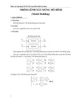
Fig. 21 In incremental programming, all dimensions are taken from the previous point. (Kelmar
Associates)
In incremental positioning, the work coordinates change because
each location is the zero point for the move to the next location,
Fig. 21.
On some parts, it may be desirable to change from absolute to
incremental, or vice versa, at certain points in the job. Inserting the
G90 (absolute) or the G91 (incremental) command into the pro-
gram at the point where the change is to be made can do this.
R Plane or Gage Height
The word-address letter R refers to a partial retraction point in the
Z axis to which the end of the cutter retracts above the work
surface to allow safe table movement in the X Y axes. It is often
called the rapid-traverse distance, gage height, retract or work
plane. The R distance is a specific height or distance above the
work surface and is generally .100 in. above the highest surface of
the workpiece, Fig. 22, which is also known as gage height. Some
manufacturers build a gage height distance of .100 in. into the
MCU (machine control unit) and whenever the feed motion in the
Z axis is called for, .100 in. will automatically be added to the
depth programmed.
When setting up cutting tools, the operator generally places a .100
in. thick gage on top of the highest surface of the workpiece. Each
tool is lowered until it just touches the gage surface and then its
28
length is recorded on the tool list. Once the gage height has been
set, it is not generally necessary to add the .100 in. to any future
depth dimensions since most MCUs do this automatically.
Fig. 22 Using a .100 in. gage block to set the gage height or R0 on the work surface. (Kelmar
Associates)
Cutter Diameter Compensation
Cutter diameter compensation (CDC) changes a milling cutter’s
programmed centerline path to compensate for small differences
in cutter diameter. On most MCUs, it is effective for most cuts
made using either linear or circular interpolation in the X-Y axis,
but does not affect the programmed Z-axis moves. Usually com-
pensation is in increments of .0001 in. up to +1.0000 in., and
usually most controls have as many CDCs available as there are
tool pockets in the tool storage matrix.
The advantage of the CDC feature is that it:
1. allows the use of cutters that have been sharpened to a
smaller diameter.
2. permits the use of a larger or smaller tool already in the
machine’s storage matrix.
3. allows backing the tool away when roughing cuts are required
due to excessive material present.
29
4. permits compensation for unexpected tool or part deflection, if
the deflection is constant throughout the programmed path.
The basic reference point of the machine tool is never at the
cutting edge of a milling cutter, but at some point on its periphery.
If a 1.000 in. diameter end mill is used to machine the edges of a
workpiece, the programmer would have to keep a .500 in. offset
from the work surface in order to cut the edges accurately, Fig. 23.
The .500 offset represents the distance from the centerline of the
cutter or machine spindle to the edge of the part. Whenever a part
is being machined, the programmer must calculate an offset path,
which is usually half the cutter diameter.
Fig. 23 Cutter-diameter compensation must be used when machining with various size
cutters. (Kelmar Associates)
Modern MCUs, which have part surface programming, automati-
cally calculate centerline offsets once the diameter of the cutter for
each operation is programmed. Many MCUs have operator-entry
capabilities which can compensate for differences in cutter diam-
eters; therefore an oversize cutter, or one that has been sharp-
ened, can be used as long as the compensation value for oversize
or undersize cutters is entered.
30
CNC Bench-Top Milling and Turning Centers
Bench-top teaching machines are well suited for teaching
purposes because neither the student or the teacher are intimated
by the size or complexity of the machines. They are easy to
program and perform machining operations similar to industrial
machines with smaller workpiece and lighter cuts. Bench-top
machines are relatively inexpensive and ideal for teaching basic
CNC programming.
Vertical machining centers and turning centers are the most
common CNC machines used in industry. For teaching purposes,
two types of CNC Bench-Top machines, the lathe and the mill, will
be used because they use the same basic programming features
and the Fanuc compatible controls as industrial machines. Most of
the G and M codes are the same for CNC Bench-top teaching
machines and industrial machines. Since programming codes do
vary slightly with manufacturers, it is always wise to
consult the programming manual for each specific machine to
avoid crashes or scrap work.
The 3-axes bench-top CNC vertical machining center (mill) with
the Fanuc compatible controller, Fig. 24, is ideal for teaching the
basics of CNC mill programming. It includes all important G and M
codes, milling cycles, subroutines, etc. and can be programmed in
inch or metric dimensions in both incremental and absolute pro-
gramming. Some models are equipped with a graphics display
that allows the operator to test-run the program on the computer
screen without cutting a part. This is a safe way to check the
accuracy of a program, to prevent crashes and scrap work,
without actually running the machine.
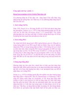
Fig. 24 Novamill
A compact 3 axis CNC bench milling
machine suitable for all levels of education
and technical training. The Novamill is
controlled via a standard keyboard or
Desk-Top Tutor connected to a PC. An
optional 6 station Automatic Tool Changer
(ATC) is also available. (Denford Inc.)
31
The CNC Bench-Top turning center (lathe), Fig. 25 is excellent
for teaching the basics of CNC lathe programming. It uses the
same standard G and M codes as the larger machines, can be
programmed in inch or metric dimensions in both absolute and
incremental programming. Many teaching machines also are
equipped with canned cycle processing and canned thread-cutting
cycles. Some models are equipped with a graphic display that
allows a student to simulate (test run) the cutting action of the
CNC program on the computer screen without actually cutting a
part on the machine. This allows the student to check the program
for accuracy and make corrections which avoids machine crashes,
damage, and scrap parts.
Fig. 25 Novaturn
A compact 2 axis CNC bench turning
center suitable for all levels of education
and technical training. The Novaturn is
controlled via a standard keyboard or
Desk-Top Tutor connected to a PC.
(Denford Inc.)
32
CNC Programming Hints - MILLING
Machine reference point (maximum travel of machine)
Machine X Y zero point (could be tool change point)
Part X Y zero point (programming start point)
Indicates the tool change position. A G92 code will
reset the axis register position coordinates to this
position.
For a program to run on a machine, it must contain the follow-
ing codes:
M03 To start the spindle/cutter revolving.
Sxxx The spindle speed code to set the r/min.
Fxx The feed rate code to move the cutting tool or
workpiece to the desired position.
ANGLES:
The X Y coordinates of the start point and end point of
the angular surface plus a feed rate (F) are required.
Z CODES:
• A Z dimension raises the cutter above the work surface.
• A Z- dimension feeds the cutter into the work surface.
• Z.100 is the recommended retract distance above the
work surface before a rapid move (G00) is made to
another location.
RADII / CONTOUR Requirements:
• The
start
point of the arc (XY coordinates)
• The
direction
of cutter travel (G02 or G03)
• The
end
point of the arc (XY coordinates)
• The
center
point of the arc (IJ coordinates) or the arc
radius)
33
Fig. 26 A sample flat part used for CNC
programming and machining (Kelmar
Associates)
34
Milling and Drilling Programming
Program Notes: (Fig. 26)
• Program in the absolute mode starting at the tool change
position at the top left corner of the print.
• The material is aluminum (300 CS), feedrate 10 in/min.
• The cutting tool is a .250 in. diameter high speed steel 2-flute
end mill.
• Mill the 1 in. square slot.
• Drill the two .250 in. diameter holes, .250 in. deep.
• Mill the .250 in. wide angular slot, .125 in. deep.
• Mill the .250 in. wide circular groove, .125 in. deep.
• After the job is completed, return to the tool change position.
Programming:
% (rewind stop code / parity check)
2000 (program number)
N5 G92 X-1.000 Y1.000 Z1.000
G92 programmed offset of reference point (tool change
position)
X-1.000 tool set at 1.000 to the left of the part.
Y1.000 tool set at 1.000 above the top edge of the part.
Z1.000 the end of the cutter is 1.000 above the top surface
of the part.
N10 G20 G90
G20 inch data input.
G90 absolute programming mode.
N15 M06 T01
M06 tool change command.
T01 tool no. 1 (.250 diameter, 2-flute end mill).
N20 S2000 M03
S2000 spindle speed set at 2000 r/min.
M03 spindle on clockwise.
35
N25 G00 X0 Y0 Z.100
G00 rapid traverse rate to X0 Y0 at the top left corner of
the part.
Z.100 tool rapids down to within .100 of the work surface.
Machining the square groove
N30 X.375 Y 375
tool rapids to position A.
N35 G01 Z 125 F10
G01 linear interpolation.
Z 125 tool feeds .125 below the work surface.
F10 feed rate set at 10 in./min.
N40 X1.625 Y 375
X1.625 top groove cut to the right hand end.
Y 375 measurement did not change because it was set in
block N30.
N45 Y-1.625
Y-1.625 right hand side of the groove cut.
N50 X.375
X.375 bottom groove cut to the left side.
N55 Y 375
Y 375 left-hand side of groove cut; this completes the
groove.
N60 G00 Z.100
G00 rapid traverse mode.
Z.100 tool rapids to .100 above work surface.
Hole Drilling
N65 G00 X.875 Y 750
tool rapids to the top left hole location.