Tài liệu COMPUTER NUMERICAL CONTROL PROGRAMMING BASICS A Primer for the SkillsUSA/VICA Championships Steve docx
Bạn đang xem bản rút gọn của tài liệu. Xem và tải ngay bản đầy đủ của tài liệu tại đây (1.19 MB, 51 trang )
C
OMPUTER
N
UMERICAL
C
ONTROL
P
ROGRAMMING
B
ASICS
A Primer for the
SkillsUSA/VICA
Championships
Steve Krar Arthur Gill
Distributed to educational administrators,
instructors, students, and apprentices
with the compliments of
INDUSTRIAL PRESS, INC.
publishers of
MACHINERY’S HANDBOOK
“The Bible of the Machine Trades”
CALL FOR AUTHORS
Industrial Press is expanding its list of professional and educational titles in
addition to starting a new program in electronic publishing. If you have any
suggestions or actual writing plans, we encourage you contact us.
We are seeking new authors especially in the following fields:
CNC and CAD/CAM
Design
Electrical/Electronics
Industrial Engineering
Machine Shop/Tools/Metalworking
Maintenance
Manufacturing
Technical Mathematics
Quality Control/Reliability
Welding
Industrial Press provides specialized and personal assistance in all stages of
book publishing from writing the text, to layout, design and marketing. We
give authors the individualized attention needed in producing quality publica-
tions, and actively promote books to national and international markets.
For more information about submitting a proposal, please contact us and we
will forward our suggested guidelines:
John Carleo
Editor
Industrial Press, Inc.
200 Madison Avenue
New York, NY 10016-4078
Toll Free: 888-528-7852 ext. 18
Tel: 212-889-6330 ext.18
Fax: 212-545-8327
www.industrialpress.com
Computer
Numerical
Control
Programming
Basics
Steve Krar Arthur Gill
This book is not intended for sale under any circumstances.
INDUSTRIAL PRESS INC.
200 Madison Avenue, New York, NY 10016
Photo Credits - Allen Bradley, Deckel Maho Inc., Denford Inc., Emco
Maier Corp., Icon Corp., Kelmar Associates, Superior Electric Co.
Development Resources provided by Paul Koontz, Denford Inc.
Page Layout / Design - Coree Kilo Price, Denford Inc.
Library of Congress Cataloging-in-Publication Data
Krar, Steve F.
COMPUTER Numerical Control Programming Basics / Steve
Krar, Arthur Gill.
p. cm.
ISBN 0-07-023333-0
1. Machine Tools - Numerical Control. I. Gill, Arthur, date.
II Title.
TJ1189, K74 1999 89-12571
CIP
Some of the artwork for this book was processed electronically.
Computer Numerical Control Programming Basics
Copyright © 1999 by Kelmar Associates. All rights reserved.
Printed in the United States of America. Except as permitted
under the United States Copyright Act, no part of this
publication can be reproduced or distributed in any form or
means, or stored in a database or retrieval system without the
written permission of the publisher.
Send all inquiries to:
Kelmar Associates
420 Fitch Street, Welland, ON L3C 4W8
Phone: (905) 732-4193 E-mail:
Industrial Press Edition ISBN 0-8311-3131-4
CONTENTS
SECTION PAGE
Foreword 1
Preface 7
Cartesian Coordinate System 7
Machines Using CNC 9
Programming Systems 11
Point-to-Point or Continuous Path 13
Point-to-Point Positioning 14
Continuous Path (Contouring) 15
Interpolation 15
Programming Format 17
Programming for Positioning 23
Work Settings and Offsets 26
CNC Bench-Top Milling and Turning Centers 30
CNC Programming Hints — Milling 32
Milling and Drilling Programming 34
CNC Programming Hints – Turning 38
Fanuc Compatible Programming 39
Turning Programming 40
1
CNC Foreword
As the National Technical Committee Chairman for the Precision
Machining Technology portion of the Skills USA-VICA champion-
ships I get to see students of varying levels of competence com-
pete each year. Each year my Industry committee works very hard
to design a competition that is challenging but fair. Since both
Secondary and Post-Secondary students compete at the Nation-
als, the level of difficulty is always a topic of discussion. Of major
concern are the low scores in the CNC programming sections of
this national competition. Only basic CNC programming skills are
required to complete these portions of the competition. However,
the scores indicate that too many competitors do not have these
basic skills. Because the committee feels a responsibility to help
educators provide this basic knowledge to students interested in
manufacturing technology, the committee suggested that this
booklet be furnished to all Skills USA-VICA State Directors and all
instructors with a machining curriculum in that state.
This book can be photocopied with the written permission from
Kelmar Associates so that as many students as possible can be
exposed to this basic information; It is not for resale. The informa-
tion should also be furnished to all local and state precision ma-
chining technical committees so they can incorporate CNC Pro-
gramming in their competitions. The information is also available
on the Skills USA-VICA Precision Machining Technology web site.
The 1999 National competition had two CNC programming sta-
tions as part of the overall Precision Machining Technology portion
of the Skills USA Championships. Each of these CNC Program-
ming sections was worth 100 points. CNC programming repre-
sents 28% of the National competition. Contestants sent to the
nationals without this basic skill have no chance of winning a
medal and would have difficulty receiving a passing grade.
CNC TURNING: The average score of the secondary contestants
was 32.4 with the highest score being 100 and the lowest being
six contestants with zeros. The post-secondary scores were
higher, but still not where they should be. The average was 52.9,
with the highest score being 99 and the lowest being two
contestants with zeros.
2
CNC MILLING: The Milling programming scores were even lower.
Secondary average was 25.8 with a high of 100 and five contes-
tants with zeros. Post-secondary average was 25.7 with a high of
58 and four contestants with zero.
These scores indicate a definite lack of fundamental CNC
programming skills!
All contestants were given a guide to the Fanuc software that
would be used. The Fanuc software guide, that is used in over
80% of the CNC applications throughout the world, included all the
codes needed for the competition. Contestants were given time to
familiarize themselves with and ask questions about the comput-
ers and the software they would be using. Technical committee
members were shocked to find several contestants that did not
even have the basic computer skills to open the software program.
It is our recommendation that any school with a Precision Machin-
ing curriculum should be utilizing manual machines to provide a
basic understanding of and to develop basic skills related to the
fundamental machining processes. The focus of this phase should
be work-holding techniques, how metal is removed, tooling termi-
nology, proper speeds, feed and depth of cut for different materials
and obtaining geometric and size tolerances. After this basic
introduction to machining processes (utilizing manual machines)
instruction should quickly transition to CNC programming utilizing
and applying all the fundamental machining skills learned in the
manual-machining phase.
We are not suggesting that every school with a metalworking
program invest in costly full-sized CNC machines; just the oppo-
site is true. Inexpensive text books, trade literature, video tapes,
machine simulators (this is how the small bench-top CNC teaching
machines should be looked upon), and computer software is
available today. We also feel that the NIMS (National Institute for
Metalworking Skills) Machining, level I and II skill standards
should be incorporated into every school’s machining program.
3
Our National Skills USA Precision Machining Competition is
based on these standards!
Visit the NIMS web site: www.nims-skills.org
It is our hope that this booklet will get into the hands of all those
instructors, advisors, State Directors and local and state technical
committees that have anything to do with the Skills USA-VICA
Precision Machining competition and eventually into every preci-
sion machining curriculum in the United States.
4
Why CNC (Computer Numerical Control)?
It has been a privilege to be part of the Precision Machining
Technology Competition for the past 9 years. I am proud to have
the opportunity of working with the fine young people from all parts
of the United States. They deserve the best that the educational
system and VICA can provide to prepare them for a future in this
rapidly changing technological world and make their contribution
to the country’s economy.
My enthusiasm for VICA and the young competitors is still very
strong, however there seems to be a serious lack of preparation
for students from metalworking/manufacturing related courses in
the basic knowledge of CNC. CNC, not a new technology having
been around since 1957, is one of the key factors in the manufac-
ture of most products in the world today. A knowledge of CNC, for
a technology student, should rank in importance along with the
ability of speaking proper English and reading technical prints
(blueprints).
As a former educator and now the Team Leader of the CNC VICA
competition, I feel so sorry for contestants in the Milling and
Turning who sit in front of a computer and do not know how to load
a program or the basics of CNC programming. These students are
naturally frustrated that an educational system has shortchanged
them by not realizing that metalworking technology has changed
dramatically over the past 40 years. That some schools prepare
students for the National VICA Precision Machining Competition
with 50-year-old technical knowledge is something very difficult to
understand.
The International (World) competition eliminated conventional
machine tools from the precision machining competition in 1996,
and it now consists of 100% CNC competition. To send our na-
tional winner to the world competition without a good background
in CNC programming and machining would be a reflection on, and
a disgrace to the US educational system.
The educational community and National VICA must work
together to correct this lack of CNC knowledge and training. The
5
VICA CNC Programming Guide covers the basic CNC principles
and gives detailed explanation of each step in the programming
and turning a part. The time and money spent to prepare and
distribute this Guide will be wasted unless the metalworking/
manufacturing teacher is committed to introducing CNC as part of
the curriculum.
The following suggestions can be used to introduce CNC theory
and technology to metalworking/manufacturing courses:
1. Teach the basics of CNC using the VICA CNC Programming
Guide that should be supplemented by a textbook, visuals, video-
tapes, etc. - COST approximately $200.00.
2. Use the VICA CNC Programming Guide and textbook along
with CAD/CAM software that allows a student to simulate the
machining of a programmed part on the computer screen. - COST
approximately $600.00.
3. Use the VICA CNC Programming Guide, textbook, CAD/CAM
software, plus a CNC Bench-Top teaching size machine. This is
by far the best method since students can actually produce a real
part that they can hold and take home to show their parents. -
COST approximately $6,000.00
For more information from a leader in CNC educational
courseware, software, and Bench-Top Teaching machines contact:
Denford Inc.
1-800-886-9750
www.denford.com
E-mail:
The old argument that there are still many shops using old
technology is a fallacy used consciously or unconsciously by those
resisting changes. Over 90% of the machine tools manufactured
in the world have some form of CNC control, therefore conven-
tional (manual) machines should be used to provide only the basic
knowledge of machines and machining processes.
6
We must all do our part; State Directors, District Directors, School
Administrators, and Classroom Teachers to correct a problem long
overdue in technical education.
Steve Krar
CNC Team Leader
Precision Machining Technology
7
The term
numerical control
is a widely accepted and commonly
used term in the machine tool industry. Numerical control (NC)
enables an operator to communicate with machine tools through a
series of numbers and symbols.
NC which quickly became Computer Numerical Control (CNC) has
brought tremendous changes to the metalworking industry. New
machine tools in CNC have enabled industry to consistently
produce parts to accuracies undreamed of only a few years ago.
The same part can be reproduced to the same degree of accuracy
any number of times if the CNC program has been properly pre-
pared and the computer properly programmed. The operating
commands which control the machine tool are executed automati-
cally with amazing speed, accuracy, efficiency, and repeatability.
The ever-increasing use of CNC in industry has created a need for
personnel who are knowledgeable about and capable of preparing
the programs which guide the machine tools to produce parts to
the required shape and accuracy. With this in mind, the authors
have prepared this textbook to take the mystery out of CNC - to
put it into a logical sequence and express it in simple language
that everyone can understand. The preparation of a program is
explained in a logical step-by-step procedure, with practical ex-
amples to guide the student.
Cartesian Coordinate System
Almost everything that can be produced on a conventional ma-
chine tool can be produced on a computer numerical control
machine tool, with its many advantages. The machine tool move-
ments used in producing a product are of two basic types:
point-
to-point
(straight-line movements) and
continuous path
(contouring
movements).
The Cartesian, or rectangular, coordinate system was devised by
the French mathematician and philosopher Rene’ Descartes. With
this system, any specific point can be described in mathematical
Preface
8
terms from any other point along three perpendicular axes. This
concept fits machine tools perfectly since their construction is
generally based on three axes of motion (X, Y, Z) plus an axis of
rotation. On a plain vertical milling machine, the X axis is the
horizontal movement (right or left) of the table, the Y axis is the
table cross movement (toward or away from the column), and the
Z axis is the vertical movement of the knee or the spindle. CNC
systems rely heavily on the use of rectangular coordinates be-
cause the programmer can locate every point on a job precisely.
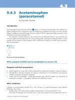
When points are located on a workpiece, two straight intersecting
lines, one vertical and one horizontal, are used. These lines must
be at right angles to each other, and the point where they cross is
called the
origin
, or
zero point
(Fig. 1)
Fig. 1 Intersecting lines form right angles and
establish the zero point (Allen-Bradley)
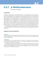
The three-dimensional coordinate planes are shown in Fig. 2. The
X and Y planes (axes) are horizontal and represent horizontal
machine table motions. The Z plane or axis represents the vertical
tool motion. The plus (+) and minus (-) signs indicate the direction
from the zero point (origin) along the axis of movement. The four
quadrants formed when the XY axes cross are numbered in a
counterclockwise direction (Fig. 3). All positions located in quad-
rant 1 would be positive (X+) and positive (Y+). In the second
quadrant, all positions would be negative X (X-) and positive (Y+).
In the third quadrant, all locations would be negative X (X-) and
negative (Y-). In the fourth quadrant, all locations would be posi-
tive X (X+) and negative Y (Y-).
Fig. 2 The three-dimensional
coordinate planes (axes) used in
CNC. (The Superior Electric
Company)
9
Fig. 3 The quadrants formed when the X and Y axes cross are used to accurately locate
points from the XY zero, or origin, point. (Allen-Bradley)
In Fig. 3 , point A would be 2 units to the right of the Y axis and 2
units above the X axis. Assume that each unit equals 1.000. The
location of point A would be X + 2.000 and Y + 2.000. For point B,
the location would be X + 1.000 and Y - 2.000. In CNC program-
ming it is not necessary to indicate plus (+) values since these are
assumed. However, the minus (-) values must be indicated. For
example, the locations of both A and B would be indicated as
follows:
A X2.000 Y2.000
B X1.000 Y-2.000
Machines Using CNC
Early machine tools were designed so that the operator was
standing in front of the machine while operating the controls. This
design is no longer necessary, since in CNC the operator no
longer controls the machine tool movements. On conventional
machine tools, only about 20 percent of the time was spent remov-
ing material. With the addition of electronic controls, actual time
spent removing metal has increased to 80 percent and even
higher. It has also reduced the amount of time required to bring
the cutting tool into each machining position.
10
Machine Types
Lathe
The engine lathe, one of the most productive machine tools, has
always been an efficient means of producing round parts (Fig.
4). Most lathes are programmed on two axes.
• The X axis controls the cross motion of the cutting tool.
Negative X (X-) moves the tool towards the spindle
centerline; positive X moves the tool away from the spindle
centerline.
• The Z axis controls the carriage travel toward or away from
the headstock.
Fig. 4 The main axes of a lathe or turning center. (Emco Maier Corp)
Milling Machine
The milling machine has always been one of the most versatile
machine tools used in industry (Fig. 5). Operations such as
milling, contouring, gear cutting, drilling, boring, and reaming are
only a few of the many operations which can be performed on a
milling machine. The milling machine can be programmed on
three axes:
• The X axis controls the table movement left or right.
• The Y axis controls the table movement toward or away from
the column.
• The Z axis controls the vertical (up or down) movement of
the knee or spindle.
11
Fig. 5 The main axes of a vertical machining center. (Denford Inc.)
Programming Systems
Two types of programming modes, the incremental system and
the absolute system, are used for CNC. Both systems have
applications in CNC programming, and no system is either right or
wrong all the time. Most controls on machine tools today are
capable of handling either incremental or absolute programming.
Incremental program
locations are always given as the distance
and direction from the immediately preceding point (Fig. 6). Com-
mand codes which tell the machine to move the table, spindle,
and knee are explained here using a vertical milling machine as
an example:
X axis
Y axis
Z axis
Positioning
Reference Point Systems
Incremental Absolute
12
Fig. 6 A workpiece dimensioned in the incremental system mode. (Icon Corporation)
• A “X plus” (X+) command will cause the cutting tool to be
located to the right of the last point.
• A “X minus” (X-) command will cause the cutting tool to be lo-
cated to the left of the last point.
• A “Y plus” (Y+) command will cause the cutting tool to be
located toward the column.
• A “Y minus” (Y-) will cause the cutting tool to be located away
from the column.
• A “Z plus” (Z+) command will cause the cutting tool or spindle
to move up or away from the workpiece.
• A “Z minus” (Z-) moves the cutting tool down or into the work-
piece.
In incremental programming, the G91 command indicates to the
computer and MCU (Machine Control Unit) that programming is in
the incremental mode.
Absolute program locations
are always given from a single fixed
zero or origin point (Fig. 7). The zero or origin point may be a
position on the machine table, such as the corner of the worktable
or at any specific point on the workpiece. In absolute dimensioning
and programming, each point or location on the workpiece is given
as a certain distance from the zero or reference point.
13
Fig. 7 A workpiece dimensioned in the absolute system mode. Note: All dimensions are given
from a known point of reference. (Icon Corporation)
• A “X plus” (X+) command will cause the cutting tool to be
located to the right of the zero or origin point.
• A “X minus” (X-) command will cause the cutting tool to be lo-
cated to the left of the zero or origin point.
• A “Y plus” (Y+) command will cause the cutting tool to be
located toward the column.
• A “Y minus” (Y-) command will cause the cutting tool to be lo-
cated away from the column.
In absolute programming, the G90 command indicates to the
computer and MCU that the programming is in the absolute mode.
Point-to-Point or Continuous Path
CNC programming falls into two distinct categories (Fig. 8). The
difference between the two categories was once very distinct.
Now, however, most control units are able to handle both point-to-
point and continuous path machining. A knowledge of both pro-
gramming methods is necessary to understand what applications
each has in CNC.
14
CNC Positioning
Systems
Point-to-Point
or
Positioning
Continuous Path
or
Contouring
Fig. 8 Types of CNC positioning systems (Kelmar Associates)
Point-to-Point Positioning
Point-to-point positioning is used when it is necessary to accu-
rately locate the spindle, or the workpiece mounted on the ma-
chine table, at one or more specific Iocations to perform such
operations as drilling, reaming, boring, tapping, and punching (Fig.
9). Point-to-point positioning is the process of positioning from one
coordinate (XY) position or location to another, performing the
machining operation, and continuing this pattern until all the
operations have been completed at all programmed locations.
Fig. 9 The path followed by point-to-point positioning to reach various programmed points
(machining locations) on the XY axis. (Kelmar Associates)
In Fig. 9 point 1 to point 2 is a straight line, and the machine
moves only along the X axis; but points 2 and 3 require that
motion along both the X and Y axes takes place. As the distance
in the X direction is greater than in the Y direction, Y will reach its
15
position first, leaving X to travel in a straight line for the remaining
distance. A similar motion takes place between points 3 and 4.
Continuous Path (Contouring)
Contouring
, or
continuous path machining
, involves work such as
that produced on a lathe or milling machine, where the cutting tool
is in contact with the workpiece as it travels from one programmed
point to the next. Continuous path positioning is the ability to
control motions on two or more machine axes simultaneously to
keep a constant cutter-workpiece relationship. The programmed
information in the CNC program must accurately position the
cutting tool from one point to the next and follow a predefined
accurate path at a programmed feed rate in order to produce the
form or contour required (Fig. 10)
Interpolation
The method by which contouring machine tools move from one
programmed point to the next is called
interpolation
. This ability to
Fig. 10 Types of contour
machining (A) Simple
contour; (B) complex
contour (Allen Bradley)
16
merge individual axis points into a predefined tool path is built into
most of today’s MCUs. There are five methods of interpolation:
linear, circular, helical, parabolic, and cubic. All contouring controls
provide linear interpolation, and most controls are capable of both
linear and circular interpolation. Helical, parabolic, and cubic
interpolation are used by industries that manufacture parts which
have complex shapes, such as aerospace parts and dies for car
bodies.
Linear Interpolation
Linear Interpolation
consists of any programmed points linked
together by straight lines, whether the points are close together or
far apart (Fig. 11). Curves can be produced with linear interpola-
tion by breaking them into short, straight-line segments. This
method has limitations, because a very large number of points
would have to be programmed to describe the curve in order to
produce a contour shape.
A contour programmed in linear interpolation requires the coordi-
nate positions (XY positions in two-axis work) for the start and
finish of each line segment. Therefore, the end point of one line or
segment becomes the start point for the next segment, and so on,
throughout the entire program.
Fig. 11 An example of two-axis linear interpolation. (Kelmar Associates)
17
Fig. 12 For two-dimensional circular interpolation the MCU must be supplied with the XY axis,
radius, start point, end point, and direction of cut. (Kelmar Associates)
Programming Format
Word address is the most common programming format used for
CNC programming systems. This format contains a large number
of different codes (preparatory and miscellaneous) that transfers
program information from the part print to machine servos, relays,
micro-switches, etc., to manufacture a part. These codes, which
conform to EIA (Electronic Industries Association) standards, are
in a logical sequence called a
block of information
. Each block
should contain enough information to perform one machining
operation.
Word Address Format
Every program for any part to be machined, must be put in a
Circular Interpolation
The development of MCUs capable of
circular interpolation
has
greatly simplified the process of programming arcs and circles. To
program an arc (Fig. 12), the MCU requires only the coordinate
positions (the XY axes) of the circle center, the radius of the circle,
the start point and end point of the arc being cut, and the direction
in which the arc is to be cut (clockwise or counterclockwise) See
Fig. 12. The information required may vary with different MCUs.
18
format that the machine control unit can understand. The format
used on any CNC machine is built in by the machine tool builder
and is based on the type of control unit on the machine. A vari-
able-block format which uses words (letters) is most commonly
used. Each instruction word consists of an address character,
such as X, Y, Z, G, M, or S. Numerical data follows this address
character to identify a specific function such as the distance, feed
rate, or speed value.
The address code G90 in a program, tells the control that all
measurements are in the absolute mode. The code G91, tells the
control that measurements are in the incremental mode.
Codes
The most common codes used when programming CNC ma-
chines tools are
G-codes
(preparatory functions), and
M codes
(miscellaneous functions). Other codes such as F, S, D, and T are
used for machine functions such as feed, speed, cutter diameter
offset, tool number, etc.
G-codes are sometimes called cycle codes because they refer to
some action occurring on the X, Y, and/or Z axis of a machine tool,
Fig. 13.
The G-codes are grouped into categories such as Group 01,
containing codes G00, G01, G02, G03. which cause some move-
ment of the machine table or head. Group 03 includes either
absolute or incremental programming, while Group 09 deals with
canned cycles.
A G00 code rapidly positions the cutting tool while it is above the
workpiece from one point to another point on a job. During the
rapid traverse movement, either the X or Y axis can be moved
individually or both axes can be moved at the same time. Although
the rate of rapid travel varies from machine to machine, it ranges
between 200 and 800 in./min (5 and 20 m/min).
19
Fig. 13 The functions of a few common G-codes. (Deckel Maho, Inc.)
The G01, G02, and G03 codes move the axes at a controlled
feedrate.
• G01 is used for straight-line movement (linear interpolation).
• G02 (clockwise) and G03 (counterclockwise) are used for arcs
and circles (circular interpolation).
G00
RAPID TRAVERSE
G01
LINEAR INTERPOLATION
(STRAIGHT LINE MOVEMENT)
G02
CIRCULAR INTERPOLATION
(CLOCKWISE)
G03
CIRCULAR INTERPOLATION
(COUNTERCLOCKWISE)
20
Group Code Function
01 G00 Rapid positioning
01 G01 Linear interpolation
01 G02 Circular interpolation clockwise (CW)
01 G03 Circular interpolation counterclockwise (CCW)
06 G20* Inch input (in.)
06 G21* Metric input (mm)
G24 Radius programming (**)
00 G28 Return to reference point
00 G29 Return from reference point
G32 Thread cutting (**)
07 G40 Cutter compensation cancel
07 G41 Cutter compensation left
07 G42 Cutter compensation right
08 G43 Tool length compensation positive (+) direction
08 G44 Tool length compensation minus (-) direction
08 G49 Tool length compensation cancel
G84 Canned turning cycle (**)
03 G90 Absolute programming
03 G91 Incremental programming
(*) - on some machines and controls, these may be G70 (inch) and
G71 (metric)
(**) - refers only to CNC lathes and turning centers.
Fig. 14 Some of the most common G-codes used in CNC programming.
M or miscellaneous codes are used to either turn ON or OFF
different functions which control certain machine tool operations,
Fig. 15.
M-codes are not grouped into categories, although several codes
may control the same type of operations such as M03, M04, and
M05 which control the machine tool spindle.
• M03 turns the spindle on clockwise
• M04 turns the spindle on counterclockwise
• M05 turns the spindle off