Cranes – Design, Practice, and Maintenance phần 4 potx
Bạn đang xem bản rút gọn của tài liệu. Xem và tải ngay bản đầy đủ của tài liệu tại đây (1014.27 KB, 35 trang )
Drives; Calculating Motor Powers 85
3.6 Calculating the needed power of the crane-
travelling motors. Wheelslip control – how to
calculate the forces through skewing of the
crane and trolley
Factors to be considered are:
1. The resistance due to nominal travelling.
2. The resistance due to the influence of the wind.
3. The resistance due to the acceleration of the rotating masses.
4. The resistance due to the acceleration of the linear moving
masses.
Main characteristics
Example
Loaded Crane
Weight of crane mt W
1
G1300 t
Weight of load mt W
2
G40 t
Total weight mt W
t
G1340 t
Crane travelling speed m͞min 45 m͞min
m͞sec ûG0,75 m͞sec
Total efficiency of the gearings
η
t
η
t
G0,9
Wheel resistance of the crane
travelling wheels kN͞t fG5kg͞tG0,05 kN͞t
Influence of the (side) wind:
F
w
GΣ(A · C ·
η
2
) · q kN
qG150 N͞m
2
Aû
w
G15,5 m͞sec
qG200 N͞m
2
Aû
w
G17,9 m͞sec
qG275 N͞m
2
Aû
w
G21 m͞sec F
w
G510 kN
qG400 N͞m
2
Aû
w
G25,3 m͞sec
Acceleration time:
t
a
G sec sec t
a
G6 sec
Cranes – Design, Practice, and Maintenance86
Example
Loaded Crane
Acceleration
aG m͞sec
2
m͞sec
2
aG
û
t
G
0,75
6
G0,125 m͞sec
2
Motor speed: n
m
rev͞min n
m
G1800 rev͞min
Wheel diameter: D
w
m D
w
G0,9 m
Reduction between motor and
wheel:
iG
n
m
·
π
· D
w
û
iG
1800 ·
π
· 0,9
45
G113
J
t
GΣ
mom
of inertia of the rot. parts kg m
2
J
motors
B
J
brake sheaves͞couplings
B
J
gearbox, reduced
B
J
total
GJ
t
J
t
G2kgm
2
Calculation kN kW
1. Resistance due to
nominal travelling:
F
1
GW
t
· f kN F
1
G1340 · 0,05
G67 kN
N
1
G
F
1
· û
η
t
kW N
1
G
67 · 0,75
0,9
G55,8 kW
2. Resistance due to
wind:
F
2
GF
w
kN F
2
G510 kN
N
2
G
F
2
· û
η
t
kW N
2
G
510 · 0,75
0,9
G425 kW
Drives; Calculating Motor Powers 87
Calculation kN kW
3. Resistance due to
the acceleration of
the rotating masses:
ω
G
n
m
· 2 ·
π
60
rad͞sec
ω
G
1800 · 2 ·
π
60
G188,4 rad͞sec
M
a
G
J
t
·
ω
t
a
Nm M
a
G
2 · 188,4
6
G62,8 Nm
F
3
kN —
(remains internal
in the drive)
N
3
G
M
a
· n
m
9550
kW N
3
G
62,8 · 1800
9550
G11,8 kW
4. Resistance due to
the acceleration of
the linear moving
masses:
F
4
G
W
t
· û
t
a
kN F
4
G
1340 · 0,75
6
G167,5 kN
N
4
G
F
4
· û
η
t
kW N
4
G
167,5 · 0,75
0,9
G139,5 kW
Lateral forces on the
Addition travelling wheels Motor power
1. Nominal travelling F
1
G67 kN N
1
G55,8 kW
2. Wind qG275 N͞m
2
F
2
G510 kN N
2
G425 kW
Total, for nominal
travellingCwind ΣFG577 kN ΣNG480,8 kW
Cranes – Design, Practice, and Maintenance88
Lateral forces on the
Addition travelling wheels Motor power
During acceleration:
1. Nominal travelling F
1
G67 kN N
1
G55,8 kW
2. Wind, qG275 N͞m
2
F
2
G510 kN N
2
G425 kW
3. Acceler. rot. masses,
t
a
G6 sec F
3
G−kN N
3
G11,8 kW
4. Acceler. lin. masses,
t
a
G6 sec F
4
G167,5 kN N
4
G139,5 kW
Total during acceleration ΣF
a
G744,5 kN ΣN
4
G632,1 kW
Overload factor of motors
during acceleration
f
a
GM
max
: M
nom
f
a
G160 percent ΣNG
632,1
1,6
G395 kW
Take motors, each 20 kW; so 24 motors.
Total available power NG24 · 20G480 kW.
The influence of a slope
If a crane has to drive up a slope, an additional resistance has to be
overcome. Assume that a rubber tyred gantry (RTG) has to run against
the slope of
α
G1 degree. The total weight of the loaded RTG is Q
t
G
165 tons; the crane travelling speed is
ûG135 m͞minG2,25 m͞sec
F
slope
GQ
t
· 10
3
· g · sin
α
(N)
F
slope
G165 · 10
3
· 9,81 · 0,0174G28 164 NG28,164 kN
N
slope
G
F
slope
· û
η
G
28,164 · 2,25
0,9
G70,4 kW
Wheelslip control
– Check the minimum wheel load on a driven crane wheel: P
1
G
kN
– Check the maximum driving force that the crane travelling motor
can exert on the circumference of the driven wheel (traction force):
P
2
G
f
a
· N ·
η
û
kN
Drives; Calculating Motor Powers 89
– Friction coefficient between rail and wheel: muGP
2
͞P
1
– Allowed is muG0,12.
Skewing of the crane and trolley
Cranes, and trolleys, can skew. This can cause severe wear and tear of
the rails and the travelling wheels. The FEM standards mention the
following (in booklet 2) about skew:
2.2.3.3 Transverse reactions due to rolling action
When two wheels (or two bogies) roll along a rail, the couple formed by the
horizontal forces normal to the rail shall be taken into consideration. The
components of this couple are obtained by multiplying the vertical load
exerted on the wheels (or bogies) by a coefficient
λ
which depends upon
the ratio of the span
ρ
to the wheelbase a.
(1)
(1)
By ‘wheelbase’ is understood the centre distance between the outermost pairs of wheels, or,
in the case of bogies, the centre distance between the fulcrum pins on the crane structure
of the two bogies or bogie systems. Where horizontal guiding wheels are provided, the
wheelbase shall be the distance between the rail contact points of two horizontal wheels.
As shown in the graph [Fig. 3.6.2], this coefficient lies between 0,05 and 0,2
for ratios of
ρ
͞a between 2 and 8.
However DIN and other standards give a more complex calculation
about the horizontal forces through skewing. This calculation leads to
greater forces than those mentioned in Fig. 3.6.2.
Advice
– Take the skew forces on crane- and trolley wheels as a minimum
as 10 percent of the maximum wheel load.
– Take the skew forces on crane- and trolley wheels as 20 percent of
the maximum wheel load for cranes and trolleys running ûG
150 m͞m or more.
– Also check the calculations according to Fig. 3.6.2.
In order to keep the skewing forces on a crane travelling mechanism
under reasonable control, the length͞width ratio, being the relation
between the railspan or railgauge, and the centre distance between the
fulcrum pins of the crane travelling mechanism under each corner
ρ
:a
or L:B, should be at least 6 :1.
Cranes – Design, Practice, and Maintenance90
Fig. 3.6.1
Fig. 3.6.2
Drives; Calculating Motor Powers 91
3.7 The rating of the motors
Up to now, we have mentioned the following for the motors:
– the power in kW;
– the torque in Nm;
– the number of revolutions per minute;
– the starting torque, f
a
, being the torque which the motor and the
drive can develop during a certain number of seconds, when
accelerating the crane or trolley.
For a crane or trolley motor the normal torque–speed diagram of a
DC-Full Thyristor motor or an AC-Frequency controlled motor is:
Fig. 3.7.1 Torque–speed diagram
MG
N · 9550
n
Nm
where
MGmotor torque in Nm;
NGthe number of kW;
nGthe number of revolutions per minute of the motor.
The motor of a crane or trolley runs intermittently.
If we consider the trolley travel motor of a bulk unloader, the cycle
diagram in Fig. 3.7.2 is produced.
Cranes – Design, Practice, and Maintenance92
Fig. 3.7.2 Cycle diagram
Cycle
Only for the trolley travel motor
1. Grab digs in and closes t
1
sec M
1
G0
2. Grab is hoisted to above
the coaming t
2
sec M
2
G0
3. Grab is hoisted.
Accelerating the trolley with
full grab t
3
sec M
3
Gf
a
· M
4. Grab is hoisted to max. level
and hoist movement stops.
Travelling of the trolley with
full grab at nom. speed t
4
sec M
4
GM
5. Grab is opened above the
hopper.
Decelerating the trolley with
full grap to zero speed t
5
sec M
5
Gf
a
· M
6. Grab is further opened.
Trolley does not move t
6
sec M
6
G0
7. Grab remains open.
Trolley, with empty grab,
accelerates toward the vessel t
7
sec M
7
Gf
a
· M
Drives; Calculating Motor Powers 93
8. Travelling of the trolley at
nominal speed. At certain
moment the grab is lowered t
8
sec M
8
G
∼
0,8 · M
9. Decelerating the trolley with
empty grab to zero speed.
Grab is further lowered into
the vessel t
9
sec M
9
Gf
a
· M
10. Trolley is at rest. Grab is
lowered into the hatch and
into the material t
10
sec M
10
G0
We can deduce from this scheme the rating R:
RG
t
1
BCt
2
BCt
3
Ct
4
Ct
5
Ct
6
BCt
7
Ct
8
Ct
9
Ct
10
B
Σ(t
1
ët
10
)
for t
1
; t
2
; t
6
and t
10
MG0.
The normal motor ratings are:
Container
Container stacking
quay cranes cranes Grab-unloaders
%%%
Hoisting 60 60* 89–90
Trolley travelling 60 40–60 80–90
Trolley slewing 40 40 –
Boom hoisting 25–40 – 25–40
Crane travelling 40 60 60
Level luffing Level luffing general
grabbing crane cargo crane
%%
Hoisting 60 40–60
Luffing 60 40–60
Slewing 60 40–60
Crane travelling 25–40 25–40
Cranes – Design, Practice, and Maintenance94
3.8 The root-mean-square calculation
FEM, booklet 5 of 1998 mentions:
5.8.1.3 THERMAL CALCULATION OF THE MOTOR
5.8.1.3.1 Mean equivalent torque
In order to carry out the thermal calculation, the mean equivalent torque
must be determined as a function of the required torque during the working
cycles, by the formula:
M
med
G
1
M
2
1
· t
1
CM
2
2
· t
2
CM
2
3
· t
3
C···CM
2
8
· t
8
CM
2
9
· t
9
CM
2
10
· t
10
Σt
1
ët
10
t
1
,t
2
,t
3
, t
n
are the periods during which the different torque values are
produced; periods of rest are not taken into account.
M
1
,M
2
,M
3
, M
n
are the calculated torque values, in taking into account
all the inertia forces including the one of the rotor mass of the motor.
In the case of variable loads, at least a maximum of 10 successive working
cycles for the predimensioning, must be taken into account (see definition
2.1.2.2.).
However this RMS system should never be used to try to reduce the
motor power to a level lower than that calculated by the earlier
methods. (This RMS calculation is more or less obsolete and should
only be used for DC systems.)
3.9 The current supply of a crane by a diesel
generator set: calculation methods and
warnings
Many cranes have a diesel generator set, mounted on the crane itself.
In this case, the current supply by a high or medium voltage net is
avoided and the crane is made totally independent.
The diesel generator set itself does not provide difficult problems,
however some issues have to be addressed before the most suitable gen-
erator set can be installed. The diesel builders commonly use the follow-
ing notations:
– Stand-by power rating: This is the ‘top’ power which the diesel can
deliver. It can be delivered over a short period of several hours for
a restricted number of times per year.
– Continuous rating: This is the power which the diesel can deliver
continuously for instance for driving a ship. The ‘continuous
rating’ is approximately 70–80 percent of the ‘stand-by rating’.
Drives; Calculating Motor Powers 95
– Prime power rating: This must be defined as ‘the net prime power
at the flywheel; no fan losses’. It is then the mechanical power that
the diesel is delivering on its flywheel. The diesel can for instance
deliver this power to a generator which is driving a crane. This
generator has to deliver power to the motors of the mechanisms in
the crane. The kW loads which the different mechanisms need vary
during each cycle of the crane. The ‘Prime rating’ of the diesel
should cover these needs.
– Load in one step: This is the load which the diesel can take if a
sudden load is asked from the generator set. It is approximately 60
percent of the stand-by rating; it then gives a dip of the frequency
of the generator of approximately 10 percent. If the diesel is turbo-
loaded, it takes approximately 2 seconds for the turbos to give the
electronic controlled diesel the necessary extra power to recover,
unless a dummy load of resistances gives a particular bottom load
to the diesel, which forces the turbo to run continuously.
Summarizing (example):
1. Stand-by power rating
(‘x’ hours, ‘y’ times per year) 900 kW
2. Continous rating 0,7 · 900G630 kW up to
(e.g. driving a ship) 0,8 · 900G720 kW
3. Prime power rating
(‘net prime power at the flywheel;
no fan losses’) 0,9 · 900G810 kW
4. Load in one step rating 0,6 · 900G540 kW
These figures are given for example only; they are dependent on
the characteristics which the diesel manufacturers provide. Let us
assume that a container quay crane has to be driven by a diesel
generator set which is mounted on the crane itself.
To be driven are:
– the hoisting mechanism;
– the trolley travelling mechanism;
– the crane travelling mechanism;
– (incidentally) the boom-hoist mechanism;
– all auxiliary mechanisms, such as lighting, heating, air con-
ditioning and elevator or lift.
Note: The carbon deposit in the cylinders and the turbocharger as well
as the lube-oil slurry pollute the diesel and decrease its output.
The scheme is shown in Fig. 3.9.1.
Cranes – Design, Practice, and Maintenance96
Fig. 3.9.1 Scheme of a diesel generator set
(a) The Direct Current Full Thyristor system
With a Direct Current Full Thyristor system (DC-FT) the normal
torque–speed diagram for the electrical motor of the mechanism is as
follows.
The current that the generator behind the diesel has to deliver is
proportional to the required power that the electrical motor of the
mechanism has to give (the cos-phi during acceleration varies between
0 and 0,75).
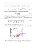
The DC-FT motor asks approximately 160 percent current when the
motorspeed nG0 and MG160 percent.
Fig. 3.9.2 DC FT torque–speed diagram
Drives; Calculating Motor Powers 97
The necessary power in kW is the product of n · M; in this case, 1,6
is the factor indicating the maximum torque during acceleration.
The possibilities of simultaneous working mechanisms are as Table
3.9.2. A diesel with an output of approximately 1450 kW Prime Power
Rating will do the job for this DC-FT installation, when the f
a
factor
is in accordance with the figures mentioned in Table 3.9.2. Bear in mind
the extra loss of power of a diesel in high temperatures or difficult
climatic conditions.
Feeding back into a diesel should be considered. Fortunately, the
number of motor kWs to be absorbed by the diesel, can then be multi-
plied with the efficiencies. The diesel itself can take 10 to 14 percent of
the rated output as regenerative loading, depending on the internal fric-
tion of the engine.
Table 3.9.1
DC-FT A B C D E
Auxiliaries
(lighting,
heating,
Trolley Boom Crane air conditioning,
Hoisting travelling hoist travel maintenance
mechanism mechanism mechanism mechanism crane; pumps)
Number of 600 kW 200 kW 250 kW 400 kW 80 kW
kiloWatts f
a
G1,6 f
a
G2 f
a
G2 f
a
G2
Efficiency of
the motor(s) etc. 0,9 0,85 0,85 0,85 0,9
Efficiency
between motor(s)
and generator 0,95 0,95 0,95 0,9 1
Efficiency of
the generator 0,95 0,95 0,95 0,95 0,95
Efficiency between
generator and diesel 1 (or 0,9 if there is a gearbox between generator and diesel)
η
1
η
2
η
2
η
3
η
4
The total efficiency is:
η
1
G0,9 · 0,95 · 0,95 · 1G0,812
η
2
G0,85 · 0,95 · 0,95 · 1G0,767
η
3
G0,85 · 0,9 · 0,95 · 1G0,726
η
4
G0,9 · 1 · 0,95 · 1G0,855
Cranes – Design, Practice, and Maintenance98
Table 3.9.2
Necessary diesel output
DC-FT kW (kW)
I A. Hoisting͞accelerating 600 · 1,6G 960 960 :0,812G1182
B. Auxiliaries G 80 80 :0,855G 93,5
TotalG1040 Diesel outputG1275,5
II A. Hoisting G 600 600 :0,812G 739
B. Trolley travelling͞accelerating 200 · 2G 400 400 :0,767G 521.5
E. Auxiliaries G 80 80 :0,855G 93,5
TotalG1080 Diesel outputG1354
III B. Trolley travelling G 200 200 :0,767G 261
D. Crane travelling͞accelerating 400 · 2G 800 800 :0,726G1102
E. Auxiliaries G 80 80 :0,855G 93,5
TotalG1080 Diesel outputG1456,5
IV D. Crane travelling (against storm) 400 · 2G 800 800 :0,726G1102
E. Auxiliaries G 80 80 :0,855G 93,5
TotalG 880 Diesel outputG1195,5
In our case we consider the following for feeding back to the diesel:
Table 3.9.3
Feed back:(Peak)
DC-FT kW (kW)
a. Lowering – decelerating 600 · 1,6G960 960 · 0,812G779
b. Trolley travelling – deceleration 200 · 2 G400 400 · 0,767G307
1086
(The mechanical efficiency of the mechanism is reversed)
This results in feedback of 1086 kW.
The diesel can dissipate 10 percent of 1450 kWG145 kW
To be dissipated by the flywheel or resistancesG941 kW
The energy, to be dissipated by the flywheel or resistances, will also
apply if the crane is being driven by the maximum windforce, including
the auxiliaries. This figure should always be checked.
The number of kiloWatts required of the diesel could be restricted
somewhat by using a mechanism with a ‘constant power’ characteristic.
In this case the factor f
a
could be reduced, giving a somewhat smaller
diesel output reduction. However in that case, the average acceleration
and deceleration of the movement is also reduced, which influences the
Drives; Calculating Motor Powers 99
acceleration and deceleration time of the mechanism. Through this the
throughput of the crane becomes less. Thus, if throughput is an impor-
tant feature, no reduction should be made in the average acceleration
and deceleration, otherwise the cycle time will lengthen, and throughput
will be reduced.
Moreover, care must be taken as the PLC used in the crane can be
influenced by quite a small dip in the diesel engine power output and
even stop the crane.
(Use an UPS – uninterruptible power supply to prevent a dip of
the PLC)
By fine tuning the diesel generator set, the time necessary for building
up the diesel power (power response) to meet sudden demand, can be
reduced somewhat. The main point is that the diesel generator set must
be able to follow the fast and sudden changing load demands of the
crane.
(b) The Alternating Current Frequency Control system
With the most modern alternating-current frequency control system
(AC-Fr.C) the normal torque–speed diagram for the electric motor can
be made as in Fig. 3.9.3. The current that the generator behind the
Fig. 3.9.3 AC frequency control: torque–speed diagram for hoisting/lowering
Cranes – Design, Practice, and Maintenance100
diesel has to deliver is proportional to the power (in kW) that the elec-
tric motor of the mechanism has to give.
– The cos-phi is approximately 0,95.
– AC-Fr.C asks approximately 0 percent current when nG0 and
MG160 percent.
– The peak torque of the motor follows the curve M · n
2
GC.
– The necessary power P in kW is the product of n · M; just as it is
in the Ward–Leonard–Kra
¨
mer system.
Take:
N
a
G1,25 · power of the hoisting mechanism.
(The factor of 1,25 is used to produce some reserve power for accelera-
tion, etc. The acceleration time then will be somewhat larger than with
the diesel driven FT systems of Table 3.9.2.)
Total efficiency:
η
1
G0,9 · 0,95 · 0,95 · 1G0,812
η
2
G0,9 · 1 · 0,95 · 1 G0,855
The possibilities of simultaneously working mechanisms are shown in
Table 3.9.5.
Table 3.9.4
AC-Fr.CABCDE
Auxiliaries
(lighting,
heating,
Trolley Boom Crane air conditioning,
Hoisting travelling hoist travel maintenance
mechanism mechanism mechanism mechanism crane, pumps)
Number of 600 kW 200 kW 250 kW 400 kW 80 kW
kilowatts f
a
G1,25 f
a
G2 f
a
G1,25 f
a
G2
Efficiency of
the motor(s) etc. 0,9 0,9 0,9 0,9 0,9
Efficiency
between motor(s)
and generator 0,95 0,95 0,95 0,95 1
Efficiency of
the generator 0,95 0,95 0,95 0,95 0,95
Efficiency between
generator and diesel 1 (or 0,9 if there is a gearbox between generator and diesel)
η
1
η
1
η
1
η
1
η
2
Drives; Calculating Motor Powers 101
Table 3.9.5
Necessary diesel output
AC-Fr.C kW (kW)
I A. Hoisting͞accelerating 600 (600 · 1,25) :0,812G 923,6
B Auxiliaries 80 80 :0,855G 93,5
Total 680 Diesel outputG1017
II A. Hoisting 600 (600 · 1) :0,812G 739
B. Trolley travelling͞accelerating 200 (200 · 2) :0,812G 492,5
E. Auxiliaries 80 80 :0,855G 93,5
Total 880 Diesel outputG1325
III B. Trolley travelling 200 (200 · 1) :0,812G 246
D. Crane travelling͞accelerating 400 (400 · 2) :0,812G 985
E. Auxiliaries 80 80 :0,855G 93,5
Total 680 Diesel outputG1325
IV D. Crane travelling 400 (400 · 2) :0,812G985,5
(against storm)
E. Auxiliaries 80 80 :0,855G 93,5
Total 480 Diesel outputG1079
A diesel with an output of approximately 1325 kW Prime Power Rating
can cope with this work. However, the acceleration time of the hoisting
mechanism is somewhat increased. Care must be taken over the extra
power losses of the diesel in high temperatures, the ability to follow the
fast and sudden changing load demands of the crane and the feed back
problems.
The crane builder should send the diesel generator manufacturer:
– a good calculation of the necessary Prime Power Rating;
– a cycle diagram of the crane, as well as the allowed voltage dip and
frequency dip.
3.10 Calculating the power needed for the slewing
motors of level luffing cranes
Factors to be considered are:
1. The resistance due to nominal slewing.
2. The resistance due to the influence of the wind.
3. The resistance due to the acceleration of the linear moving
masses.
4. The resistance due to the acceleration of the rotating masses.
Cranes – Design, Practice, and Maintenance102
Fig. 3.9.4 Caterpillar diesel generator set with large flywheel
Main Characteristics
Slewing mechanism.
Maximum radius m r
1
G40 m
Weight of the load tons W
1
G50 t
Weight of the slewing part of the
crane tons W
t
G400 t
Rev͞min of the slewing motor rev͞min nG1500 rev͞min
Speed of the crane rev͞min nG1,2 rev͞min
Total efficiency of the slewing
mechanism
ηη
G0,9
Type of crane Double boom crane
Scheme of the slewing part:
(For simplification, the points where the centre of gravity of the weights
and the points where the resultants of the wind load catch the crane,
have been taken on the same radius.)
W
1
, W
2
, GWeight of the different parts in tons.
r
1
, r
2
, GDistance of the centre of gravity of the crane parts and
the centre of the wind loads in m.
F
1
, F
2
, Gc · q · F
1
; c · q ·
η
· F
2
; c · q ·
η
· F
3
; is the wind load on
the different parts in kg; kN or t.
(See Section 1.5 for the calculation of c, q,
η
and F.)
Drives; Calculating Motor Powers 103
Fig. 3.10.1 Slewing luffing crane
1. The resistance due to nominal slewing
M
1
G(ΣW · R) ·
µ
· 10 kN m
where
M
1
Gresistance in kN m
ΣWGtotal weight in tons
R
1
Gthe resulting distance of the centre of gravity to the slewing
axle in m
µ
Gthe resistance of the slew bearingG0,006
W
1
G50 t r
1
G40 m W
1
· r
1
G2000 tm
W
2
G10 t r
2
G30 m W
2
· r
2
G300 tm
W
3
G40 t r
3
G20 m W
3
· r
3
G800 tm
W
4
G16 t r
4
G16 m W
4
· r
4
G256 tm
W
5
G60 t r
5
G0m W
5
· r
5
G0
W
6
G204 t r
6
G−2m W
6
· r
6
G−408 tm
W
7
G
70 t r
7
G−6m W
7
· r
7
G
−420 tm
Cranes – Design, Practice, and Maintenance104
ΣWG450 t ΣW · rG+2528 tm
R
1
G
ΣW · r
ΣW
m R
1
G
2528
450
GCentre of gravity of the G5,61 m
whole upper crane
M
1
G2528 · 0,006 · 10
G151,6 kN m
M
1 motor
G
M
1
i ·
η
iGn
motor
͞n
crane
iG
1500
1,2
G1250
M
1 motor
G
151,6 · 10
3
1250 · 0,9
N
1
G
M
1
· n
9550
G134,7 Nm
G
134,7 · 1500
9550
G21,15 kW
2. The resistance due to the influence of the wind
M
2
G(ΣF · r) · 10 kN m
FGc · q ·
η
· F (kg)
W (t) r (m) (here: qG15 kg͞m
2
) F · r (tm)
W
1
G50 t r
1
G40 m F
1
Gc · q ·
η
· F
1
G 250 F
1
· r
1
G10
W
2
G10 t r
2
G30 m F
2
Gc · q ·
η
· F
2
G 533 F
2
· r
2
G16
W
3
G40 t r
3
G20 m F
3
Gc · q ·
η
· F
3
G1500 F
3
· r
3
G30
W
4
G16 t r
4
G16 m F
4
Gc · q ·
η
· F
4
G 700 F
4
· r
4
G11,2
W
5
G60 t r
5
G0m F
5
Gc · q ·
η
· F
5
G3000 F
5
· r
5
G0
W
6
G204 t r
6
G−2m F
6
Gc · q ·
η
· F
6
G1600 F
6
· r
6
G−3,2
W
7
G70 t r
7
G−6m F
7
Gc·q·
η
· F
7
G
150 F
7
· r
7
G
−0,9
ΣFG7800 kg ΣF · rG63,1 tm
Drives; Calculating Motor Powers 105
M
2
G63,1 · 10G631 kN m
M
2 motor
G
M
2
· 10
3
i ·
η
Nm
M
2 motor
G
631 · 10
3
1250 · 0,9
G561 Nm
N
2
G
M
2 motor
· n
9550
kW N
2
G
561 · 1500
9550
G88 kW
3. The resistance due to the
acceleration of the linear
moving masses.
M
3
G
θ
ΣT · 10 kN m
TGthe inertia movement of a
certain part, regarded to
be the centre of rotation
of the upper crane.
Simplified:
‘Point’–(load) TGm
1
· r
2
1
‘Line’–(r from centre TG
1
12
· m
2
· L
2
2
of gravity)
Cm
2
r
2
2
T in
ton metre͞sec
2
θ
Gacceleration
(For heavy duty cranes
t
a
G6–8 sec) in radii͞sec
2
See Fig. 3.10.2
W(t) mG(
1
10
W) r(m) L(m) TG(ton metre͞sec
2
)
W
1
G50 t m
1
G5 r
1
G40 m – T
1
Gm · r
2
G8000
W
2
G10 t m
2
G1 r
2
G30 m 14 T
2
G
1
12
· m · L
2
Cm · r
2
G 916
W
3
G40 t m
3
G4 r
3
G20 m 35 T
3
G
1
12
· m · L
2
Cm · r
2
G2008
W
4
G16 t m
4
G1,6 r
4
G16 m 29 T
4
G
1
12
· m · L
2
Cm · r
2
G 522
W
5
G60 t m
5
G6 r
5
G0m 17 T
5
G
1
12
· m · L
2
Cm · r
2
G 144
W
6
G204 t m
6
G20,4 r
6
G−2m 17 T
6
G
1
12
· m · L
2
Cm · r
2
G 572
W
7
G70 t m
7
G7 r
7
G−6m 2 T
7
G
1
12
· m · L
2
Cm · r
2
G 252
ΣTG12 414
Cranes – Design, Practice, and Maintenance106
Fig. 3.10.2 Inertia scheme
Take t
a
G8 sec
θ
G
2 ·
π
· n
60 · t
a
rad͞sec
2
θ
G
2 ·
π
· 1,2
60 · 8
G0,0157
M
3
G
θ
ΣT · 10 kN m M
3
G0,0157
· 12 414 · 10
G1949 kN m
M
3 motor
G
M
3
· 10
3
i ·
η
G
1949 · 10
3
1250 · 0,9
G1732 Nm
N
3
G
M
3 motor
· n
9550
kW
G
1732 · 1500
9550
G272 kW
Drives; Calculating Motor Powers 107
4. The resistance
due to the
acceleration of
the rotating
masses:
JGΣ mom. of
inertia of
the rotating
parts kg m
2
JG6kgm
2
n
m
Grev. of min
of the
motor rev͞min
ω
G
n
m
· 2 ·
π
60
rad͞sec
ω
G
1500 · 2 ·
π
60
G157 Nm
M
a
G
J ·
ω
t
a
Nm M
4
G
6 · 157
8
G118 Nm
N
4
G
M
4
· n
m
9550
kW N
4
G
118 · 1500
9550
G18,5 kW
Addition:
1. Nominal slewing N
1
G21,15 kW
2. Wind, qG150 N͞m
2
N
2
G88 kW
Total for normal slewing ΣNG109,15 kW
During acceleration:
1. Nominal slewing N
1
G21,15 kW
2. Wind, qG150 N͞m
2
N
2
G88 kW
3. Acceleration of the linear moving masses, N
3
G272 kW
t
a
G8 sec
4. Acceleration of the rotating masses N
4
G18,5 kW
Total during acceleration ΣNG399,65 kW
Cranes – Design, Practice, and Maintenance108
The motor power needed must now be greater than ΣNG109,15 kW
and ΣNG399,65: f
a
kW
Take f
a
G2(M
max
G200 percent of M
nom
).
So, ΣN must be greater than ΣNG110 kW and ΣN must be greater than
ΣNG399,65͞2G199,8 kW.
Take 4 slewing mechanisms for this crane, each 50 kW; nG1500;
f
a
G2. S
3
A60 percent rating.
(If a slewing crane is positioned on a pontoon, the influence of the
slewing against the slope of the pontoon also has to be calculated.)
3.11 Calculating the power needed for the luffing
motor of level luffing cranes
Although there are a number of level luffing systems, e.g. hydraulic
cylinders; pin-and-rack; tooth segments; etc., which can be used as
luffing mechanisms, only the system which uses a tackle is considered
here. All other systems can be easily derived from this tackle-system.
Factors to be considered are:
1. The resistance due to nominal luffing.
2. The resistance due to the influence of the wind.
3. The resistance due to the acceleration of the linear moving
masses.
4. The resistance due to the acceleration of the rotating masses.
Main characteristics: level luffing mechanism
Maximum outreach from centre
of jib hinge point m r
1
G36 m
Minimum outreach from centre
of jib hinge point m r
2
G12 m
Weight of the load tons W
1
G40 t
Weight of the jib tons W
2
G25 t
Horizontal level luffing speed m͞min ûG60 m͞min
n
motor
rev͞min nG1500 rev͞min
Total efficiency (of tackle and
ηη
G0,9 single jib crane;
gearings) heavy duty
Drives; Calculating Motor Powers 109
Fig. 3.11.1 Level luffing system
(For simplification the points where the centre of gravity of the weights,
and the points where the resultant of the windloads catch the crane,
have been taken as the same points. Horizontal forces on the load (wind
load; centrifugal forces out of slewing) attack the cranejib in the centre
of the ropesheave(s) in the top of the jib.
W
1
, W
2
, GWeight of the different parts in tons
R GThe resultant of the wirerope forces out of the
load W
1
; acting on the jib, in tons
r
1
, r
2
; a
1
, a
2
; GDistances in m
L
1
, L
2
; h
1
, h
2
P
1
GRopeforce in tons
F
1
, F
2
Gc · q · F
a
; c · q · F
b
; is the windload on the
different parts in kg; kN or t. (See for example
Section 1.5 for the calculation of c, q, and F.)