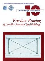
Erection Bracing of Low-Rise Structural Steel Buildings phần 5 pps
Bạn đang xem bản rút gọn của tài liệu. Xem và tải ngay bản đầy đủ của tài liệu tại đây (145.19 KB, 10 trang )
Column: 1(40)25 = 1,000 lbs.
Beams: 2(35)40(0.5) = 1,400 lbs.
Girders: 2(68)40(0.5) = 2,720 lbs.
Roof framing (40)40(5) = 8.000 lbs.
Total = 13,120 lbs. = 13.1 kips
Gravity load: 13.1 kips lbs.
Wind vertical component: 5.9 kips
Net compression on anchor rods: 7.2 kips
Using load factors per the AISC LRFD Specification:
P
u
= 0.9D 1.3W=0.9 (13.1)-1.3 (5.9) = 4.1 kips
(compression)
P
u
= 1.2D-1.3W= 1.2 (13.1) -1.3 (5.9) = 8.1 kips
(compression)
V
u
= 1.3(W) = 1.3 (9.4) = 12.2 kips
Check resistance of (4) 1 in. diameter anchor rods.
Grout thickness is 3 in. Anchor rods have heavy hex lev-
eling nuts and 3/8 in. plate washers. Anchors are spaced
at 10 in. centers and are embedded 12 in.
Anchor rods: ASTM A36
Concrete: f'
c
= 3500 psi
Force to each anchor rod:
Axial: 8.1 ÷ 4 = 2.0 kips (compression)
Shear: 12.2 ÷ 4 = 3.1 kips
Using procedure from Section 4.2.4 for axial load:
k = 1.0
A
b
= 0.7854in.
2
= 3-(0.375+1)= 1.625 in.
r = 0.25 (d) = 0.25(1) = 0.25 in.
kL/r = 1(1.625)70.25 = 6.5
= 30.53 ksi per LRFD Table 3-36
Bending:
Moment arm = 0.5 (3 - (0.375 + 1)) = 0.81 in.
M
u
= 3.1 (0.81) = 2478 in lb. = 2.5 in kip
= 0.9 (36) 0.167 = 5.4 in kip
where
Z
x
= d
3
/6 = (1)
3
/6 = 0.167 in.
3
F
y
= 36 ksi
= 0.9
Using LRFD Eq. H1-16
0.50
< 1.0
o.k.
It should be noted that the anchor rods must be adequate-
ly developed to resist a punch through failure per Sec-
tion 4.2.5.
Design strength in shear using the procedure and nota-
tion in UBC-94:
V
ss
=
0.75 A
b
f'
s
V
ss
= 0.75(0.785)58 = 34.1 kips
0.85(800)(0.785)(1)(3500)
1/2
(1/1000)
=31.5 kips
V
u
= 3.1 kips
3.1
<31.5
o.k.
In this example the loads, load factors and load com-
binations resulted in a net compressive force on the an-
chor rods. To illustrate the calculation procedure, using
a net tension force the example continues using a P
u
=
8.1 kips tension. All other design parameters remain un-
changed.
Force to each anchor rod:
Axial: 8.1 ÷ 4 = 2.0 kips (tension)
Shear: 12.2 ÷ 4 = 3.1 kips
Using the procedure and notation in UBC-94
Design strength in tension:
where
1.0 for normal weight concrete
(2.8 A
s
+ 4A
t
) represents the surface of a truncated fail-
ure surface cone as presented elsewhere in this guide as:
where
37
© 2003 by American Institute of Steel Construction, Inc. All rights reserved.
This publication or any part thereof must not be reproduced in any form without permission of the publisher.
the embedment depth, in.
1.7 (rod diameter)
spacing, in.
(12+1.7/2)
2
+4(12+ 1.7/2)(10+1.7)- (1.7)
2
706.5 in.
2
0.85 (1) 706.5 (4) (3500)
1/2
(1/1000)
142.1 kips
142.1 ÷ 4 = 35.5 kips per rod
Design strength in shear:
0.75(0.785)58 = 34.1 kips
0.85 (800) (0.785) (1) (3500) (1/1000)
= 31.5 kips
Combining tension and shear per UBC-94, para.
1925.3.4
This establishes the resistance based on the anchor rod
strength and concrete strength at the level of the con-
crete. The rods must also be checked in bending.
Rod in bending and tension.
Moment arm = 0.5(3-1-0.375) = 0.81 in.
3050 x 0.81 in. = 2478 in lb.
= 2.5 in kip
0.9(36)0.167 = 5.4in kip
where
Axial tension is as calculated above.
Combining bending and tension per AISC:
This result can also be found in Table 23 where an allow-
able cable force of 18,114 pounds is given for this geom-
etry, anchor rod and grout combination. This value ex-
ceeds the actual cable force of 11,075 pounds.
Example 5-5
Check the column anchor rods for the forces induced by
the diagonal cable force determined in Design Example
5-1, using a bent plate Type B attachment.
This check is the same as that of Example 5-4 except
that the vertical force component is carried by only the
anchor rod to which the bent plate anchor is secured.
The design for bending and shear is the same.
Axial force: 8.1 kips (one anchor rod only.)
Using the procedure in UBC-94 and section 4.2.5. of
this guide.
Design strength in tension.
40.9 kips as before
where
=
0.85
= 1.0
where
the embedment depth, in.
1.7 (rod diameter)
516.5
in.
2
0.85 (1) 516.5 (4) (3500)
1/2
(1/1000)
103.9 kips
In this case the rod strength governs. The shear strength
is as in Example 5-4 and thus the interaction per
UBC-94 is as follows:
Checking the rod in bending and tension, the bending is
as before. The tension is carried by only one rod.
8.1 kips
40.9 kips, as before
2.5 in kips, as before
5.4 in kips, as before
Combining bending and tension per AISC:
38
© 2003 by American Institute of Steel Construction, Inc. All rights reserved.
This publication or any part thereof must not be reproduced in any form without permission of the publisher.
This result can also be found in Table 25 where an allow-
able cable force of 13,471 pounds is given for this geom-
etry, anchor rod and grout combination. This value ex-
ceeds the actual cable force of 11,075 pounds.
The footing must also be evaluated to determine its re-
sistance to the cable diagonal force. In this situation the
footing can be evaluated using the procedure developed
for deadmen, which follows.
5.3 Design of Deadmen
On occasion the erector must anchor cable bracing
to a "deadman". A deadman may be constructed on top
of the ground, near the ground surface, or at any depth
within the soil. They may be short in length or continu-
ous.
5.3.1 Surface Deadmen
The simplest form of a deadman is a mass of dead
weight sitting on top of the ground surface. A block of
concrete is generally used. The anchor resistance pro-
vided by such a deadman is dependent upon the angle
that the bracing cable makes with the deadman and the
location of the bracing cable attachment relative to the
center of gravity of the deadman. As the angle of the
bracing from the horizontal becomes greater, the resis-
tance of the deadman to horizontal sliding reduces.
The resistance to sliding equals the total weight of
the deadman less the upward force from the bracing
cable, times the coefficient of friction between the dead-
man and the soil. A coefficient of friction of 0.5 is gen-
erally used. In equation format:
Eq.5-6
where
= the nominal horizontal resistance of the dead-
man
= the weight of the deadman, lbs.
P = the required brace force, lbs.
0.5 = the coefficient of friction
Using a factor of safety of 1.5 for sliding the allowable
resistance is thus:
Eq. 5-7
In addition to satisfying Eq. 5-7 the overturning resis-
tance of the deadman must be checked. This can be ac-
complished by taking moments about the top of the
deadman. A factor of safety of 1.5 is commonly used for
overturning.
5.3.2 Short Deadmen Near Ground Surface
On occasion a deadman may also be buried into the
soil. The deadman must be designed to resist the verti-
cal and horizontal force exerted by the bracing system.
The vertical force is resisted by the weight of the dead-
man. The required weight equals:
where
the weight of the deadman, lbs.
the bracing force, lbs.
the angle measured from the horizontal of the
bracing cable, degrees
1.5 = the factor of safety used for uplift
The horizontal resistance varies depending upon the soil
condition at the site.
Granular Soils
Based on soil mechanics principles the total resis-
tance to sliding can be expressed as:
Eq. 5-9
where
the total nominal horizontal resistance, lbs.
length of the deadman, perpendicular to the
force, ft.
total passive earth pressure, lbs. per lineal ft.
total active earth pressure, lbs. per lineal ft.
coefficient of earth pressure at rest
unit density of the soil, pcf
coefficient of passive earth pressure
coefficient of active earth pressure
depth of the deadman in soil, ft.
angle of internal friction for the soil, degrees
The following values may be used except in unusual sit-
uations:
39
© 2003 by American Institute of Steel Construction, Inc. All rights reserved.
This publication or any part thereof must not be reproduced in any form without permission of the publisher.
0.6
Thus,
Eq. 5-10
Using a factor of safety of 1.5,
Eq.
5-11
where
the allowable resisting force.
Cohesive Soils
For cohesive soils the ultimate horizontal resis-
tance provided by the deadman can be calculated from
the following equation:
Eq.
5-12
where
the length of the deadman, ft.
total passive earth pressure, lbs. per lineal ft.
total active earth pressure, lbs. per lineal ft.
the unconfined compression strength of the soil,
psf
H = depth of the deadman, ft.
The following values may be used in this equation:
1500 psf (usually conservative)
Thus,
Eq.
5-13
Using a factor of safety of 1.5,
Eq.
5-14
Example 5-6
Check footing as surface deadman.
Footing: 6'-0" x 6'-0" x l'-6"
Soil: Granular type
Calculate weight of footing:
W
d
= 6x 6 x 1.50 x 0.150 = 8.1 kips
Calculate weight of frame
Column: 25(40) = 1,000 lbs.
Beams: 40(35) = 1,400 lbs.
Girders: 40(68) = 2,720 lbs.
Framing: 40(40)5 = 8.000 lbs.
Total 13,120 lbs. = 13.1 kips
(Eq.
5-6)
W
d
= 8.1 + 13.1=21.2 kips
From Example 5-1
= 11.1 kips
= 32°
R
n
= 0.5 (21.2 -(11.1 (sin 32°)) = 7.7 kips
Using a factor of safety of 1.5,
0.67(R
n
) = 0.67(7.7) = 5.1 kips
11.1 (cos 32°) = 9.4 kips
5.1 < 9.4
n.g.
Check footing as deadman in ground:
(Eq.5-11)
L = length of deadman, ft.
H = depth of deadman, ft.
213 (6) 1.5
2
+ 15 (1.5)
3
= 2909 lbs. - 2.9 kips
A thicker footing is required
= 9.4 kips
Solving for H
9400 = 213(6)x
2
+ 15(x)
3
x = 2.68ft.
Try a footing: 6'-0" x 6'-0" x 2'-9"
Check overturning. The anchor is attached to the foot-
ing top at the center of the footing:
Overturning moment:
(11.1 sin 32°)(3) + (11.1 cos 32°)(2.75) = 43.5 ft kips
Resisting moment:
(6)(6)(2.75)(0.150)(3) + 13.1(3) = 83.8 ft kips
Factor of Safety = 89.2/46.6 = 1.9 > 1.5 o.k.
In the foregoing example the size of the footing required
to resist the diagonal cable force was substantially larger
than would be common in the building described else-
where in the examples. The example indicates that the
footing resistance may often be the limiting factor. The
schedule of a construction project may not allow rede-
sign and rebidding to account for changes due to the
erection bracing. In this event the footing and founda-
tions must be taken as a limiting constraint to the erec-
tion bracing design. This condition will result in an in-
crease in the number of diagonal bracing cables
required.
40
© 2003 by American Institute of Steel Construction, Inc. All rights reserved.
This publication or any part thereof must not be reproduced in any form without permission of the publisher.
PART 2
DETERMINATION OF BRACING
REQUIREMENTS USING PRE-
SCRIPTIVE REQUIREMENTS
6. INTRODUCTION TO PART 2
Part 2 presents a series of prescriptive requirements
which if followed eliminates the need to use the calcula-
tion methods, thus simplifying the determination of the
temporary bracing required. The prescriptive require-
ments are:
1. Requirements relating to the permanent
construction, such as bay size, frame layout,
anchor rod characteristics and foundation
characteristics.
2. Requirements relating to the temporary brac-
ing requirements and minimum requirements
for the sequence of erection and installation of
temporary bracing.
These prescriptive requirements are grouped by ex-
posure category and by size. An illustrative example of
an erection plan incorporating the prescriptive require-
ments is also presented.
7. PRESCRIPTIVE REQUIREMENTS
7.1 Prescriptive Requirements for the Permanent
Construction
Tables 7.1 through 7.24 present prescriptive require-
ments which limit features of the permanent construc-
tion. The features which are critical are:
1. Bay size.
2. Column height.
3. Column size.
4. Base plate thickness.
5. Pier size.
6. Footing size.
7. Column setting type.
8. Anchor rod diameter.
9. Anchor rod pattern.
10. Anchor rod termination, hooked or nutted.
11. Anchor rod embedment.
12. Anchor rod cover below bottom end.
Three bay sizes are presented: 30-foot, 40-foot
and 50-foot. The column heights presented are:
15-foot, 30-foot and 45-foot. Two types of settings are
presented. The first type loads the anchor rods in com-
pression. This type of base uses leveling nuts. The se-
cond type are those bases which do not transmit com-
pression forces to the anchor rods, namely, pre-grouted
setting plates, shims and anchor rods with an additional
nut installed just below the top surface of the concrete,
as illustrated in Figure 4.17.
If the conditions upon which these tables are based
are present in the construction and the erector follows
the requirements for erection sequence and cable brac-
ing, then no separate analysis for the determination of
temporary supports is required. Both single story and
two story structures are addressed in the tables.
The tables are based on the following parameters:
1. Both wind exposure categories B and C are tab-
ulated. The exposure category used is to be
that for which the structure is designed.
2. The design wind pressures are those associated
with an 80 mph basic wind speed. The tables
are not be valid for greater speeds. The design
wind speed has been reduced for a six week (or
less) exposure duration as described in para-
graph 3.2.1 of the text. Also a design wind
speed of 35 mph has been used for elements
which are exposed to the wind for a period of
no more than twenty-four hours. This includes
individual columns supported on their bases
and individual beam/column pairs prior to the
installation of tie members. A single row of
beams and columns supported only by their
bases would not meet the limitations of these
tables. In the case of a two story column both
the upper and lower beams may be erected fol-
lowing the limitations cited above for beam/
column pairs.
3. In calculating wind forces on frames, 24 inch
deep solid web members and 48 inch deep open
web members were used. Member depths on
the frame lines exceeding these maximums
would invalidate the prescriptive require-
ments. Also, 12 inch deep columns were used.
Greater depth columns would not be valid.
4. With regard to the footings and piers the fol-
lowing parameters are used. The concrete
strength is 3000 psi. This strength is the
28-day cylinder strength which may be
achieved in less than 28 days, but must be con-
firmed by test. The area of reinforcement in
the piers must be at least one half of one percent
of the area of the concrete pier. The factor of
safety against overturning and sliding used is
1.5. In the determination of uplift and over-
41
© 2003 by American Institute of Steel Construction, Inc. All rights reserved.
This publication or any part thereof must not be reproduced in any form without permission of the publisher.
turning resistance, a dead load equal to 4 psf
over the column tributary area plus the footing
weight is used.
5. The strength of the column to base plate weld is
based on a fillet weld size of 5/16 inch. The
weld must be made to both sides of each flange
and each side of the web. Lesser weld sizes
and/or extents would require calculations as
presented in Part 1.
6. In several cases, hooked anchor rods may be
used per the tables. It is permissible in these
cases to substitute a headed anchor rod with the
same embedment.
7. In the determination of column base moment
strength for columns with setting plates, a mo-
ment arm equal to one half the bolt spacing
plus one half the column flange width is used.
8. In the determination of the diagonal cable
force to be resisted, the degree of base fixity
provided by the column bases is considered.
This has the effect of reducing the required
cable force to be developed.
9. The tables require the placement of opposing
pair diagonal cable braces in each frame line in
both orthogonal directions. These braces must
be placed in every fourth bay along the frame
lines in Exposure B conditions and in every
third bay in Exposure C conditions.
10. The diagonal cable brace required for the one
story frames presented is a 1/2 inch diameter
wire rope with a minimum nominal breaking
strength of 21,000 pounds. For the two story
frames, a 5/8 inch diameter wire rope with a
minimum nominal breaking strength of 30,000
pounds is required.
11. The wire rope diagonals can be anchored to the
columns with Type A or Type B anchors as il-
lustrated in Figures 5.2.1 and 5.2.2.
Anchor required for one story frames:
Type A:
Plate thickness = in.
L = 3 in.
Weld = 3/16 fillets
Grout thickness = 3 in., maximum
TypeB:
Plate thickness - in.
B = 4 in.
Grout thickness = 2 in., maximum for in.
diameter anchor rods and 3 in., maximum for
diameters greater than in.
Anchor required for two story frames:
Type A:
Plate thickness = in.
L = 4 in.
Weld = in, fillets
Grout thickness = 2 in., maximum for in.
diameter anchor rods and 3 in., maximum for
diameters greater than in.
TypeB:
Plate thickness = in.
B = 5 in.
Grout thickness = 2 in., maximum for in.
diameter anchor rods and 3 in., maximum for
diameters greater than in.
Termination of wire rope can be made by wrap-
ping, if the limitations presented in paragraph
5.2 are followed.
7.2 Prescriptive Requirements for Erection Se-
quence and Diagonal Bracing
In addition to the prescriptive requirements for the
permanent structure, there are prescriptive require-
ments for erection sequence and diagonal bracing.
Figure 7.1 illustrates an erection plan with diagonal
bracing in specific bays. It also identifies an initial box
from which the erection is to commence. Figures 7.2
through 7.5 illustrate the build out from the initial box.
The pattern of column, girder, column, girder, tie beam,
x-brace is to be repeated as the erection proceeds. This
limitation on sequence is established to restrict the sur-
face of frame exposed to wind when that portion of the
frame is supported solely by the anchor bolts. The se-
quence given above limits the exposure to one column
and one-half of one beam. In a two story frame, the ex-
posure is limited to one column and one -half each of the
upper and lower beams. The number of braced bays, the
size and strength of wire rope to be used and the anchor-
age required for this wire rope are given in Section 7.1
The erection plan in Figure 7.1 illustrates columns,
girders, tie members and temporary x-braces. This plan
is divided into four erection sequences. Figure 7.1 con-
tains features which are solely illustrative and others
which are prescriptive.
The illustrative features are:
1. Proportion of bay: A square bay is shown and
is required for use of the Tables. The dimen-
sion of the bays are the 30-foot, 40-foot, and
50-foot bays as presented in Tables 7.1
through 7.24. Rectangular bays induce a dif-
ferent set of loads, cable forces and angles and
the prescriptive requirements are not valid. If
the structure to be erected has rectangular bays,
the calculation method must be used.
2. Number of bays: An arrangement of five bays
by seven bays is shown. The number of bays in
each direction is not limited.
42
© 2003 by American Institute of Steel Construction, Inc. All rights reserved.
This publication or any part thereof must not be reproduced in any form without permission of the publisher.
3. Columns: A wide flange column is shown.
Pipe and tube columns may also be used.
4. Column orientation: Any arrangement of col-
umn orientations is permitted.
5. Erection sequences: Four (I to IV) erection se-
quences are illustrated. The number and pat-
tern of erection sequences is not limited.
6. Starting point of erection: Erection begins at
the "initial box" in the upper left hand corner of
the plan. The location of the starting point is
not limited; however, at the starting point an
initial box must be formed.
7. Progression from the initial box: The plan and
the supplementary figures illustrate a progres-
sion from the initial box. This progression fol-
lows this sequence: bay 1-2, B-C, bay 1-2,
C-D, bay 2-3, A-B, etc. The progression from
the initial box can follow any order however it
must follow a bay by bay development in
which beam/column pairs are erected followed
by the erection of the tie members followed by
the installation of the temporary x-brace. This
is illustrated in Figure 7.3, which shows an x-
brace installed between columns C/l and C/2
before the erection proceeds to grid line D.
8. Location of x-braces: The plan shows x-
braces in the exterior bay 1-2. It is not required
that x-braces be located in exterior bays unless
it is necessary to meet the prescriptive require-
ments. X-braces must be located per the pre-
scriptive requirements, namely every third or
fourth bay depending on the exposure catego-
ry, on each frame line, on all four sides of the
initial box and in the bays which proceed out-
ward from the initial box (see Figures 7.2-7.5).
9. Use of x-braces: Each opposing cable pair is
shown as an x-brace. The opposing cable pairs
do not necessarily need to be installed as an "x"
except when a single bay is to be braced such as
the four sides of the initial box and the bays
framed out from the initial box (see Figures 7.2
and
7.3).
10. Use of temporary bracing: Figures 7.1 through
7.5 show the use of only temporary bracing.
Permanent bracing may be used; however, this
requires evaluation by the calculation method
(Part 1) to properly determine the interaction
of permanent and temporary bracing.
Lastly, temporary bracing must remain in place un-
til its removal is permitted as provided for in the AISC
Code of Standard Practice.
43
© 2003 by American Institute of Steel Construction, Inc. All rights reserved.
This publication or any part thereof must not be reproduced in any form without permission of the publisher.
Note: Footing thickness given is a minimum which must be
increased to match embedment plus cover in some
cases.
Note: Pier size given is the minimum size required for
strength. A larger pier may be required to match the
column provided.
Note: The anchor rod parameters given are minimums.
Table 7.1 Prescriptive Requirements for
Exposure B, 30 ft. Bays, 15 ft. Column
Height, One Story Frame
Note: Footing thickness given is a minimum which must be
increased to match embedment plus cover in some
cases.
Note: Pier size given is the minimum size required for
strength. A larger pier may be required to match the
column provided.
Note: The anchor rod parameters given are minimums.
Table 7.2 Prescriptive Requirements for
Exposure B, 30 ft. Bays, 30 ft. Column
Height, One Story Frame
44
Exposure Category
Bay Size, ft.
Column Height, ft.
Stories
Column Size
Base Plate, Thickness, in.
Pier Size, in. x in.
Footing Size, ft. x ft. x in.
B
30
15
1
W8X24
0.75
12X12
4.0X4.0X12
Anchor Rods with Leveling Nuts
Anchor Rod, Diameter, in.
Anchor Pattern, in. x in.
Hooked or Nutted
Embedment, in.
Cover Below Anchor, in.
0.75
4X4
3 in. Hook
6
6
Anchor Rods, Base Plate Shimmed or Grouted
Anchor Rod, Diameter, in.
Anchor Pattern, in. x in.
Hooked or Nutted
Embedment, in.
Cover Below Anchor, in.
0.75
4X4
3 in. Hook
6
3
Exposure Category
Bay Size, ft.
Column Height, ft.
Stories
Column Size
Base Plate, Thickness, in.
Pier Size, in. x in.
Footing Size, ft. x ft. x in.
B
30
30
1
W8X31
0.75
12X12
4.5X4.5X12
Anchor Rods with Leveling Nuts
Anchor Rod, Diameter, in.
Anchor Pattern, in. x in.
Hooked or Nutted
Embedment, in.
Cover Below Anchor, in.
0.75
4X4
3 in. Hook
6
6
Anchor Rods, Base Plate Shimmed or Grouted
Anchor Rod, Diameter, in.
Anchor Pattern, in. x in.
Hooked or Nutted
Embedment, in.
Cover Below Anchor, in.
0.75
4X4
3 in. Hook
6
3
© 2003 by American Institute of Steel Construction, Inc. All rights reserved.
This publication or any part thereof must not be reproduced in any form without permission of the publisher.
Exposure Category
Bay Size, ft.
Column Height, ft.
Stories
Column Size
Base Plate, Thickness, in.
Pier Size, in. x in.
Footing Size, ft. x ft. x in.
B
40
30
1
W8X31
0.75
12X12
5.0X5.0X12
Anchor Rods with Leveling Nuts
Anchor Rod, Diameter, in.
Anchor Pattern, in. x in.
Hooked or Nutted
Embedment, in.
Cover Below Anchor, in.
0.875
4X4
3 in. Hook
6
9
Anchor Rods, Base Plate Shimmed or Grouted
Anchor Rod, Diameter, in.
Anchor Pattern, in. x in.
Hooked or Nutted
Embedment, in.
Cover Below Anchor, in.
0.75
4X4
3 in. Hook
6
3
Exposure Category
Bay Size, ft.
Column Height, ft.
Stories
Column Size
Base Plate, Thickness, in.
Pier Size, in. x in.
Footing Size, ft. x ft. x in.
B
40
45
1
W12X65
1.0
12X12
5.5X5.5X17
Anchor Rods with Leveling Nuts
Anchor Rod, Diameter, in.
Anchor Pattern, in. x in.
Hooked or Nutted
Embedment, in.
Cover Below Anchor, in.
1.0
5X5
4 in. Hook
6
9
Anchor Rods, Base Plate Shimmed or Grouted
Anchor Rod, Diameter, in.
Anchor Pattern, in. x in.
Hooked or Nutted
Embedment, in.
Cover Below Anchor, in.
1.0
5X5
3 in. Hook
6
3
Note: Footing thickness given is a minimum which must be
increased to match embedment plus cover in some
cases.
Note: Pier size given is the minimum size required for
strength. A larger pier may be required to match the
column provided.
Note: The anchor rod parameters given are minimums.
Table 7.5 Prescriptive Requirements for
Exposure B, 40 ft. Bays, 30 ft. Column
Height, One Story Frame
Note: Footing thickness given is a minimum which must be
increased to match embedment plus cover in some
cases.
Note: Pier size given is the minimum size required for
strength. A larger pier may be required to match the
column provided.
Note: The anchor rod parameters given are minimums.
Table 7.6 Prescriptive Requirements for
Exposure B, 40 ft. Bays, 45 ft. Column
Height, One Story Frame
46
© 2003 by American Institute of Steel Construction, Inc. All rights reserved.
This publication or any part thereof must not be reproduced in any form without permission of the publisher.