handbook of die design 2nd edition phần 3 docx
Bạn đang xem bản rút gọn của tài liệu. Xem và tải ngay bản đầy đủ của tài liệu tại đây (1.27 MB, 72 trang )
is immersed in the tank as well. When exposed to the shock wave, the part is forced to take
on the shape of its die.
This process may be found useful for all tube-forming processes that alter the tube’s
profile and shape, such as complex forming, bulging, and expanding.
3-4-3 Forming With Explosives
Explosive forming is not really a new process, but very similar to electromagnetic forming
described in Sec. 3-4-1. It has been around for years with differing results. Some consider
it a superb method of manufacturing, others have lost their buildings to it in an explosion.
It is a process in which safety cannot be overemphasized.
The energy, derived from explosives can be of tremendous intensity and the use of such
force for forming processes is certainly tempting.
During the forming process, the explosive material, either in pieces or encapsulated, is
placed in a water-filled tank alongside or within a die with the material to be formed. The
charge, when detonated, prompts release of a great amount of steam and gas during a rela-
tively short time interval. Such an action creates a strong shock wave in the liquid medium,
which affects the part to be formed by forcing it to take on the shape of the die.
Objects suitable for utilization of such manufacturing process are mainly tubes, which
may be bulged, expanded, or squeezed to tight tolerances and formed into uneven shapes.
Metal plates may be drawn to wildest shapes, many of them unattainable otherwise.
3-4-4 Superimposed Vibrations
Ultrasonic waves, when applied to the molten metal, promote the development of addi-
tional currents within its mass, which in turn produce a more effective mixing, which
results in an improved homogeneity of the metal. When applied to the metal as it begins to
METAL STAMPING DIES AND THEIR FUNCTION 143
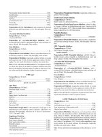
FIGURE 3-58 Section view of a pillar subpress die.
Suchy_CH03.qxd 11/08/05 10:36 AM Page 143
Downloaded from Digital Engineering Library @ McGraw-Hill (www.digitalengineeringlibrary.com)
Copyright © 2004 The McGraw-Hill Companies. All rights reserved.
Any use is subject to the Terms of Use as given at the website.
METAL STAMPING DIES AND THEIR FUNCTION
solidify, ultrasound dissolves microfractures, removes gaseous entrapments, and drives out
impurities.
In solidified metals, high-intensity ultrasound repairs the structural defects by bringing
the material into the stage of plastic deformation and rearranging its structure. Application
of ultrasound reduces friction between metal particles, which in turn allows for a free
movement of metal layers with respect to each other. This aids the forming process and
improves homogeneity of the outcome. The speed of the forming is increased as well, with
lessened friction between the material and its tooling, which subsequently decreases the
wear of the latter.
Ultrasound enhances mechanical properties of materials, increases their hardness, pre-
vents structural changes due to deformation, and lowers stresses caused by manufacturing
processes, while improving the quality of the product’s surface. Many brittle materials,
such as bismuth, were possible to form only after ultrasound was added to the process. This
is explained by the effect of vibrations on a metal crystal, which, under their influence,
develops a series of linear defects, which lower its yield stress range.
When applied to the forming process, ultrasonic vibrations greatly reduce the amount
of force necessary for the alteration of metal.
144 CHAPTER THREE
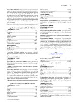
FIGURE 3-59 Cylindrical subpress die.
Suchy_CH03.qxd 11/08/05 10:36 AM Page 144
Downloaded from Digital Engineering Library @ McGraw-Hill (www.digitalengineeringlibrary.com)
Copyright © 2004 The McGraw-Hill Companies. All rights reserved.
Any use is subject to the Terms of Use as given at the website.
METAL STAMPING DIES AND THEIR FUNCTION
However, this type of manufacturing is not widely practiced as yet. Its possible nega-
tive effects on the equipment, on the manufacturing personnel, and perhaps on the fabri-
cated part has not yet been fully assessed.
3-4-5 Lasers and Their Application
Lasers operate on the basis of a concentration of their output to a small area of operation,
approximately 0.002 to 0.010 in. diameter (0.05 to 0.25 mm). One of their advantages is the
absence of contact between the tool (laser) and the workpiece.
The laser cutting process is fast, achieving high quality, burrless edges. The high temper-
ature of the process quickly heats up the material in the path of the laser ray, causing the metal
to melt and evaporate on contact. The surrounding material has no time to respond to such a
sudden wave of heat, which is the reason for the cut surface’s lack of distortion.
3-5 FINEBLANKING
Fineblanking is a special form of blanking, which not only produces finished edges on a cut
part, but also works to close tolerances, attaining a superb consistency over high volumes
of production. Fineblanking is performed in a cutting die, yet it is a process quite similar to
cold extrusion.
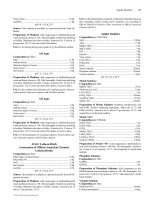
In fineblanking (Fig. 3-60), the material to be pierced is firmly retained by a pressure
ring, which, on descending of the ram, partially enters the material with its grips. The punch
follows down, piercing an opening in the sheet. The pressure of the retaining ring is not
METAL STAMPING DIES AND THEIR FUNCTION 145
FIGURE 3-60 Fineblanking principle.
Suchy_CH03.qxd 11/08/05 10:36 AM Page 145
Downloaded from Digital Engineering Library @ McGraw-Hill (www.digitalengineeringlibrary.com)
Copyright © 2004 The McGraw-Hill Companies. All rights reserved.
Any use is subject to the Terms of Use as given at the website.
METAL STAMPING DIES AND THEIR FUNCTION
immediately released. Instead a counterpressure to a die pad is applied, from the bottom.
This pressure drives the blanked part up, along with the punch. At the die-bushing level,
the pressure ring releases its grip on the metal and the blank can be ejected from the die by
the still-rising bottom pressure pad.
This process uses tight clearances between the punch and the die, which amount to some
0.5 percent of the material thickness. While being taken down and up through the die,
blanks have their cut edges forced into conformity with the surface of the opening. This
smoothes the cut edge, making it even and uniform.
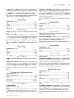
One possible disadvantage can be a tapered edge of blanked parts, which is due to a fric-
tion between the blank and the die opening. This taper is greater with thicker materials, or
with those of higher carbon content. The burr appears on the punch side, while the oppo-
site edge is rounded, as shown in Fig. 3-61.
One definite advantage is the high precision of the work. Openings of 0.125 in. diame-
ter (3.18 mm) can be produced even in 0.187 in. (4.75 mm) thick sheet, with the hole tol-
erance ranging ±0.0004 in. (0.010 mm).
146 CHAPTER THREE
FIGURE 3-61 Fineblanked part.
FIGURE 3-62 Shape of the grip.
Suchy_CH03.qxd 11/08/05 10:36 AM Page 146
Downloaded from Digital Engineering Library @ McGraw-Hill (www.digitalengineeringlibrary.com)
Copyright © 2004 The McGraw-Hill Companies. All rights reserved.
Any use is subject to the Terms of Use as given at the website.
METAL STAMPING DIES AND THEIR FUNCTION
The work-retaining efficiency of grips is relevant to the quality of the cut. Their shape
digs into the material before the punch descends to cut it. This in itself not only provides
for controlled positioning of the sheet under the punch, but also stretches the sheet mater-
ial in all directions, to prevent distortion.
The grips are most often located on the face of a pressure pad, bordering the punch along its
entire shape. With materials thicker than 0.156 in. (4.00 mm), or where rounding of cut edges
is to be kept to a minimum, additional grips may be located on the upper surface of the die.
The shape of the grip, as shown in Fig. 3-62, has two variations: either 45°–45° angles on
both sides, or a 45°–30° angle combination. The height h
1
depends on the material thickness
and its quality. It may vary along these recommended sizes:
h
1
= 0.167t for hard materials
h
1
= 0.333t for softer materials
The distance off the edge of the punch a depends on the height of the grip and its percentile
value should be:
a = (0.6 to 1.2)h
The height of the pressure pad behind the grip’s edge is usually relieved, or:
h
2
= h
1
+ 0.020 in. (0.5 mm)
METAL STAMPING DIES AND THEIR FUNCTION 147
Suchy_CH03.qxd 11/08/05 10:36 AM Page 147
Downloaded from Digital Engineering Library @ McGraw-Hill (www.digitalengineeringlibrary.com)
Copyright © 2004 The McGraw-Hill Companies. All rights reserved.
Any use is subject to the Terms of Use as given at the website.
METAL STAMPING DIES AND THEIR FUNCTION
Suchy_CH03.qxd 11/08/05 10:36 AM Page 148
Downloaded from Digital Engineering Library @ McGraw-Hill (www.digitalengineeringlibrary.com)
Copyright © 2004 The McGraw-Hill Companies. All rights reserved.
Any use is subject to the Terms of Use as given at the website.
METAL STAMPING DIES AND THEIR FUNCTION
CHAPTER 4
149
METAL STAMPING DIES,
THEIR CONSTRUCTION,
AND ASSEMBLY
4-1 TOLERANCING SYSTEMS
Manufacturing of parts cannot be absolutely precise. If such be the case, the cost of com-
ponents would be horrendous. Already the differences in straightness or flatness, surface
finish, the existence of tooling marks or tooling grooves, burrs, chips, and similar, can ren-
der the component unacceptable by too harsh a standard.
Yet, all these discrepancies can sometimes be present and for this reason designers and
manufacturers devised a certain area of benevolent acceptance, called a tolerance range.
This tolerance range specifies the amount of deviation a part can possess and still be accept-
able and function well within an assembly.
Different manufacturing fields use a different tolerance ranges. Where ±0.031 in. (0.79 mm)
can be unacceptable in die work, the same tolerance range is too tight for, let us say, in steel
constructions.
For comparison, quite precise tolerances for glass cutting are:
x.xxx ±0.015 in. x.xx ±0.031 in. fractions ±0.062 in.
x.xx ±0.40 mm x.x ±0.80 mm x ±1.5 mm
Minimal tolerances in woodworking, where NC equipment is utilized, are approxi-
mately:
x.xxx ±0.062 in. x.xx ±0.125 in. fractions ±0.25 in. and more
x.xx ±1.5 mm x.x ±3.2 mm x ±6.5 mm
Every manufacturing field adjusts the tolerance ranges to suit its needs. The fits, how-
ever, are a rather different story, as they always involve two parts, assembled together. Here
the tolerance range must be somewhat standardized and often quite precise. After all, we
are not fitting wooden shafts into openings drilled through glass.
Suchy_CH04.qxd 11/08/05 10:49 AM Page 149
Downloaded from Digital Engineering Library @ McGraw-Hill (www.digitalengineeringlibrary.com)
Copyright © 2004 The McGraw-Hill Companies. All rights reserved.
Any use is subject to the Terms of Use as given at the website.
Source: HANDBOOK OF DIE DESIGN
4-1-1 Types of Fits in Assembly of Parts
The inch-based measuring system has one great advantage––it may establish several
layers of dimensions for easy application of tolerances. In die design, we most often
have:
x.xxx ±0.005 in.
x.xx ±0.010 in.
x.x ±0.015 in.
Fractions ±0.031 in.
which translates into metric system’s three layers only roughly, as follows:
x.xx ±0.13 mm
x.x ±0.25 mm
x ±0.40 mm
These tolerance ranges are rather common in metal fabricating field.
The general range of tolerances, as published by the American Standards Association in
1925 (ASA Standard B4a 1925) runs as shown in Table 4-1.
The use of this table is based on the hole dimension being the nominal size, toleranced
on the plus side, with negative tolerance range equal to zero.
The shaft is handled in the opposite way, its tolerance ranges being negative, with plus
tolerance equal to zero.
However, we will discuss the current American shop practice with regard to toleranc-
ing, later in this chapter.
In metric environment, the basic representation (IT) of ISO tolerancing system comes
in eighteen levels of accuracy. For levels IT 5 through IT 16, a simple formula can be
used,
(4-1)
iDD= 0 45 0 001
3
. +.
150 CHAPTER FOUR
TABLE 4-1 Tolerance Ranges Per ASA Std. B4a-1925
Hole Shaft
Class of fit Clearance Interference tolerance tolerance
1. Loose fit 0.0025 +0.0025 −0.0025
2. Free fit 0.0014 +0.0013 −0.0013
3. Medium fit 0.0009 +0.0008 −0.0008
4. Snug fit 0.0000 +0.0006 −0.0004
5. Wringing 0.0000 +0.0006 +0.0004
6. Tight 0.00025D +0.0006 +0.0006
7. Medium force 0.0005D +0.0006 +0.0006
8. Heavy force 0.001D +0.0006 +0.0006
D
3
D
3
D
3
D
3
D
3
D
3
D
3
D
3
D
3
D
3
D
3
D
3
D
2
3
D
3
D
3
D
2
3
D
3
D
3
D
2
3
Suchy_CH04.qxd 11/08/05 10:49 AM Page 150
Downloaded from Digital Engineering Library @ McGraw-Hill (www.digitalengineeringlibrary.com)
Copyright © 2004 The McGraw-Hill Companies. All rights reserved.
Any use is subject to the Terms of Use as given at the website.
METAL STAMPING DIES, THEIR CONSTRUCTION, AND ASSEMBLY
where D is the geometric center with respect to all combined tolerance ranges, in. or mm
and i is the unit of tolerance, in micrometers (µm).
The upper allowable deviation is described as es or ES. This is the difference between the
given basic diameter and its maximum deviation from this number. The lower deviation is
ei or EI, and it is the difference between the basic diameter and the lower tolerance range.
Both these abbreviations are taken from French, where es/ES is described as écart
superieur and ei/EI is écart inferieur.
The relationship between the two variations applies as follows. Notice the differentia-
tion between shafts and holes by assigning capital letters to the latter.
For shafts ei = es − IT
es = ei + IT
For holes ES = EI + IT
EI = ES − IT
where IT is the basic tolerance range. Selected IT values are given in Table 4-2.
Every punch or die, or any other shape of an object to be mounted per specific require-
ments, is considered a shaft in this description. The same way, every opening of any shape
is considered a hole.
The dimensional variations described above are used as alphabetically/numerically
coded. These values are applied to the holes and shafts in the following manner:
For shafts, a through h = upper tolerance range, es
j through z = lower tolerance range, ei
For holes, A through H = lower tolerance range, EI
J through Z = upper tolerance range, ES
Tolerance ranges A & a and Z & z present the widest differences of the whole arrangement.
They vary the most from the zero-middle line and this way they allow for the loosest fits.
The closer to the zero line, the tighter the dimensional tolerances become. The zero value
of tolerance ranges can be observed with J & j denominations, where their deviations in
either direction are equal and therefore they cancel each other out.
Some recommended shaft/hole variations are presented in Table 4-3. Table 4-4 depicts
the actual values of selected tolerance ranges.
METAL STAMPING DIES, THEIR CONSTRUCTION, AND ASSEMBLY 151
TABLE 4-2 Selected Basic Tolerance Range (IT) Values (Metric)
Dimension range Basic tolerance range in micrometers (µm)
(mm) Levels of accuracy
From To 1 2 3 4 5
3 6 1 1.5 2.5 4 5
6 10 1 1.5 2.5 4 6
10 18 1.2 2 3 5 8
18 30 1.5 2.5 4 6 9
30 50 1.5 2.5 4 7 11
Suchy_CH04.qxd 11/08/05 10:49 AM Page 151
Downloaded from Digital Engineering Library @ McGraw-Hill (www.digitalengineeringlibrary.com)
Copyright © 2004 The McGraw-Hill Companies. All rights reserved.
Any use is subject to the Terms of Use as given at the website.
METAL STAMPING DIES, THEIR CONSTRUCTION, AND ASSEMBLY
152 CHAPTER FOUR
TABLE 4-3 Some Generally Recommended Metric Tolerance Ranges for Shafts
and Openings
Shaft Opening
h6 D8 E8 F8 G7 H7 J7 K7 M7 N7
h7 H8 J8 K8 M8 N8
h8 D9 E8 F9–F8 H8
h9 D10–D9 E8 F9–F8 H9–H8
h11 D11 H11
Opening Shaft
H6 f6 g5 h5 j5 k5 m5 n5
H7 d8 e8 f7 g6 h6 j6 k6 m6 n6
H8 d10–d9 e9 f9–f8 h9–h7 j7 k7 m7 n7
H10 h10–h9
H11 d11 h11
TABLE 4-4 Selected Basic Tolerance Deviations (Metric)
Shaft (mm) Upper deviation, es (micrometers)
From To defghj
36−30 −20 −10 −40±IT/2
610−40 −25 −13 −50±IT/2
10 18 −50 −32 −16 −60±IT/2
18 30 −65 −40 −20 −70±IT/2
30 50 −80 −50 −25 −90±IT/2
Upper
Opening deviation, ES
(mm) Lower deviation, EI (micrometers) (micrometers)
From To DEFGHJ J
36+30 +20 +10 +40±IT/2 +5 to +10
610+40 +25 +13 +50±IT/2 +5 to +12
10 18 +50 +32 +16 +60±IT/2 +6 to +15
18 30 +65 +40 +20 +70±IT/2 +8 to +20
30 50 +80 +50 +25 +90±IT/2 +10 to +24
Suchy_CH04.qxd 11/08/05 10:49 AM Page 152
Downloaded from Digital Engineering Library @ McGraw-Hill (www.digitalengineeringlibrary.com)
Copyright © 2004 The McGraw-Hill Companies. All rights reserved.
Any use is subject to the Terms of Use as given at the website.
METAL STAMPING DIES, THEIR CONSTRUCTION, AND ASSEMBLY
4-2 DIE COMPONENTS, THEIR FABRICATION,
AND ASSEMBLY
A die, as mounted in the press, is a complex-action mechanism, producing parts in prede-
termined sequence. The lower half of the die, mounted on the lower die shoe, is firmly
attached to the press bed, while the upper portion is bolted to the ram, sliding up and down
along with it.
Aside from an upper and lower die shoe, every die consists of several other blocks,
which hold or support the punches, dies, bushings, inserts, and other elements.
The die in Fig. 4-1 has several piercing punches with the last punch being the blanking
station. All punches are assembled into a block called a punch plate, which is separated
from the upper die shoe by a backup plate. Backup plates protect the die shoe from the
effect of forces generated during the operation of the die. These plates are made of hard-
ened steel, usually
3
/
8
in. (10 mm) thick, with a
1
/
2
in. (15 mm) exception for heavy work.
The stripper, shown in Fig. 4-1, is stationary, meaning that it does not ride along with
the upper half of the die, instead it is firmly attached to the die block. Usually a milled chan-
nel for guidance of the metal strip is produced in its bottom surface for that purpose.
METAL STAMPING DIES, THEIR CONSTRUCTION, AND ASSEMBLY 153
FIGURE 4-1 Progressive die.
Suchy_CH04.qxd 11/09/05 6:39 PM Page 153
Downloaded from Digital Engineering Library @ McGraw-Hill (www.digitalengineeringlibrary.com)
Copyright © 2004 The McGraw-Hill Companies. All rights reserved.
Any use is subject to the Terms of Use as given at the website.
METAL STAMPING DIES, THEIR CONSTRUCTION, AND ASSEMBLY
A stripper prevents the piercings from sticking to punches. It also restrains the rest of
the strip from moving along with the upper half of the die by keeping it positioned on the
face of a die block.
The die block contains all bushings, forming dies, or cutting inserts. It is supported by
another backup plate positioned between this block and the lower die shoe.
All cutting, forming, and other material-altering punches and dies are assembled into
their respective blocks using two methods of attachment: Either their body diameter D is
press-fit within the block, with their heads remaining loose, or their head diameter is press-
fitted, while the body remains loose.
As it often happens with progressive dies, there is not much that can be ascertained
just by looking at the two opened halves of the tool. Only on scrutinizing the strip or
strip layout, by comparing it to the cross-section of the die, and by studying details of
punches and bushings, we can discover what this tool is really doing and how it is pro-
ducing producing high-quality, close-toleranced parts each time the ram of the press
slides down.
Majority of such work is done by components of the die, which are punches, die but-
tons, forming blocks, cutoff shears, special arrangements, and others. The die blocks, die
shoes, strippers, pressure pads and similar, are but supportive elements, which contain,
guide, or protect the active segments of the assembly. Naturally, the alignment of these
components is of crucial importance. And so is their location within the die sequence, their
precision fit, perpendicularity, type of steel and hardness, surface finish, to name but a few
influential factors.
A few pointers on the fabrication and assembly of die components are added below.
4-2-1 Punches
Punches and dies are the most basic components of every die. Their bodies and shapes can
be Electro Discharge Machined (EDM’d) from a block or blank, or from a bar stock or
other materials. The material these tooling elements are made from is of a great importance,
not only for its hardness and ductility, but for its behavior in production, resistance to
galling, resistance to changes in material structure due to heat, frequency of sharpening,
and the like.
Every punch and die, when assembled together, must fit exactly; there is no allo-
wance for a slight shift here or there. With a small misalignment, great differences in
punch and die clearances can be generated, which, given the time, will certainly exert a
detrimental effect on the whole die, not talking about quantities of less-than-perfect
parts such a tool can produce. We should bear in mind that dies are but small, automated
production systems. As such, dies are capable of producing numerous perfect parts per
hour. But at the same rate, they can produce rejects, should something within their
design, construction, or assembly go wrong.
A sample of a typical punch, its dimensioning and tolerances is shown in Fig. 4-2.
Notice the diameter of the cutting portion P is quite precise. This dimension is always that
of the opening to be pierced. The cutting tolerance is added to the die opening.
Mounting of punches is evaluated in Fig. 4-3 with respect to the two mounting techniques
already described: Either the shank is press-fit within the block while the head is loosely con-
tained in the counterbore (Fig. 4-3a), or the head is press fit and the shank is loose (Fig. 4-3b).
The second method of mounting is reserved for special instances, whereas the first method is
commonly used for mounting of majority punches.
The proper length of a punch has a considerable effect on the overall performance of the
die. With too long punches, the compressive stress on them may be excessive, resulting in
154 CHAPTER FOUR
Suchy_CH04.qxd 11/08/05 10:49 AM Page 154
Downloaded from Digital Engineering Library @ McGraw-Hill (www.digitalengineeringlibrary.com)
Copyright © 2004 The McGraw-Hill Companies. All rights reserved.
Any use is subject to the Terms of Use as given at the website.
METAL STAMPING DIES, THEIR CONSTRUCTION, AND ASSEMBLY
frequent breakages. The maximum length of a punch may be calculated with the aid of the
formula
(4-2)
where L = maximum length of the punch
d = punch diameter
t = thickness of punched material
E = modulus of elasticity
S = shear stress of the material
The ratio of the punch diameter to the stock thickness must satisfy the condition
Smaller ratios are generally not recommended in sheet-metal practice, not that smaller
holes cannot be produced, but their method of manufacture is much more complicated.
d
t
= 1.10 minimum
L
dEd
St
=
π
8
METAL STAMPING DIES, THEIR CONSTRUCTION, AND ASSEMBLY 155
FIGURE 4-2 Detail of a punch.
Suchy_CH04.qxd 11/08/05 10:49 AM Page 155
Downloaded from Digital Engineering Library @ McGraw-Hill (www.digitalengineeringlibrary.com)
Copyright © 2004 The McGraw-Hill Companies. All rights reserved.
Any use is subject to the Terms of Use as given at the website.
METAL STAMPING DIES, THEIR CONSTRUCTION, AND ASSEMBLY
156 CHAPTER FOUR
FIGURE 4-3 Mounting of punches.
Suchy_CH04.qxd 11/08/05 10:49 AM Page 156
Downloaded from Digital Engineering Library @ McGraw-Hill (www.digitalengineeringlibrary.com)
Copyright © 2004 The McGraw-Hill Companies. All rights reserved.
Any use is subject to the Terms of Use as given at the website.
METAL STAMPING DIES, THEIR CONSTRUCTION, AND ASSEMBLY
Better punch materials with higher compressive strengths may be required, and additional
stripping and tool-guiding arrangements may be needed, along with greater clearances
between the punch and die.
Other restrictive conditions, dealing with similar situations, may be followed up in
Sec. 6-8.
When assembling the punch into a punch plate, or the die into the die block, a certain
tightness of fits is mandatory. After all, the punch cannot jump up and down in the open-
ing with every stroke of a press. The tightness, or rather interference between the tool shank
and its opening, is called press fit and in American shops it follows specific guidelines,
where the maximum amount of interference between any two objects is to be 0.0014 in.
(0.035 mm). Interferences greater than that will not allow for the assembly of parts.
Sometimes, the extremes have to be resorted to, such as heating the block and freezing
the punch, as the punch is always slightly larger than the opening. Pushing the punch or die
into an opening with a small press is another method of assembly.
With 0.014 in. (0.035 mm) total indicator reading (T.I.R.), die components will suc-
cumb to the harsh assembly conditions and will be well-seated in their respectable open-
ings. With respect to the above, the punch body diameter, including its highest amount of
tolerance (see Fig. 4-3a) will be
1.0000 + 0.0004 = 1.0004 in.
(25.400 + 0.010 = 25.410 mm)
The punch plate opening into which the punch will be assembled (here we subtract the
higher of the two tolerance amounts) is
0.9995 − 0.0004 = 0.9991 in.
(25.387 − 0.010 = 25.377 mm)
The total variation between these two numbers is
1.0004 − 0.9991 = 0.0013 in.
(25.410 − 25.377 = 0.033 mm)
Note: The metric dimensional discrepancy between the recommended variation of 0.035
mm and the calculated variation of 0.033 mm is due to rounding of converted numerical
values.
This interference is acceptable, and yet the ranges of tolerance for the two vital dimen-
sions are not out of the ordinary. Through such evaluation we may assess that if the two
parts were to be made to the fullest extent of their tolerance ranges, they still could be press-
fit together.
Now the lower amount of press-fit scenario has to be assessed, where the minimum
amount of interference between two press-fit objects is 0.0003 in. (0.008 mm). This lower
end of the tolerance range should be evaluated as well, to provide for a situation where both
parts may be made to their smallest possible press-fit dimensions.
The punch size, including the lower value of the two tolerance ranges, will be
1.000 + 0.0002 = 1.0002 in.
(25.400 + 0.005 = 25.405 mm)
The punch plate opening minus the smaller amount of tolerance is
0.9995 − 0.0002 = 0.9993 in.
(25.387 − 0.005 = 25.382 mm)
METAL STAMPING DIES, THEIR CONSTRUCTION, AND ASSEMBLY 157
Suchy_CH04.qxd 11/08/05 1:57 AM Page 157
Downloaded from Digital Engineering Library @ McGraw-Hill (www.digitalengineeringlibrary.com)
Copyright © 2004 The McGraw-Hill Companies. All rights reserved.
Any use is subject to the Terms of Use as given at the website.
METAL STAMPING DIES, THEIR CONSTRUCTION, AND ASSEMBLY
Subsequently,
1.0002 − 0.9993 = 0.0009 in.
(25.405 − 25.382 = 0.023 mm)
0.0009 in. (0.023 mm) is quite a tight fit, which clearly indicates that the assembly
will be adequately stable. But the absolute minimum of interference, such as that where
no tolerance buildup of any kind will be generated on either of the two parts, must be
judged as well. This condition is obtained by comparing the two basic dimensions as
follows:
1.0000 − 0.9995 = 0.0005 in.
(25.400 − 25.387 = 0.013 mm)
With 0.0005 in. (0.013 mm) being the lowest possible interference and 0.0013 in.
(0.033 mm) being the highest, we have an acceptable level of press fit for the two metal
parts. However, dimensions of actual products are rarely found on either extreme side of
their tolerance range but are rather somewhere in between. Therefore, it is not important in
which section of the tolerance range these parts are made. As long as they are made within
the drawing’s dimensional requirements, they will fit.
The second method of assembly, shown in Fig. 4-3b, should be evaluated the same way.
Here we control the tolerance buildup of the press-fitted punch head. Its size and tolerances
were purposely made the same so that the equality of both methods can be easily demon-
strated.
The height of the punch head in this type of assembly is usually greater, since the
increased length of the press-fit area is vital to the stability of the tool.
In assembly, the process of inserting punches and dies into their openings in blocks is
aided by the presence of a lead. The lead is a
1
/
4
in. wide band on the circumference of the
punch shank (or die), which is slightly smaller in diameter, for an easy entry of the large
part into the smaller, press-fit opening.
4-2-1-1 Depth of the Counterbore Versus the Height of the Punch Head. When
comparing the thickness of the punch head to the depth of the counterbored opening, it
is obvious that the metal of the punch head is purposely being allowed to exceed the
height of the block. This is because after all punches are assembled, the whole block is
placed into the surface grinder, where all punch heads are leveled down so that they
will be flushed with the block.
Tolerance ranges for the height of punch head lean toward the plus side, while toler-
ances for the depth of counterbore go in the minus direction.
The height of the punch head in Fig. 4-3a, is dimensioned as
Note: Some values converted to metric are purposely rounded to the nearest 5 or 10, to
comply with the European dimensioning customs.
It can be minimally 0.188 in. (4.75 mm), with its maximum size being 0.198 in. (5.0 mm).
The two tolerance ranges being in the same direction (both plus) indicates that such a
dimension should never slip into the opposite, into minus.
0.188
0.005
0.010
in.
4.75
0.13
0.25
mm
+
+
+
+
158 CHAPTER FOUR
Suchy_CH04.qxd 11/08/05 10:49 AM Page 158
Downloaded from Digital Engineering Library @ McGraw-Hill (www.digitalengineeringlibrary.com)
Copyright © 2004 The McGraw-Hill Companies. All rights reserved.
Any use is subject to the Terms of Use as given at the website.
METAL STAMPING DIES, THEIR CONSTRUCTION, AND ASSEMBLY
The counterbore’s depth begins with the same nominal dimension, toleranced on the
minus side:
Here the opening’s depth can be a maximum of 0.188 in. (4.75 mm), with its minimal
size 0.178 in. (4.50 mm).
The total tolerance buildup between the two parts can be figured out by comparing their
two most extreme dimensions:
0.198 − 0.178 = 0.020 in.
(5.00 − 4.50 = 0.50 mm)
which means that the maximum difference between the height of the punch and the depth
of the pocket can be 0.020 in. (0.51 mm). The minimal difference will be zero, since both
start with the same nominal size, 0.188 in. (4.75 mm).
Another depth-tolerancing method uses slightly tighter tolerance ranges for both the
punch head and its counterbore, with the offset between their basic dimensions. In such a
case, the height of the punch head is
while the depth of the counterbore is automatically lowered some 0.005 in. (0.13 mm) or
0.010 in. (0.25 mm) (the exact amount depends on the manufacturing practice of the par-
ticular shop). The depth of counterbored pocket then becomes
The total tolerance buildup, obtained through comparison of the two most extreme
sizes, will come out as
0.193 − 0.173 = 0.020 in.
(4.88 − 4.37 = 0.51 mm)
The second punch head, shown in Fig. 4-3b, is dimensioned and toleranced similarly.
Its tolerance range has already been tightened.
4-2-1-2 Jektole
®
Punches. Jektole punches are constructed similarly to regular
punches, the difference being a spring-loaded, slug-ejecting pin in their center, as shown in
Fig. 4-4. The pin, continuously forced out by the spring pressure, retreats back into the
punch only on contact with the material during presswork. But as soon as the press-force is
released, the pin springs out, forcing the slug off the punch face.
0 178
0 000
0 005
450
000
013
.
.
.
.
.
.
+
−
+
−
in.
mm
0.188
0.005
0.000
in.
4.75
0.13
0.00
mm
+
−
+
−
0 188
0 005
0 010
475
013
025
.
.
.
.
.
.
−
−
−
−
in.
mm
METAL STAMPING DIES, THEIR CONSTRUCTION, AND ASSEMBLY 159
Suchy_CH04.qxd 11/08/05 10:49 AM Page 159
Downloaded from Digital Engineering Library @ McGraw-Hill (www.digitalengineeringlibrary.com)
Copyright © 2004 The McGraw-Hill Companies. All rights reserved.
Any use is subject to the Terms of Use as given at the website.
METAL STAMPING DIES, THEIR CONSTRUCTION, AND ASSEMBLY
According to the manufacturer, Jektole can use larger tolerance ranges between punches
and dies. Where regular clearances of 5 to 8 percent per side produce holes undersized by
−0.0002 to −0.0005 in. [0.005 − 0.013 mm], Jektole at 10 to 12 percent clearance per side pro-
duce cutouts on the plus side, or +0.0002 to +0.0005 in. [0.005 − 0.013 mm]. Such a generous
clearance between the punch and die opening affects positively the amount of wear and tear of
the cutting punch, for which reason Jektole punches were found producing three times more
cuts than punches with regular clearance. Additionally, the following results were observed:
• Greater rollover surface, while the burnished surface is diminished. The resulting reduc-
tion of compressive stresses is outbalanced by an increase in tensile stresses, which are
needed for the procurement of a cut. The result can be seen in diminished need for sharp-
ening of tooling, reduced breakage, and reduced downtime.
• Lesser bulging of the cut material (see Fig. 4-5). A bulge in the material, where produced,
tightens around the punch and prevents its withdrawal to the point of breaking it, if either
tooling clearance or punch diameter is too small. Jektole punches do not suffer from such an
effect, which is why the wear of punches is reduced to merely one-third of normal-clearance
wear.
• Less friction between the Jektole punch and the material produces less heat, while dimin-
ishing the abrasion effect.
160 CHAPTER FOUR
FIGURE 4-4 Jektole
®
punch. (Technical illustration is reprinted with
permission from Dayton Progress Corp., Dayton, OH.)
FIGURE 4-5 Comparison of clearances: regular punch and Jektole
®
. (Technical illustration is reprinted
with permission from Dayton Progress Corp., Dayton, OH.)
Suchy_CH04.qxd 11/08/05 10:49 AM Page 160
Downloaded from Digital Engineering Library @ McGraw-Hill (www.digitalengineeringlibrary.com)
Copyright © 2004 The McGraw-Hill Companies. All rights reserved.
Any use is subject to the Terms of Use as given at the website.
METAL STAMPING DIES, THEIR CONSTRUCTION, AND ASSEMBLY
• Smaller burr than that created by a 5 percent clearance-per-side tooling.
• 0.0005 to 0.002 in. [0.013 to 0.051 mm] clearance per side for shaving operations.
Additionally, slug-pulling problems, when the slugs are dragged to the die surface by
the retracting punch, were alleviated.
4-2-1-3 Quill Punches. Quill punches (Fig. 4-6c and d) are used for close-spaced open-
ings or cluster tooling. Their heads are quite small, which is the reason why they easily fit
into congested areas. Because of their small body diameter, they are quite fragile; often a
majority of their length has to be contained in a bushing, which not only supports their mass,
but also serves as a guide. When guided, quills can withstand much more stress and strain.
To further support quill’s performance, a guided stripper plate is recommended in tech-
nical literature. A sample of a guided stripper plate is shown in Fig. 4-7.
4-2-1-4 Work Stresses and Their Impact on the Punches. Punches and dies in pro-
duction are exposed to various types of harmful influences, be it stresses from the work
METAL STAMPING DIES, THEIR CONSTRUCTION, AND ASSEMBLY 161
FIGURE 4-6 Miscellaneous punches and dies (dimensions in inches).
Suchy_CH04.qxd 11/08/05 10:49 AM Page 161
Downloaded from Digital Engineering Library @ McGraw-Hill (www.digitalengineeringlibrary.com)
Copyright © 2004 The McGraw-Hill Companies. All rights reserved.
Any use is subject to the Terms of Use as given at the website.
METAL STAMPING DIES, THEIR CONSTRUCTION, AND ASSEMBLY
itself, stresses created by friction, or stresses from compressive loading and impact load-
ing. Stresses caused by impact loading can make a slender punch body quiver, which pre-
disposes it to deflection or even buckling. From such, a permanent misalignment may
result. Where too loose a clearance opening in the stripper pad is counted on to guide the
punch (see Fig. 4-8b), the distortion due to punch vibration can progress unrestricted and
eventually breakage of the punch will result.
162 CHAPTER FOUR
FIGURE 4-7 Guided assembly with quills. (From: Practical Aids For
Experienced Die Engineer, 1980. Reprinted with permission from Arntech
Publishers, Jeffersontown, KY.)
FIGURE 4-8 Guided and unguided punch.
Suchy_CH04.qxd 11/09/05 6:40 PM Page 162
Downloaded from Digital Engineering Library @ McGraw-Hill (www.digitalengineeringlibrary.com)
Copyright © 2004 The McGraw-Hill Companies. All rights reserved.
Any use is subject to the Terms of Use as given at the website.
METAL STAMPING DIES, THEIR CONSTRUCTION, AND ASSEMBLY
Generally, punches of smaller diameters should be guided on their way through the
stripper, for which reason guide bushings are utilized (see Fig. 4-8a). These bushings not
only guide the punch, they are also enforcing its proper alignment, providing support where
and when needed and this way they are protecting the punches from excessive damage and
breakage.
Guide bushings are also recommended where crowding of punches and dies is encoun-
tered. In such a situation, a heavy cutting action alongside a slender punch can send a wave
of cut-stressed material against its body (see Fig. 4-9a), with resulting breakage soon after-
wards. Staggered cutting can help in this scenario.
Another harmful influence can be created by the deflection of material in shear or cut-
off operation, as shown in Fig. 4-9b. Here the pressure of bulging material may attack the
body of the punch and cause damage over the time.
Additional force acting upon the punch during each press stroke is the compressive
force. Sometimes, this force may be of such a magnitude that the punch mass cannot com-
pensate for it and a breakage occurs. Usually, the head of the punch snaps off, with the
breakage line starting where the head joins the body diameter (see Fig. 4-10). When this
happens, we have a choice of several possibilities to investigate (see Fig. 4-11).
Other solutions include the head thickness increase for greater mass of the affected area.
Similarly, the punch body diameter may be enlarged for greater sturdiness. Changes to the
punch face configuration may be of help, especially where a greater punch diameter is con-
cerned. A shear to the cutting surface, allowing the punch to enter the pierced material grad-
ually, may be beneficial (see Fig. 4-12).
The backup plate, where used, should be made of A2 steel, hardened to 40 to 50 HRc.
Oil-hardened steel should be avoided, as the heat treatment causes a greater amount of
warpage in it, which in turn produces inconsistencies in the plate’s flatness. Where the
backup plate is too hard, vibrations may develop in response to the press function, ruining
the punch over time.
4-2-2 Die Button or Die Bushing
Die button, or die bushing is shown in Fig. 4-13 in several variations. The first, a version,
is used and dimensioned for piercing of a single opening, while the b style may produce the
METAL STAMPING DIES, THEIR CONSTRUCTION, AND ASSEMBLY 163
FIGURE 4-9 Distortion in sheet-metal material due to congested cutting. (Technical illustration is
reprinted with permission from Dayton Progress Corp., Dayton, OH.)
Suchy_CH04.qxd 11/08/05 10:50 AM Page 163
Downloaded from Digital Engineering Library @ McGraw-Hill (www.digitalengineeringlibrary.com)
Copyright © 2004 The McGraw-Hill Companies. All rights reserved.
Any use is subject to the Terms of Use as given at the website.
METAL STAMPING DIES, THEIR CONSTRUCTION, AND ASSEMBLY
inner and outer diameter at the same time. The headless die button (Fig. 4-13c) is often used
with a lighter type of work or with parts such as wave washers. The absence of the heel may
reduce the cost of such a bushing’s manufacture and assembly, but the disadvantage of such
an unsecured press fit may be considerable.
Again, the tightness of manufacturing tolerance of the cutting surface may be observed.
Two-tenths of an inch (0.0002 in. or 0.005 mm) variation from the nominal size can be
viewed as precision work.
164 CHAPTER FOUR
FIGURE 4-11 Punch breakage solutions. (Technical illustration is reprinted with permission
from Dayton Progress Corp., Dayton, OH.)
FIGURE 4-10 Head breakage in punches. (Technical illustration is reprinted with permis-
sion from Dayton Progress Corp., Dayton, OH.)
Suchy_CH04.qxd 11/08/05 10:50 AM Page 164
Downloaded from Digital Engineering Library @ McGraw-Hill (www.digitalengineeringlibrary.com)
Copyright © 2004 The McGraw-Hill Companies. All rights reserved.
Any use is subject to the Terms of Use as given at the website.
METAL STAMPING DIES, THEIR CONSTRUCTION, AND ASSEMBLY
METAL STAMPING DIES, THEIR CONSTRUCTION, AND ASSEMBLY 165
FIGURE 4-12 Shear of the punch face.
FIGURE 4-13 Die button.
Suchy_CH04.qxd 11/08/05 10:50 AM Page 165
Downloaded from Digital Engineering Library @ McGraw-Hill (www.digitalengineeringlibrary.com)
Copyright © 2004 The McGraw-Hill Companies. All rights reserved.
Any use is subject to the Terms of Use as given at the website.
METAL STAMPING DIES, THEIR CONSTRUCTION, AND ASSEMBLY
Every die bushing has an opening into which a punch slides when cutting the sheet-
metal material. Such an opening is absolutely straight and precisely finished. It is called the
“die life” (or “land”), and it is the amount of the die height which can be used up for sub-
sequent sharpenings. The height of the die life depends on the number of pieces the die has
to produce and on the number of expected sharpenings during the die button’s existence in
the die.
The height of this area is a debatable subject. In order to prolong the life of a die, a con-
siderable die-life size may be chosen, which may be expected to provide for many sharp-
enings afterward. But, if such a tight portion is excessively long, the piercings, leaving the
die through this channel, may get packed there, perhaps unable to move forward. Such a
condition may endanger not only the punch and die but the whole die assembly as well.
Usually a
1
/
8
in. (3.2 mm) length of die life is specified; rarely a greater size can be
found.
At the other end of the die life the opening enlarges, turning into a clearance hole,
through which the slugs leave the die. Usually this enlargement has a form of draft, most
often in the vicinity of 1.5 to 2° taper.
4-2-2-1 Slug Removal. The three types of slug relief are as shown in Fig. 4-14; a
tapered and counterbored relief with a die life (also called “land”), and a relief that is
tapered through with no die life. Each of these designs has its advantages and disadvan-
tages. For example, the tapered relief controls the movement of flat slugs through the die,
while the counterbored opening allows them to tumble and jam. The jamming of slugs,
their spinning around, bridging against each other and sticking together, can have a detri-
mental effect on the quality of the pierced part and naturally, it is endangering the tooling
as well.
The tapered die relief is more supportive to the cutting edge, and as such, this die often
outlasts counterbored openings. Therefore, it may be summarized that most often, the
improperly chosen or improperly produced slug-relief openings are the main causes of
many slug-related problems.
Counterbored relief opening has its uses elsewhere. It can be successfully utilized to
serve as a stripper, in situations where a cup is pushed past the die life right after being
formed. On retrieval of the punch, the cup cannot follow, being prevented by the counter-
bore’s pocket (see Fig. 4-15). Here the stripping capacity of the counterbored step in the die
is further enhanced by the fact that the cup, or some portions of it, will certainly experience
some springback and will try to increase its upper diameter.
166 CHAPTER FOUR
FIGURE 4-14 Three types of die relief.
Suchy_CH04.qxd 11/08/05 10:50 AM Page 166
Downloaded from Digital Engineering Library @ McGraw-Hill (www.digitalengineeringlibrary.com)
Copyright © 2004 The McGraw-Hill Companies. All rights reserved.
Any use is subject to the Terms of Use as given at the website.
METAL STAMPING DIES, THEIR CONSTRUCTION, AND ASSEMBLY
Another problem in slug removal is often encountered where the slug becomes retained
in the die cavity and does not progress on the way down. It is soon joined by additional
slugs, with which it forms a tightly-packed stack that would not go down. Such column of
piercings can naturally damage the punch and sometimes even split the die button. To elim-
inate this problem, shortening the die life for piercing of thinner materials and evaluating
the punch-die clearance may help. Of advantage may be the use of Jektole punch arrange-
ment described previously, which produces slugs slightly smaller than the die clearance,
allowing them to fall through.
In situations where the die opening is not properly dimensioned and manufactured, the
slugs can become packed tightly, with some of them even varying from the horizontal due to
their uncontrolled movement through the die (see Fig. 4-16). Often such situations result in
punch breakage, with die splitting possible as well.
4-2-2-2 Bazooka
®
Bushing. Another excellent method of slug-removal control is the
Bazooka sleeve, also called Bazooka bushing. It is shown in Figs. 4-17 and 4-18. This slug-
removing sleeve uses compressed shop air to create a vacuum, which is then applied at the
die opening. The vacuum not only prevents slugs from sticking to the punch; it also forces
them to follow the path of suction, afterwards being deposited in a container.
The vacuum system removal is more advantageous than that of removal of slugs with
compressed air, for where compressed air can sometimes make the trimmings and slugs
fly in the wrong direction, vacuum sleeve’s controlled path of slug removal is precisely
specified.
Bazooka vacuum sleeve can be installed directly into the die operating on a maximum
air pressure of 60 psig. Sometimes the sleeve can be contained in a “funnel unit,” as shown
in Fig. 4-19. For more complex slug removal, a vacuum transducer and a cap unit are avail-
able (not shown).
4-2-3 Miscellaneous Notes
Keeping the die function at the optimal levels means not only taking care of all the punches
and dies being properly fabricated and properly mounted. It also involves keeping detailed
METAL STAMPING DIES, THEIR CONSTRUCTION, AND ASSEMBLY 167
FIGURE 4-15 Counterbored
die relief serving as a stripper.
FIGURE 4-16 Packing and dislo-
cation of slugs in a die.
Suchy_CH04.qxd 11/08/05 10:50 AM Page 167
Downloaded from Digital Engineering Library @ McGraw-Hill (www.digitalengineeringlibrary.com)
Copyright © 2004 The McGraw-Hill Companies. All rights reserved.
Any use is subject to the Terms of Use as given at the website.
METAL STAMPING DIES, THEIR CONSTRUCTION, AND ASSEMBLY