handbook of die design 2nd edition phần 6 docx
Bạn đang xem bản rút gọn của tài liệu. Xem và tải ngay bản đầy đủ của tài liệu tại đây (1.18 MB, 72 trang )
As can be expected, not all materials can handle such a rough treatment the reversed
bending presents. This operation introduces a massive amount of strain into the formed sec-
tion (i.e., mainly the corners). This may not only weaken these areas; it will also cause a
greater than ordinary work hardening of the same. Tearing of the metal, wrinkling, and
other defects may result.
8-9 FORMING
Metal forming is a process totally dependent on the influence of outside tensile forces
against the structure of the material. The resulting permanent deformation is called
forming. The force-exerting instrument is the punch, which by pulling the sheet-metal
material along, makes it enter the die, where it is compelled to take upon itself the
impression of the assembly.
The decision if the part is to be formed or drawn is usually based on the evaluation of
its shape and dimensional requirements. Drawing is utilized for those parts made of
thicker materials or for those with vertical (or slightly inclined) walls and sharp corners at
the bottom.
Since a forming die may often be instrumental in the formation of wrinkles or cause
development of excessive tensile strains in the material, which away tear the part in the
process, drawing is often resorted to in such cases.
8-9-1 Forming of Singular Recesses
Singular recesses in the flat metal sheet are usually formed by stretching or drawing. Stretching
is reserved for parts with smooth connection of contours, without excessively sharp edges.
Several samples of stretched parts are shown in Fig. 8-47.
The maximum amount of stretch for a given material depends on its distribution over
the area of stretch. Naturally, the larger such an area is, the greater the maximum amount
of stretch that can be obtained.
To evaluate the strain with respect to the amount of stretch, Eq. (8-15) may be used:
(8-15)
where s = stretch
All other values are in Fig. 8-48.
s
LL
L
s
o
o
=
−
BENDING AND FORMING OPERATIONS 359
FIGURE 8-47 Shapes of stretched parts.
Suchy_CH08.qxd 11/08/05 10:57 AM Page 359
Downloaded from Digital Engineering Library @ McGraw-Hill (www.digitalengineeringlibrary.com)
Copyright © 2004 The McGraw-Hill Companies. All rights reserved.
Any use is subject to the Terms of Use as given at the website.
BENDING AND FORMING OPERATIONS
The linear distance of the drawn-in portion of the radius R
in
can be calculated:
(8-16)
All calculations or measurements should be taken between mold lines, ignoring the radii
of the edges. The mold line, as shown in Fig. 8-48, is an extension of the curved or linear
portion, connecting with another line sharply, with no radius applied (see detail “P”).
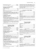
Round recesses can be assessed from Table 8-9. Their stretch values are based on the
ratio of the depth h to the length of the recess in flat L
s
.
8-9-2 Stretch Flange Forming
Stretch flanges, when viewed from the top, form a concave curvature. These are flanges
which on forming must be lengthened or stretched (Fig. 8-49). They may be compared to
flanges surrounding a hole in sheet metal. Processes such as extruding, dimpling, and coun-
tersinking are all basically stretch flange forming.
RDD
osin
=−
1
2
()
360 CHAPTER EIGHT
FIGURE 8-48 Dimensional values of a stretched recess.
TABLE 8-9 Stretch Values of Circular Recesses
Ratio L
s
/L
o
Ratio h/L
o
Stretch %
1.05 0.157 5
1.10 0.218 10
1.15 0.264 15
1.20 0.302 20
1.25 0.334 25
1.30 0.361 30
1.35 0.386 35
1.40 0.408 40
1.45 0.429 45
1.50 0.447 50
Suchy_CH08.qxd 11/08/05 10:57 AM Page 360
Downloaded from Digital Engineering Library @ McGraw-Hill (www.digitalengineeringlibrary.com)
Copyright © 2004 The McGraw-Hill Companies. All rights reserved.
Any use is subject to the Terms of Use as given at the website.
BENDING AND FORMING OPERATIONS
The evaluation of the flange type should be pursued by observing the flat layout of a
part, which clearly shows where the material for each flange may be taken from.
Owing to their stretching, the material thickness of stretch flanges decreases. This places
a lateral strain on the material, with a resulting circumferential tension. The strain S
e
can be
calculated from the ratio of the wall thickness ∆t and the amount of wall thickness change t
as follows:
(8-17)
A minus sign attached to Eq. (8-17) depicts the variation in wall thickness, which in stretch
flanges diminishes (−) and in shrink flanges increases (+).
From this relationship, other values may be assessed with the use of the formula
(8-18)
where all values are as shown in Fig. 8-50.
However, with the bend radius being too small, the value a of flange movement may be
approximated. In such a case, the material thickness is to be considered zero and the flange
width constant. The formula to be used is then
a = b(1− cosa) (8-19)
Stretch flanges are limited by the amount of material from which they can draw for their
development. Beyond such a limit, the flanges will crack around the edges and tear. Too
small a radius of curvature also adds to the problems, and it should be made as generous as
possible, with a definite preference for straight forming lines.
The limits on the 90° flange are as given by the equation
(8-20)
e
Rb
B
limit
=−
−
1
1
cos
/
α
e
a
Rb
B
=
−
∆t
t
e
=−
2
BENDING AND FORMING OPERATIONS 361
FIGURE 8-49 Stretch flange.
Suchy_CH08.qxd 11/08/05 10:57 AM Page 361
Downloaded from Digital Engineering Library @ McGraw-Hill (www.digitalengineeringlibrary.com)
Copyright © 2004 The McGraw-Hill Companies. All rights reserved.
Any use is subject to the Terms of Use as given at the website.
BENDING AND FORMING OPERATIONS
8-9-3 Shrink Flange Forming
Shrink flanges are those which are reduced in length on forming, or shrunk. The shrunk flange,
when viewed from the top, usually forms a convex line. The wall thickness of these flanges
increases, which is caused by a circumferential compression during the forming process.
The lateral strain, acting within the flange material, can be calculated by using Eq. (8-17).
Similarly as with the stretch flanges, other pertinent values may be assessed:
(8-21)
where the values are as shown in Figs. 8-50 and 8-51.
e
a
Rb
B
=−
+
362 CHAPTER EIGHT
FIGURE 8-50 Stretch flange geometry.
FIGURE 8-51 Shrink flange and its geometry.
Suchy_CH08.qxd 11/08/05 10:57 AM Page 362
Downloaded from Digital Engineering Library @ McGraw-Hill (www.digitalengineeringlibrary.com)
Copyright © 2004 The McGraw-Hill Companies. All rights reserved.
Any use is subject to the Terms of Use as given at the website.
BENDING AND FORMING OPERATIONS
And again, the value a of flange movement may be approximated, using Eq. (8-19).
Shrink flanges are actually quite difficult to form from a flat blank. The material is often
reluctant to succumb to such compressive stresses and has a tendency to wrinkle or buckle.
With wider flanges, the tendency to wrinkling is increased.
Buckling is found controllable where the ratio of the flange width to the material thick-
ness remains within a range of 3 to 4.
8-10 BENDING AND FORMING
PRESSURE CALCULATIONS
Several formulas are utilized for calculation of bending and forming pressures. They may
vary with the type of bending utilized.
1. Bending in a V-die, with rectangular cross-section:
(8-22)
where k
V
= die opening factor, 0.75 to 2.5 (larger values are for smaller R/t ratios and vice
versa). A 1.33 value is used for a die opening of 8 times metal thickness.
W = width of the bent-up portion
L = distance between material supports (see Fig. 8-52)
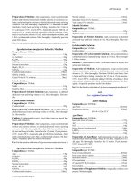
S = ultimate tensile strength (Table 8-10)
2. Bending in a U-die, equipped with a spring-loaded pressure pad:
(8-23)
where k
U
= die opening factor, 0.4 to 10
R
E
= radius, die edge (see Fig. 8-53)
R
D
= radius, bottom of U channel
P
pad
= pressure of spring-loaded support
P
k SWt
RRt
P
U
U
ED
=
++
+
2
pad
P
k SWt
L
V
V
=
2
BENDING AND FORMING OPERATIONS 363
TABLE 8-10 Ultimate Tensile Strength of Materials
Tons/In.
2
MPa [N/mm
2
]
Steel, low carbon, 1025 30–51.5 410–710
Steel, medium carbon, 1045 40–91 550–1,250
Steel, high carbon, 1095 45–106.5 620–1,470
Steel, stainless, 303 42.5–62.5 585–860
Aluminum alloy, cold worked 6.0–31.5 80–435
Aluminum alloy, heat treated 11.0–41.5 150–570
Copper 16–28.5 220–390
Phosphor bronze 20–64 275–880
Zinc 9.75–15.5 135–215
Suchy_CH08.qxd 11/08/05 10:57 AM Page 363
Downloaded from Digital Engineering Library @ McGraw-Hill (www.digitalengineeringlibrary.com)
Copyright © 2004 The McGraw-Hill Companies. All rights reserved.
Any use is subject to the Terms of Use as given at the website.
BENDING AND FORMING OPERATIONS
FIGURE 8-53 U-die bending geometry.
FIGURE 8-52 V-die bending geometry.
3. Bending with bottoming (coining):
P
bottom
= (2 to 4)P = Ap (8-24)
where P = bending pressure of the particular process
A = area of part, subjected to coining
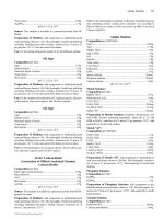
p = bending pressure (see Table 8-11)
364 CHAPTER EIGHT
Suchy_CH08.qxd 11/08/05 10:57 AM Page 364
Downloaded from Digital Engineering Library @ McGraw-Hill (www.digitalengineeringlibrary.com)
Copyright © 2004 The McGraw-Hill Companies. All rights reserved.
Any use is subject to the Terms of Use as given at the website.
BENDING AND FORMING OPERATIONS
FIGURE 8-54 Wipe bending geometry.
TABLE 8-11 Approximate Bending Pressures
Tons/in.
2
kPa
Material thickness, in. Material thickness, mm
Under 0.125 0.125–0.375 Under 3 3–10
Steel, annealed 29–36 36–43 0.4–0.5 0.5–0.6
Steel, hard 36–43 43–58 0.5–0.6 0.6–0.8
Aluminum 7–15 15–22 0.1–0.2 0.2–0.3
Brass 22–36 36–43 0.3–0.4 0.4–0.5
Source: Svatopluk
ˇ
Cernoch, Strojn
ˇ
e technická p
ˇ
ríru
ˇ
cka, 1977. Reprinted with permission from SNTL
Publishers, Prague, CZ.
4. Wipe bending dies’ pressure calculation:
(8-25)
where L = distance between supports of the material (see Fig. 8-54)
W = width of the bent-up portion
S = ultimate tensile strength (Table 8-10)
Subsequently, each of the three forces acting upon the appropriate point in the assembly is
one-third of the total force. These forces are: (1) force of blank holder; (2) bending force of
the punch; (3) final bottoming force of the punch (see Fig. 8-54).
(8-26)
P
SWt
L
1
2
0 333
or 2 or 3
= .
P
SWt
L
total-wipe
=
2
BENDING AND FORMING OPERATIONS 365
Suchy_CH08.qxd 11/08/05 10:57 AM Page 365
Downloaded from Digital Engineering Library @ McGraw-Hill (www.digitalengineeringlibrary.com)
Copyright © 2004 The McGraw-Hill Companies. All rights reserved.
Any use is subject to the Terms of Use as given at the website.
BENDING AND FORMING OPERATIONS
5. Calculation of the pressure involved in rotary bending is as follows:
(8-27)
where S
T
= Tensile strength of the formed material
L = PR + PT + B
all other values per Fig. 8-55.
PS
PL PT
L
total
= 225
2
.
()()
T
366 CHAPTER EIGHT
FIGURE 8-55 Rotary bending geometry.
(Reprinted with permission from Ready
Technology, Inc., Dayton, OH. Patent Number
5,404,742.)
Suchy_CH08.qxd 11/08/05 10:57 AM Page 366
Downloaded from Digital Engineering Library @ McGraw-Hill (www.digitalengineeringlibrary.com)
Copyright © 2004 The McGraw-Hill Companies. All rights reserved.
Any use is subject to the Terms of Use as given at the website.
BENDING AND FORMING OPERATIONS
DRAWN PARTS
9-1 DRAWING OF SHEET METAL
Drawing is a technological process during which a flat piece of sheet-metal material (i.e.,
blank) is transformed into a hollow, three-dimensional object. Such transformation can be
produced either in a single step, or in a sequence of operations, each of them changing the
shape but partially.
During the process of drawing, the material is forced to follow the movement of a
punch, which pulls it along, on its way through the die. There the shape of the part and
sometimes even the thickness of it are altered.
At first, the drawn material has to overcome its own elastic limit, succumbing to plastic
deformation right afterwards. Various forces are acting upon the drawn cup (as shown in
Fig. 9-1), be it the blankholder’s pressure, or the friction between the drawn shell and other
components of tooling. The blank is sometimes restricted from unreservedly following the
punch, by having its edges confined between the surface of the die and those of a
blankholder.
The main area of concern on the drawn part is located between the heel of the verti-
cal wall and the bottom of the shell, where, due to the change in flow direction, the ver-
tical tension acting upon the material is transformed into a triple-axial tension. In this
section, the material is being bent, while moving around the edge of the drawing punch,
only to be straightened right afterwards, so that another successive segment can be bent-
and-straightened. This is where the wall thickness can often become diminished on
account of the length of the shell, which is being increased by the drawing process.
Because of such drastic changes within material, this is where much cracking and tear-
ing can be observed.
In drawing, the metal taken from the flange of the shell is used up to produce increase
in height of the part. A rather crude demonstration of this shift is depicted in Fig. 9-2. Here
the segments of material are being displaced, flowing away from the flange toward the
body of the shell, pulled by the action of the drawing punch and drawing die.
The basic shape in drawing operation, the “blank,” is but a flat piece of sheet-metal
material of uniform thickness, most often round. From this shape, a shell can be drawn.
Even though during the process of drawing the blank’s shape changes, often along with its
thickness, its volumnar value remains the same, should it be drawn into a short, thick-
walled cylinder, or a tall, thin-walled shell (Fig. 9-3).
With regard to the thinning of the drawn shells’ wall, the final products can be divided
into two basic categories:
• Those having the wall of the same thickness as the blank (Fig. 9-4a)
• Those having the wall thickness diminished (Fig. 9-4b)
CHAPTER 9
367
Suchy_CH09.qxd 11/08/05 11:08 AM Page 367
Downloaded from Digital Engineering Library @ McGraw-Hill (www.digitalengineeringlibrary.com)
Copyright © 2004 The McGraw-Hill Companies. All rights reserved.
Any use is subject to the Terms of Use as given at the website.
Source: HANDBOOK OF DIE DESIGN
368 CHAPTER NINE
FIGURE 9-1 Forces involved in cup-drawing process.
FIGURE 9-2 Displacement of metal in drawing.
Suchy_CH09.qxd 11/08/05 11:08 AM Page 368
Downloaded from Digital Engineering Library @ McGraw-Hill (www.digitalengineeringlibrary.com)
Copyright © 2004 The McGraw-Hill Companies. All rights reserved.
Any use is subject to the Terms of Use as given at the website.
DRAWN PARTS
The size of the blank must be well assessed, to provide for all the needed amount of
material and yet not be excessive in size or volume. Drawing from blanks the diameter of
which is too small for their depth always poses a problem, as the thinning of the walls may
be unreasonable and products may emerge from the die distorted or fractured.
Numerous other influences controlling the outcome of the drawing process can be found
within mechanical properties of the material, such as strength, ductility, elasticity, and even
thickness of the drawn stock. Should these values be either inadequate or excessive, they
certainly will have an effect on the drawn part, and either favorably or negatively alter the
whole process and its outcome.
The total expansion in depth often cannot be attained in a single operation. No material,
with the exception of a rubber band, has such elastic properties as to allow for its stretch-
ing into depths greater than certain limiting percentages, which are listed later in this chap-
ter. If a part is drawn more than it can tolerate, its stretching will place such a strain on its
structure that a permanent deformation followed by fractures and tearing will result.
Therefore, drawing into greater depths must be done in stages, with each operation to
be performed within the limits set for that particular material. And each drawing pass
should stretch the shell slightly more until a final drawn cup is produced (Fig. 9-5).
DRAWN PARTS 369
FIGURE 9-3 Volumnar equality of shells made from the same blank.
FIGURE 9-4 Two types of drawing operations.
Suchy_CH09.qxd 11/08/05 11:08 AM Page 369
Downloaded from Digital Engineering Library @ McGraw-Hill (www.digitalengineeringlibrary.com)
Copyright © 2004 The McGraw-Hill Companies. All rights reserved.
Any use is subject to the Terms of Use as given at the website.
DRAWN PARTS
To produce a well-shaped and high-quality drawn part, the edges of both punch and die
must be radiused, or chamfered; otherwise tearing of material will occur. The radii should
be quite liberal, ranging at least four times the material thickness, even though the part’s
blueprint does not call for them. Where a drawn product must have smaller than possible
radii, these should be produced later, in the restriking operation.
The restriking process does not draw the shape any further; rather, it forces the already
drawn product to conform dimensionally to the requirements, unacquirable otherwise.
During restrike, radii may be produced smaller than those enforced by the requirements of
the drawing process. Bottoms may be flattened (somewhat), or bulged, or sides of a shell
may be straightened (Fig. 9-6).
Restriking differs from redrawing in that the punch does not attempt to extend the drawn
shell, whereas redrawing is used strictly for deepening of the drawn portion.
370 CHAPTER NINE
FIGURE 9-5 Sequence of drawing operations.
FIGURE 9-6 Restriking operation.
Suchy_CH09.qxd 11/08/05 11:08 AM Page 370
Downloaded from Digital Engineering Library @ McGraw-Hill (www.digitalengineeringlibrary.com)
Copyright © 2004 The McGraw-Hill Companies. All rights reserved.
Any use is subject to the Terms of Use as given at the website.
DRAWN PARTS
Repeated redrawing will produce strain hardening within the drawn material. After two
or three drawing passes, some materials are hardened so greatly that the press force to over-
come such an obstacle will have to be tremendous, and yet it may not achieve another
extension in shape, as the hardened part may tear or rupture.
In such cases annealing of the drawn material must be performed in between. Annealing
brings the mechanical properties of metal back to its predrawing stage, or at least quite close
to it. Additional drawing passes may then be performed without causing unnecessary dis-
turbances of the part’s structure.
Some materials, such as brass, copper, and some steel, have to be annealed between every
drawing stage. The effect of their strain hardening is too massive, handicapping further
drawing operations. This may be observed with a piece of soft copper wire, which, when
bent up and down several times in succession, suffers from such strain hardening that it
becomes quite rigid.
Aluminum wire, on the other hand, softens and tears readily, with the breakage occur-
ring within the area of the bend. When drawn, aluminum can attain deeper shapes in fewer
drawing passes and with less annealing in between. Naturally, not all aluminum grades per-
form equally, which makes the above statement applicable mainly to alloys designated for
drawing purposes.
Drawing differs from other metalworking processes in that it totally exploits the elastic
and plastic properties of materials. The flat blank, forced to alter its shape to comply with
the tooling, wraps around the punch, tightly adhering to its surface. Drawn parts always
conform to the shape of the punch, while the opening in the die is immaterial, as long as its
size is adequate for the given stock thickness (Fig. 9-7).
9-2 METAL MOVEMENT IN DRAWING
OPERATION
During the process of sheet-metal drawing, the metal of the blank is exposed to various
influences, which lead to its alteration in shape and sometimes in thickness (see Fig. 9-1).
A plastic deformation of the material can be seen in the area, exposed to the pressure of the
DRAWN PARTS 371
FIGURE 9-7 Drawn material conforms to the shape of the punch.
Suchy_CH09.qxd 11/08/05 11:08 AM Page 371
Downloaded from Digital Engineering Library @ McGraw-Hill (www.digitalengineeringlibrary.com)
Copyright © 2004 The McGraw-Hill Companies. All rights reserved.
Any use is subject to the Terms of Use as given at the website.
DRAWN PARTS
blankholder, while the plastic deformation caused by the drawing punch face is minimal.
The plastic deformation occurring within the flange is positive where the radial tension is
concerned, and negative owing to compression in the tangential direction. The direction of
deformation normal to the flange is at first negative, with the resulting thinning of walls.
But at the diametral distance greater than
Punch dia. + 1.214R
the deformation becomes positive, with subsequent increase in thickness (Fig. 9-8).
Plastic deformation of the material may be enhanced or decreased by altering the
amount of friction between the drawn part and its tooling. However, the influence of fric-
tion varies with its location within the drawing process. Friction between the material and
the drawing die or blankholder causes the radial tension and the ultimate coefficient of cup-
ping to increase, with subsequent restriction of the maximum possible depth of draw.
Friction between the material and drawing punch exerts an opposite influence on the out-
come by increasing the maximum possible depth of the draw as a consequence of increase
in friction.
This scenario may sometimes be enhanced by frictional inserts in the punch or by
roughing of its cylindrical surface. The alteration is efficient even as a prevention of the
excessive plastic deformation, or occurrence of wrinkles.
Wrinkling of material can also be prevented by the inclusion of a blankholder
within the drawing die arrangement. The blankholder not only prevents wrinkling of
the flange, it also retains the blank, so that it may not be pulled into the die without
being drawn.
Not all materials need the blankholder, though. Some thicker stock may be successfully
drawn without being retained under pressure. However, deforming influences within the
flange may develop, caused by the tension s, the value of which depends on the cupping
strain factor E
c
. Where such tension is greater than the critical tension s
crit
, which is depen-
dent on the thickness of stock, a blankholder is necessary.
A cross-section of the drawn part is shown in Fig. 9-9. Here the thinning of various areas
around the punch tip is exaggerated for clarity. The uneven upper surface is caused by dif-
ferences in anisotropy of the material, which is explained in the next section.
372 CHAPTER NINE
FIGURE 9-8 Structural changes during drawing operation.
Suchy_CH09.qxd 11/08/05 11:08 AM Page 372
Downloaded from Digital Engineering Library @ McGraw-Hill (www.digitalengineeringlibrary.com)
Copyright © 2004 The McGraw-Hill Companies. All rights reserved.
Any use is subject to the Terms of Use as given at the website.
DRAWN PARTS
9-3 TECHNOLOGICAL ASPECTS OF
DRAWING PROCESS
A drawn part is exposed to various technological influences, which affect every manufac-
turing process and its outcome. These are factors, including but not limited to the type of
tooling, the type of manufacturing process, the amount of friction, speed of the process,
temperature of the product and its tooling, and numerous other influences, exerting their
control over the final product.
All these factors may affect the part and its manufacturing process either singularly or
in a combination of two or more circumstances. For example, the drawing process itself
will be affected by the amount of friction, which may give rise to the temperature of work-
ing surfaces, with subsequent wear of the tooling.
There are numerous small and large influences, all insidiously waiting to be omitted
from the total assessment of the situation, so that they may manipulate the process unex-
pectedly and at the most inopportune moment. All these aspects have to be properly eval-
uated so that their span of control is limited in scope and in magnitude as well.
9-3-1 Suitability of Materials for Drawing
A valuable contribution to the successful drawing process is a properly selected drawing
material. The choice is governed mainly by the material’s drawability, or rather by the por-
tion of it regarding the deformation and its distribution. The value of deformation should
be within 25 to 75 percent of the value of drawability.
Drawability of metals can be defined as their capacity to assume the predetermined
shape without suffering any loss of stability, without fracturing or being otherwise distorted
by the drawing process.
DRAWN PARTS 373
FIGURE 9-9 Cross section of the drawn shell. (From: Practical Aids
For Experienced Die Engineer, Die Designer, and Die Maker 1980.
Reprinted with permission from Arntech Publishers, Jeffersontown, KY.)
Suchy_CH09.qxd 11/08/05 11:08 AM Page 373
Downloaded from Digital Engineering Library @ McGraw-Hill (www.digitalengineeringlibrary.com)
Copyright © 2004 The McGraw-Hill Companies. All rights reserved.
Any use is subject to the Terms of Use as given at the website.
DRAWN PARTS
9-3-1-1 Drawability Theories and Testing. There are several theories on materials’
drawability, all supported by a thorough testing. Erichsen’s test was carried in accordance
with PN/68/11-04400 (Polish Standard), where a punch ending with a ø20-mm ball was
used. The resulting fracture occurrence was determined with 0.01-mm accuracy. Jovignot’s
test utilized a ø50-mm die with ø5-mm profile radius. The accuracy of these findings was
also 0.01 mm. In the Swift test, a ø32-mm punch with a flat face was used. The Engelhardt-
Gross test employed a ø20-mm punch against the ø52-mm blank. The Fukui test, using a
conical cup, was performed with ø8- to 27-mm punches. Siebel-Pomp tested 80 × 80 mm
samples with a central opening of ø12 mm.
Various testing methods established the drawability factor as a function of the mechan-
ical makeup of the material, depending mainly on its strength, elastic/plastic properties, and
chemical composition.
A certain lack of relationship between Erichsen’s drawability index and the chemical
composition of the material renders the influence of the latter meaningless. Tested materi-
als ranged in the following values: 0.045 to 0.16 percent carbon, 0.24 to 0.48 percent man-
ganese, 0.011 to 0.039 percent phosphorus, 0.005 to 0.03 percent sulfur.
Other findings proved the influence of phosphorus and manganese on drawability con-
troversial. In these tests, the phosphorus content ranged between 0.01 and 0.025 percent,
while manganese was included at 0.25 to 0.39 percent.
Still other tests found that the 0.015 to 0.025 percent of phosphorus was actually an
improvement to drawability.
The most pronounced effect on the materials’ drawability was considered normal
anisotropic plasticity, where the actual tests fully confirmed previously obtained theoreti-
cal analyses. However, the lack of conformity between the theory and experiments in the
case of strain-hardening influence on the drawability was too obvious.
Experimental findings also substantiated the difference in the drawability of materials
of the same thickness, as based on the type of manufacturing process of the basic steel
sample. Materials stabilized by aluminum were found to have their elastic limits approx-
imately 5 percent greater than those stabilized by titanium, whereas the drawability of tita-
nium-stabilized steel was found 7 percent greater than that of the aluminum-stabilized steel.
9-3-1-2 Normal Anisotropy. Suitability of drawing materials should also be evaluated
on the basis of its coefficient of normal anisotropy r. This coefficient is a ratio of the actual
deformation (or variation) within the metal to the variation in its thickness. The relationship
can be defined as
(9-1)
where all values are as shown in Fig. 9-10.
Coefficient of normal anisotropy is a speculative value, comparing the behavior of the
flange material with that in the drawn section and with that located under the face of the draw-
ing punch. A proper development of tangential and radial deformations within the flange and
an attainment of low amounts of deformation within the drawn section of the shell are vital to
the success of the drawing process. With higher values of coefficient of normal anisotropy,
the material’s formability will be greater, producing deeper draws and lowering the cupping
strain factor.
Since the coefficient of normal anisotropy r is grain orientation-dependent, its value is
specified with respect to its variation from the grain line, which is considered at 0°.
Subsequently, r
0
goes along the grain line, r
45
at 45°, and r
90
at 90° (see Fig. 9-11). The
mean value of the normal coefficient of anisotropy can be obtained from the formula
(9-2)
r
rrr
=
++
0
45
90
2
4
r
bb
tt
=
ln
ln
(/)
(/)
0
0
374 CHAPTER NINE
Suchy_CH09.qxd 11/08/05 11:08 AM Page 374
Downloaded from Digital Engineering Library @ McGraw-Hill (www.digitalengineeringlibrary.com)
Copyright © 2004 The McGraw-Hill Companies. All rights reserved.
Any use is subject to the Terms of Use as given at the website.
DRAWN PARTS
while the surficial anisotropy can be obtained with the formula
(9-3)
The value of ∆r influences the variation in drawing results with respect to the grain line
of the material, which present themselves as a variation in straightness of the upper edge of
the drawn shell, as shown in Fig. 9-12.
Where the anisotropy r would be greater in the direction of 0° and 90°, in that direction
the material will be drawn to greater depths than along the 45° line, bringing the value of
∆r for 0° and 90° above zero.
Where the anisotropy at 45° exceeds the other directionally oriented values, the inequal-
ity in the surface will be the most pronounced along that line, and the value of ∆r will be
driven under zero.
∆r
rrr
=
−+
0
45
90
2
2
DRAWN PARTS 375
FIGURE 9-10 Values in normal anisotropy.
FIGURE 9-11 Anisotropy in a plane (surficial).
Suchy_CH09.qxd 11/08/05 11:08 AM Page 375
Downloaded from Digital Engineering Library @ McGraw-Hill (www.digitalengineeringlibrary.com)
Copyright © 2004 The McGraw-Hill Companies. All rights reserved.
Any use is subject to the Terms of Use as given at the website.
DRAWN PARTS
9-3-2 Severity of Draw and Number of Drawing Passes
The severity of the drawing operation may be expressed by the relationship of the blank
diameter to the cup diameter. This ratio, often called a cupping ratio, allows for an assess-
ment of the amount of drawing passes needed to produce a particular shell.
Where this ratio is exceeded, a fracture of the shell results, attributable to the exhaustion
of drawing properties of the particular material. This means that from a blank of a certain
size, only a certain cup diameter and its depth may be produced during a single drawing pass.
The severity of draw is calculated using Eq. (9-4):
(9-4)
where K is the severity of draw factor and M is the reverse value of severity of draw factor.
Recommended values of M to be used for the first drawing pass are M = 0.48 to 0.60,
with dependence on the drawn material properties.
The CSN 22 7301 (Czech National Standard, similar to DIN) recommends a range
from
(9-5a)
up to
(9-5b)
The advantage of using the severity of draw calculations at the early stages of the drawn
shell evaluation is the immediate assessment of the number of drawing passes needed.
Subsequent drawing passes may use the CSN 22 7301 recommendations of the M-value
range, starting at
(9-6a)
M
d
n
n
−
−
=
+
min
.70 0 01
100
1
M
D
max
.
=
+60 0 01
100
0
M
D
min
.
=
+50 0 01
100
0
K
D
d
M
d
D
==
0
0
or
376 CHAPTER NINE
FIGURE 9-12 Uneven edges of drawn shells due to surficial anisotropy ∆r.
Suchy_CH09.qxd 11/08/05 11:08 AM Page 376
Downloaded from Digital Engineering Library @ McGraw-Hill (www.digitalengineeringlibrary.com)
Copyright © 2004 The McGraw-Hill Companies. All rights reserved.
Any use is subject to the Terms of Use as given at the website.
DRAWN PARTS
and up to
(9-6b)
The total of all M coefficients for the particular drawing sequence is dictated by the
geometry of all drawn and redrawn shapes and by the subsequent geometry of the finished
shell. It may be calculated by using Eq. (9-7a):
(9-7a)
and subsequently
(9-7b)
With a greater radius of the drawing die ranging between 8t and 15t, smaller values of
the severity of the draw coefficient may be used. Subsequently, with smaller drawing die
radii such as those ranging between 4t and 8t, larger coefficients are recommended.
For metals low in ductility, such as brass and some harder grades of aluminum, the
coefficient should be made purposely larger and lowered for more ductile materials.
The height h of each step of drawing sequence (see Fig. 9-13) for various types of mate-
rials must be figured out, and perhaps even tested considering the material’s properties.
M
d
D
d
d
d
d
d
d
d
D
n
n
n
total
= ×××× =
−
1
0
2
1
3
21
MMMM M
ntotal
=××××
123
M
d
n
n
−
−
=
+
max
.80 0 01
100
1
DRAWN PARTS 377
FIGURE 9-13 Drawing sequence. Reprinted with permission from Zdeneˇk Machácˇek and
Karel Novotn´y, Speciální Technologie I., published by C
ˇ
VUT, Brno, Czech Republic.
Suchy_CH09.qxd 11/08/05 11:08 AM Page 377
Downloaded from Digital Engineering Library @ McGraw-Hill (www.digitalengineeringlibrary.com)
Copyright © 2004 The McGraw-Hill Companies. All rights reserved.
Any use is subject to the Terms of Use as given at the website.
DRAWN PARTS
Other guidelines are provided by the final part’s dimensioning demands and restrictions.
As already mentioned, sometimes annealing between the steps becomes necessary.
9-3-3 Cupping Strain Factor E
c
The strain factor of the cupping operation shows the actual strain in the metal created by its
elongation during the deep-drawing process. For evaluation of this type of stress, Eq. (9-8a)
should be utilized, perhaps in replacement of the severity of draw calculations included in
the preceding section.
(9-8a)
Subsequently, to calculate the mean diameter of the cup d with respect to the allowable
amount of the cupping strain factor, this formula can be written as
(9-8b)
The cupping strain factor, depicting the strain effect of cupping after the n-redrawing
operation, is
(9-9)
and the ultimate strain factor will be
(9-10)
where e is the maximum elongation at fracture, percent.
Several recommended cupping ratios and their respective strain factors are shown
in Table 9-1.
E
e
max
=+1
100
E
h
H
tD d
dt
cn
n
n
n
nn
,
==
+()
2
d
D
E
c
=
−21
E
h
H
Dd
dD d
D
d
c
==
−
−
=
+
2
4
1
2
22
()
()
378 CHAPTER NINE
TABLE 9-1 Recommended Maximum Reductions for Cupping
Reduction in Cupping Strain factor, Reduction in
Metal diam., % (max)
∗
ratio, D/dE
c,n
area, % (max)
†
Aluminum alloys 45 1.80 1.40 28
Aluminum, heat-treatable 40 1.60 1.30 23
Copper, tombac 45 1.80 1.40 28
Brasses, high, 70/30, 63/37 50 2.00 1.50 33
Bronze, tin 50 2.00 1.50 33
Steel, low-carbon 45 1.80 1.40 28
Steel, austenitic stainless 50 2.00 1.50 33
Zinc 40 1.60 1.30 23
∗
= 100(1 − d/D).
†
= 100(1 − a/A)
Source: Frank W. Wilson, Die Design Handbook, New York, 1965. Reprinted with permission from the
McGraw-Hill Companies.
Suchy_CH09.qxd 11/08/05 11:08 AM Page 378
Downloaded from Digital Engineering Library @ McGraw-Hill (www.digitalengineeringlibrary.com)
Copyright © 2004 The McGraw-Hill Companies. All rights reserved.
Any use is subject to the Terms of Use as given at the website.
DRAWN PARTS
As each redrawing stage becomes progressively more impaired by the strain-hardening
influence, the strain factor for each successive redrawing operation should always be
smaller than the preceding one. Usually the first redrawing strain factor may be derived
from the original E
c
value by calculating
with the exponent x to be between 0.4 and 0.6. Usually a strain factor of 1.12 to 1.18 may
be utilized in redrawing most materials.
In multioperational redrawing sequences, the total strain factor should be considered to
be a multiple of the respective stress factors of all drawing operations.
This relationship may be expressed as
(9-11)
This means that should a total stress factor be E
c
= 1.4, stress factors of various
redrawing operations within the operational sequence should be chosen to equal their
total multiple to 1.4.
The amount of stress factor value is mainly influenced by the ductility and strain hard-
ening of the particular material. Where the total stress factor amount is reached sooner than
the finished product is produced, annealing of the shell must be performed.
Singular strain factors—as may be seen from the formulas above—depend on ratios of
the blank diameter to the shell diameter, or on the height of the drawn cup. The thickness
of metal and the amount of friction within the particular drawing pass are also of impor-
tance in this process.
9-3-4 Reduction Ratios
A shell may be drawn into a certain depth only without a damage being caused to its shape
or structure. Where greater depths or reductions are required, subsequent drawing passes
must be added. To determine the amount of reduction per given shell size, the following
formulas should be used.
For the first operation die:
(9-12a)
For all redrawing dies:
(9-12b)
(9-12c)
where D= blank diameter
d
1
= mean diameter of first shell
d
2
= mean diameter of second shell
d
3
= mean diameter of third shell
B
1
and B
2
= factors depending upon thickness of metal to be drawn, from Table 9-2
d
Bd
d
3
22
2
100 0 635
=
×
− .
d
Bd
d
2
21
1
100 0 635
=
×
− .
d
BD
D
1
1
100 0 635
=
×
− .
EEEE E
cn−
=××××
total
123
EE
c
x
redraw
= ()
DRAWN PARTS 379
Suchy_CH09.qxd 11/08/05 11:08 AM Page 379
Downloaded from Digital Engineering Library @ McGraw-Hill (www.digitalengineeringlibrary.com)
Copyright © 2004 The McGraw-Hill Companies. All rights reserved.
Any use is subject to the Terms of Use as given at the website.
DRAWN PARTS
The reduction ratio R
c
may be calculated by using the following formula:
(9-13)
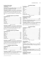
A graphical demonstration of the strain factor and blank dimension relationship for
single- and double-action dies can be observed in Fig. 9-14. For visual representation of
drawing sequence and terminology applicable to the above formulas, refer to Fig. 9-15. A
rough assessment of the blank reduction in drawing can be ascertained by using the graph
provided in Fig. 9-16.
R
Dd
D
c
=
−100( )
380 CHAPTER NINE
TABLE 9-2 Factors B
1
and B
2
Stock thickness
First-operation die, Any redrawing die,
in. mm B
1
value B
2
value
0.015–0.018 0.38–0.46 61 74
0.021 0.53 58 73
0.022–0.024 0.56–0.61 56 72
0.027 0.69 54 71
0.031 0.79 50 70–71
0.062–0.109 1.57–2.77 47 70
0.125–0.250 3.18–6.35 51 65
400
250
160
100
63
40
25
Ratio D/t of blank diam. to thickness
0.25
0.40
0.63
1.0
1.6
2.5
4.0
100 t/D
1.4 1.5 1.6 1.7 1.8 1.9 2.0
Strain factor, E
E
c
E
c
·E
1
E
c
·E
1
·E
2
E
c
E
c
·E
1
E
c
·E
1
·E
2
Double–action
Single–action
FIGURE 9-14 Relationship between strain factors and blank dimensions for deep
drawing with single- and double-action dies. (From: Frank W. Wilson, Die Design
Handbook, New York, 1965. Reprinted with permission from The McGraw-Hill
Companies.)
Suchy_CH09.qxd 11/08/05 11:08 AM Page 380
Downloaded from Digital Engineering Library @ McGraw-Hill (www.digitalengineeringlibrary.com)
Copyright © 2004 The McGraw-Hill Companies. All rights reserved.
Any use is subject to the Terms of Use as given at the website.
DRAWN PARTS
9-3-4-1 Maximum percentage of reduction. A maximum percentage of reduction for
deep-drawing materials of various thicknesses is slightly higher than the values included
previously. Intermediate annealing is to be utilized only when the shells become strain
hardened or when cracks begin to form.
Table 9-3, giving the values of the maximum possible reduction, should be used for dies
operating in hydraulic presses, where the pressure of the blankholder is constant. The per-
centages given here are recommended for drawing operations only where no ironing is
involved. Should ironing of the shell be needed, the values shown in Table 9-3 must be
reduced.
DRAWN PARTS 381
FIGURE 9-15 Drawing sequence.
TABLE 9-3 Maximum Percentage of Reduction for Deep-Drawing Materials
Stock thickness
First-drawing Second-drawing Any additional
in. mm operation operation drawing operation
0.010 0.25 27 18 17
0.015 0.38 32 20 19
0.021 0.53 35 21 20
0.024 0.61 39 22 21
0.031 0.79 42 23 22
0.036 0.91 44 26 24
0.042 1.07 46 28 25
0.046 1.17 47 28 25
0.054 1.37 47 29 26
0.062–0.124 1.57–3.15 48 30 27
0.125–0.250 3.18–6.35 47 28 26
Suchy_CH09.qxd 11/08/05 11:08 AM Page 381
Downloaded from Digital Engineering Library @ McGraw-Hill (www.digitalengineeringlibrary.com)
Copyright © 2004 The McGraw-Hill Companies. All rights reserved.
Any use is subject to the Terms of Use as given at the website.
DRAWN PARTS
9-3-4-2 Drawing of Stainless-Steel Shells. Drawing of stainless-steel shells may basi-
cally follow the same procedures as drawing of other materials. But a slight change in
reduction formulas is necessary, for in the drawing process, stainless steel behaves differ-
ently from other materials.
For example, a large reduction from the basic flat blank is possible for stainless steel of
18-8 type, but the subsequent drawing operations must be very moderate.
A chromium type 17-20 steel cannot be drawn into great depths from a blank, yet larger
reductions may be obtained through succeeding redrawing operations.
Generally, chromium-nickel stainless steel strain hardens quite readily, for which rea-
son more frequent anneals, combined with lower drawing speeds and better lubrication, are
required.
The amount of reduction of the particular stainless-steel material may be calculated with
the help of constants B
SS-1
and B
SS-2
, listed in Table 9-4.
382 CHAPTER NINE
FIGURE 9-16 Graphical method of blank reduction in drawing.
TABLE 9-4 Factors B
ss-1
and B
ss-2
First-operation die, Any redrawing die,
Material thickness B
ss-1
value B
ss-2
value
in. mm 18-8 SS 17Cr SS 18-8 SS 17Cr SS
0.015–0.018 0.38–0.46 61 68 81 77.5
0.021 0.53 58 65 80 76.5
0.022–0.024 0.56–0.61 56 63 80 75.5
0.027 0.69 54 60 79 74.5
0.031 0.79 50 56 77 74
0.062–0.109 1.57–2.77 47 53 75 73.5
0.125–0.250 3.18–6.35 51 51 65 65
Suchy_CH09.qxd 11/08/05 11:08 AM Page 382
Downloaded from Digital Engineering Library @ McGraw-Hill (www.digitalengineeringlibrary.com)
Copyright © 2004 The McGraw-Hill Companies. All rights reserved.
Any use is subject to the Terms of Use as given at the website.
DRAWN PARTS
Annealing between drawing stages is required for stainless. The preferred press equip-
ment to be used is a double-action press or a single-action die with a drawing collar and an
air cushion.
The formula for obtaining the maximum reduction in stainless-steel material to be used
for the first operation die is
(9-14a)
And for all succeeding redrawing dies:
(9-14b)
and
(9-14c)
where D = blank diameter
d
1
= mean diameter of first shell
d
2
= mean diameter of second shell
d
3
= mean diameter of third shell, and so on
B
SS-1
and B
SS-2
= constants, depending upon the thickness of metal to be drawn, from
Table 9-4
Stainless steel is an interesting material to work with, as it has its own mysteries and sur-
prises. Already the fact that some nonmagnetic stainless steel turns positively magnetic
after second or third drawing sequence, is worth pondering upon.
9-3-5 Strain Hardening of Material
The research has asserted that the strain-hardening coefficient has a dual effect on the for-
mation of wrinkles in drawn material. First, it enhances the material’s resistance to wrin-
kling through its supportive action toward the buckling modulus. Further, it affects the
distribution of strain, caused by the action of drawing, while supporting the development
of higher compressive stresses within the walls of shells.
To eliminate the effect of strain hardening, radial tension in the walls of the drawn part
must be enhanced, and the die radius should be decreased. Also the blankholder’s pressure
has to be increased, while lower-grade lubricants should be utilized.
Wrinkling of drawn parts usually begins quite close to the die radius; that’s where the com-
pressive stresses within the material are the largest. Where the pressure of the blankholder is
inadequate, these wrinkles will increase; but with higher blank-holding pressure, fracturing of
metal covering the tip of a punch will occur.
In cold-rolled steels and high-strength low-alloyed materials the limitation in drawing
depth due to fractures or wrinkling was already established. In high-strength low-alloyed
materials, the tendency to wrinkling is known as well, which—in order to be prevented—
will demand higher blank-holding pressures applied against the blank.
In martensitic stainless steel, the strain-hardening tendency of the material decreases as
the temperature rises. Yield stress can be lowered by the use of coarse-grained material,
provided its surface layer is not as coarse as so-called “orange-peel” texture. Coarsely
grained material also displays an increase in its ductility.
d
Bd
d
3
2
2
100 0 625
=
−
ss-2
and so on.
.
d
Bd
d
2
1
1
100 0 625
=
−
ss-2
.
d
BD
D
1
100 0 625
=
−
ss-1
.
DRAWN PARTS 383
Suchy_CH09.qxd 11/08/05 11:08 AM Page 383
Downloaded from Digital Engineering Library @ McGraw-Hill (www.digitalengineeringlibrary.com)
Copyright © 2004 The McGraw-Hill Companies. All rights reserved.
Any use is subject to the Terms of Use as given at the website.
DRAWN PARTS