Guide for Sound Insulation in Wood Frame Construction Part 8 ppt
Bạn đang xem bản rút gọn của tài liệu. Xem và tải ngay bản đầy đủ của tài liệu tại đây (579.68 KB, 11 trang )
Page 77 of 103
IRC RR-219: Guide for Sound Insulation in Wood Frame Construction March 2006
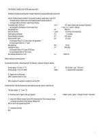
Load Bearing Double Stud Partition Wall
Users are urged to see the drawings of joint finishing details.
Floor topping Partition Wall/Floor Sidewall
No topping
(basic subfloor)
SFCASP2A.pdf
SFFIGB32.pdf
19 mm OSB
stapled to subfloor
SFCASP2B.pdf Same as above
Corresponding AutoCAD drawings (*.dwg) are given with the CD-ROM.
Return to Airborne Table Return to Impact Table
Page 78 of 103
IRC RR-219: Guide for Sound Insulation in Wood Frame Construction March 2006
Drawing SFCASP2A.pdf
Partition Wall
W1: Double 2x4 (38x89 mm) wood stud wall having studs spaced 16” (406 mm) o.c., with double sole plates. 1” (25 mm)
separation between the rows of studs.
W2: 3-1/2” (90 mm) Unfaced Thermal/Acoustic Batt Insulation filling the wall cavity.
W3: One layer of 5/8” (15.9 mm) SHEETROCK
®
BRAND FIRECODE C CORE gypsum panels attached vertically and
fastened with 2” (52 mm) or longer screws placed 16” (406 mm) o.c.
Topping
None
Floor
F1: 3/4” (19 mm) OSB floor decking fastened with 2” (51 mm) or longer #10 straight shank wood screws placed 6”
(150 mm) o.c. at edges and 12” (305 mm) o.c. in the field
F2: 2x10 (38x235 mm) wood joists spaced 16” (406 mm) o.c.
F3: 6” (150 mm) Unfaced Thermal/Acoustic Batt Insulation.
F4: Bridging and strapping; 1x3 (19x64 mm) strapping 24” (610 mm) o.c. used as furring strips, 1x3 (19x64 mm) bracing
no more than 72” (1800 mm) o.c. located at strapping points.
F5: Resilient channels spaced 16” (406 mm) o.c. The resilient channels installed perpendicular to the strapping using 1-
5/8” (42 mm) drywall screws.
F6: Two layers of 5/8” (15.9 mm) SHEETROCK
®
BRAND FIRECODE C CORE gypsum panels. The base layer attached
with 1-5/8” (42 mm) or longer screws placed 12” (305 mm) o.c. at the edges and 24” (610 mm) o.c. in the field. The
face layer attached with 2” (52 mm) or longer screws placed 12” (305 mm) o.c. at the edges and in the field. The
screws placed so as not to penetrate into the strapping or joists.
Floor/Partition-Wall Intersection
J1: Two 2x10 (38x235 mm) wood joists.
J2: 2x4 (38x89 mm) nailing plates attached to studs in floor cavity to support strapping.
Common Details
Corridor walls, Caulking details.
Page 79 of 103
IRC RR-219: Guide for Sound Insulation in Wood Frame Construction March 2006
Drawing SFCASP2B.pdf
Partition Wall
W1: Double 2x4 (38x89 mm) wood stud load-bearing wall having studs spaced 16” (406 mm) o.c., with double head
plates. 1” (25 mm) separation between the rows of studs.
W2: 3-1/2” (90 mm) Unfaced Thermal/Acoustic Batt Insulation filling the wall cavity.
W3: One layer of 5/8” (15.9 mm) SHEETROCK
®
BRAND FIRECODE C CORE gypsum panels attached attached vertically
and fastened with 2” (52 mm) or longer screws placed 16” (406 mm) o.c.
Topping
T1: 3/4” (19 mm) OSB overlay installed perpendicular to the subfloor with staggered joints fastened with staples not less
than 1/16” (1.6 mm) diameter, and 1/2” (12.5 mm) crown and 1-1/2” (38 mm) length spaced at 6” (150 mm) o.c. along
edge and 8” (203 mm) o.c. in the field.
Floor
F1: 3/4” (19 mm) OSB floor decking fastened with 2” (51 mm) or longer #10 straight shank wood screws placed 6”
(150 mm) o.c. at edges and 12” (305 mm) o.c. in the field.
F2: 2x10” (38x235 mm) wood joists spaced 16” (406 mm) o.c.
F3: 6” (150 mm) Unfaced Thermal/Acoustic Batt Insulation.
F4: Bridging and strapping; 1x3 (19x64 mm) strapping 24” (610 mm) o.c. used as furring strips, 1x3 (19x64 mm) bracing
no more than 72” (1800 mm) o.c. located at strapping points.
F5: Resilient channels spaced 16” (406 mm) o.c. The resilient channels installed perpendicular to the strapping using 1-
5/8” (42 mm) drywall screws.
F6: Two layers of 5/8” (15.9 mm) SHEETROCK
®
BRAND FIRECODE C CORE gypsum panels. The base layer attached
with 1-5/8” (42 mm) or longer screws placed 12” (305 mm) o.c. at the edges and 24” (610 mm) o.c. in the field. The
face layer attached with 2” (52 mm) or longer screws placed 12” (305 mm) o.c. at the edges and in the field. The
screws placed so as not to penetrate into the strapping or joists.
Floor/Partition-Wall Intersection
J1: Two 2x10 (38x235 mm) wood joists.
J2: 2x4 (38x89 mm) nailing plates attached to studs in floor cavity to support strapping.
Common Details
Corridor walls, Caulking details.
Page 80 of 103
IRC RR-219: Guide for Sound Insulation in Wood Frame Construction March 2006
Drawing SFFIGB32.pdf
Partition Wall
Double stud, details specific to the wall/floor junction case.
Corridor Wall
CW1: Single 2x6 (38x140 mm) wood stud wall with studs spaced 16” (406 mm) o.c., with double head plate.
CW2: 6” (140 mm) Unfaced Thermal/Acoustic Batt Insulation filling the wall cavity.
CW3: Two layers of 5/8” (15.9 mm) SHEETROCK
®
BRAND FIRECODE C CORE gypsum panels attached directly to the
studs. The base layer attached vertically using 1-5/8” (42 mm) drywall screws spaced 24” (610 mm) o.c. The face
layer attached vertically and fastened with 2” (52 mm) or longer screws placed 16” (406 mm) o.c. Joints staggered
by at least 16” (406 mm).
CW4: One layer of 5/8” (15.9 mm) SHEETROCK
®
BRAND FIRECODE C CORE gypsum panels attached via resilient
channels. The panels attached to the channels using 1-5/8” (42 mm) drywall screws placed 12” (305 mm) o.c. The
screws placed so as not to penetrate into the studs.
CW5: Resilient channels spaced 24” (610 mm) o.c. The resilient channels installed perpendicular to the studs using 1-5/8”
(42 mm) drywall screws.
Corridor Wall/Partition Wall Intersection
CJ1: 2x4 (38X89 mm) blocking material as required to support the RC’s of the corridor wall.
CJ2: TimberStrand
®
laminated strand lumber (LSL) rimboard continuous across end of partition wall.
Page 81 of 103
IRC RR-219: Guide for Sound Insulation in Wood Frame Construction March 2006
Non-Load Bearing Double Stud Partition Wall
Users are urged to see the drawings of joint finishing details.
Floor topping Partition Wall/Floor Sidewall
No topping
(basic subfloor)
SFCAS4A.pdf
SFFIGB32.pdf
19 mm OSB
stapled to subfloor
SFCAS4D.pdf Same as above
Corresponding AutoCAD drawings (*.dwg) are given with the CD-ROM.
Return to Airborne table Return to Impact table
Page 82 of 103
IRC RR-219: Guide for Sound Insulation in Wood Frame Construction March 2006
Drawing SFCAS4A.pdf
Partition Wall
W1: Double 2x4 (38x89 mm) wood stud wall having studs spaced 16” (406 mm) o.c., with double sole plates. 1” (25 mm)
separation between the rows of studs.
W2: 3-1/2” (90 mm) Unfaced Thermal/Acoustic Batt Insulation filling the wall cavity.
W3: One layer of 5/8” (15.9 mm) SHEETROCK
®
BRAND FIRECODE C CORE gypsum panels attached attached vertically
and fastened with 2” (52 mm) or longer screws placed 16” (406 mm) o.c.
Topping
None
Floor
F1: 3/4” (19 mm) OSB floor decking fastened with 2” (51 mm) or longer #10 straight shank wood screws placed 6”
(150 mm) o.c. at edges and 12” (305 mm) o.c. in the field
F2: 2x10 (38x235 mm) wood joists spaced 16” (406 mm) o.c.
F3: 6” (150 mm) Unfaced Thermal/Acoustic Batt Insulation.
F4: Bridging and strapping; 1x3 (19x64 mm) strapping 24” (610 mm) o.c. used as furring strips, 1x3 (19x64 mm) bracing
no more than 72” (1800 mm) o.c. located at strapping points.
F5: Resilient channels spaced 16” (406 mm) o.c. The resilient channels installed perpendicular to the strapping using 1-
5/8” (42 mm) drywall screws.
F6: Two layers of 5/8” (15.9 mm) SHEETROCK
®
BRAND FIRECODE C CORE gypsum panels. The base layer attached
with 1-5/8” (42 mm) or longer screws placed 12” (305 mm) o.c. at the edges and 24” (610 mm) o.c. in the field. The
face layer attached with 2” (52 mm) or longer screws placed 12” (305 mm) o.c. at the edges and in the field. The
screws placed so as not to penetrate into the strapping or joists.
Floor/Partition-Wall Intersection
J1: Two 2x10 (38x235 mm) wood joists.
J2: 2x4 (38x89 mm) nailing plates attached to studs in floor cavity to support strapping.
Common Details
Corridor walls, Caulking details
.
Page 83 of 103
IRC RR-219: Guide for Sound Insulation in Wood Frame Construction March 2006
Drawing SFCAS4D.pdf
Partition Wall
W1: Double 2x4 (38x89 mm) wood stud load-bearing wall having studs spaced 16” (406 mm) o.c., with double head
plates. 1” (25 mm) separation between the rows of studs.
W2: 3-1/2” (90 mm) Unfaced Thermal/Acoustic Batt Insulation filling the wall cavity.
W3: One layer of 5/8” (15.9 mm) SHEETROCK
®
BRAND FIRECODE C CORE gypsum panels attached attached vertically
and fastened with 2” (52 mm) or longer screws placed 16” (406 mm) o.c.
Topping
T1: 3/4” (19 mm) OSB overlay installed perpendicular to the subfloor with staggered joints fastened with staples not less
than 1/16” (1.6 mm) diameter, and 1/2” (12.5 mm) crown and 1-1/2” (38 mm) length spaced at 6” (150 mm) o.c. along
edge and 8” (203 mm) o.c. in the field.
Floor
F1: 3/4” (19 mm) OSB floor decking fastened with 2” (51 mm) or longer #10 straight shank wood screws placed 6”
(150 mm) o.c. at edges and 12” (305 mm) o.c. in the field.
F2: 2x10” (38x235 mm) wood joists spaced 16” (406 mm) o.c.
F3: 6” (150 mm) Unfaced Thermal/Acoustic Batt Insulation.
F4: Bridging and strapping; 1x3 (19x64 mm) strapping 24” (610 mm) o.c. used as furring strips, 1x3 (19x64 mm) bracing
no more than 72” (1800 mm) o.c. located at strapping points.
F5: Resilient channels spaced 16” (406 mm) o.c. The resilient channels installed perpendicular to the strapping using 1-
5/8” (42 mm) drywall screws.
F6: Two layers of 5/8” (15.9 mm) SHEETROCK
®
BRAND FIRECODE C CORE gypsum panels. The base layer attached
with 1-5/8” (42 mm) or longer screws placed 12” (305 mm) o.c. at the edges and 24” (610 mm) o.c. in the field. The
face layer attached with 2” (52 mm) or longer screws placed 12” (305 mm) o.c. at the edges and in the field. The
screws placed so as not to penetrate into the strapping or joists.
Floor/Partition-Wall Intersection
J1: Two 2x10 (38x235 mm) wood joists.
J2: 2x4 (38x89 mm) nailing plates attached to studs in floor cavity to support strapping.
Common Details
Corridor walls, Caulking details.
Page 84 of 103
IRC RR-219: Guide for Sound Insulation in Wood Frame Construction March 2006
Drawing SFFIGB32.pdf
Partition Wall
Double stud, details specific to the wall/floor junction case.
Corridor Wall
CW1: Single 2x6 (38x140 mm) wood stud wall with studs spaced 16” (406 mm) o.c., with double head plate.
CW2: 6” (140 mm) Unfaced Thermal/Acoustic Batt Insulation filling the wall cavity.
CW3: Two layers of 5/8” (15.9 mm) SHEETROCK
®
BRAND FIRECODE C CORE gypsum panels attached directly to the
studs. The base layer attached vertically using 1-5/8” (42 mm) drywall screws spaced 24” (610 mm) o.c. The face
layer attached vertically and fastened with 2” (52 mm) or longer screws placed 16” (406 mm) o.c. Joints staggered
by at least 16” (406 mm).
CW4: One layer of 5/8” (15.9 mm) SHEETROCK
®
BRAND FIRECODE C CORE gypsum panels attached via resilient
channels. The panels attached to the channels using 1-5/8” (42 mm) drywall screws placed 12” (305 mm) o.c. The
screws placed so as not to penetrate into the studs.
CW5: Resilient channels spaced 24” (610 mm) o.c. The resilient channels installed perpendicular to the studs using 1-5/8”
(42 mm) drywall screws.
Corridor Wall/Partition Wall Intersection
CJ1: 2x4 (38X89 mm) blocking material as required to support the RC’s of the corridor wall.
CJ2: TimberStrand
®
laminated strand lumber (LSL) rimboard continuous across end of partition wall.
Page 85 of 103
IRC RR-219: Guide for Sound Insulation in Wood Frame Construction March 2006
Single Stud Non-Load Bearing Partition Wall
Users are urged to see the drawings of joint finishing details.
Floor topping Partition Wall/Floor Sidewall
No topping
(basic subfloor)
SFCAS1BC.pdf
SFFIGB31.pdf
19 mm OSB
stapled to subfloor
SFCAS1H.pdf Same as above
25 mm LEVELROCK
gypsum concrete
bonded to subfloor
SFCAS1I.pdf Same as above
38 mm LEVELROCK
gypsum concrete on
resilient mat covering
subfloor
SFCAS1K.pdf Same as above
Corresponding AutoCAD drawings (*.dwg) are given with the CD-ROM.
Return to Airborne Table Return to Impact Table
Page 86 of 103
IRC RR-219: Guide for Sound Insulation in Wood Frame Construction March 2006
Drawing SFCAS1BC.pdf
Partition Wall
W1: Single 2x4 (38x89 mm) wood stud wall having studs spaced 16” (406 mm) o.c., with double head plate.
W2: 3-1/2” (90 mm) Unfaced Thermal/Acoustic Batt Insulation filling the wall cavity.
W3: Two layers of 5/8” (15.9 mm) SHEETROCK
®
BRAND FIRECODE C CORE gypsum panels attached directly to the
studs. The panels extend through the floor cavity to the underside of the subfloor. The base layer attached vertically
using 1-5/8” (42 mm) drywall screws spaced 24” (610 mm) o.c. The face layer attached vertically and fastened with
2” (52 mm) or longer screws placed 16” (406 mm) o.c. Joints staggered by at least 16” (406 mm).
W4: One layer of 5/8” (15.9 mm) SHEETROCK
®
BRAND FIRECODE C CORE gypsum panels attached via resilient
channels. The panels attached to the channels using 1-5/8” (42 mm) drywall screws placed 12” (305 mm) o.c. The
screws placed so as not to penetrate into the studs.
W5: Resilient channels spaced 24” (610 mm) o.c. The resilient channels installed perpendicular to the studs using 1-5/8”
(42 mm) drywall screws.
Topping
None
Floor
F1: 3/4” (19 mm) OSB floor decking fastened with 2” (51 mm) or longer #10 straight shank wood screws placed 6”
(150 mm) o.c. at edges and 12” (305 mm) o.c. in the field.
F2: TJI
®
Pro 150 wood I-joists with 1-1/2” (38 mm) square flange and 11-7/8” (300 mm) depth spaced 16” (406 mm) o.c.
F3: 6” (150 mm) Unfaced Thermal/Acoustic Batt Insulation.
F4: Resilient channels spaced 16” (406 mm) o.c. The resilient channels installed perpendicular to the joists using 1-5/8”
(42 mm) drywall screws.
F5: Two layers of 5/8” (15.9 mm) SHEETROCK
®
BRAND FIRECODE C CORE gypsum panels. The base layer attached
with the long axis perpendicular to the resilient channels using 1-5/8” (42 mm) or longer screws placed 12” (305 mm)
o.c. at the edges and 24” (610 mm) o.c. in the field. The face layer attached with 2” (52 mm) or longer screws placed
12” (305 mm) o.c. at the edges and in the field. Stagger joints by at least 16” (406 mm) in both directions. The
screws placed so as not to penetrate into the joists.
Floor/Partition-Wall Intersection
J1: TJI
®
Pro 150 wood I-joist, 11-7/8” (300 mm) deep, covered with 5/8” (15.9 mm) SHEETROCK
®
BRAND FIRECODE C
CORE gypsum panel.
J2: 2x4 (38x89 mm) nailing plates attached to studs in floor cavity to support ceiling resilient channels.
Common Details
Corridor walls, Caulking details
Page 87 of 103
IRC RR-219: Guide for Sound Insulation in Wood Frame Construction March 2006
Drawing SFFIGB31.pdf
Partition Wall
Single stud, details specific to the wall/floor junction case
.
Corridor Wall
CW1: Single 2x6 (38x140 mm) wood stud wall with studs spaced 16” (406 mm) o.c., with double head plate.
CW2: 6” (140 mm) Unfaced Thermal/Acoustic Batt Insulation filling the wall cavity.
CW3: Two layers of 5/8” (15.9 mm) SHEETROCK® Brand FIRECODE C CORE gypsum panels attached directly to the
studs. The base layer attached vertically using 1-5/8” (42 mm) drywall screws spaced 24” (610 mm) o.c. The face
layer attached vertically and fastened with 2” (52 mm) or longer screws placed 16” (406 mm) o.c. Joints staggered
by at least 16” (406 mm).
CW4: One layer of 5/8” (15.9 mm) SHEETROCK® Brand FIRECODE C CORE gypsum panels attached via resilient
channels. The panels attached to the channels using 1-5/8” (42 mm) drywall screws placed 12” (305 mm) o.c. The
screws placed so as not to penetrate into the studs.
CW5: Resilient channels spaced 24” (610 mm) o.c. The resilient channels installed perpendicular to the studs using 1-5/8”
(42 mm) drywall screws.
Corridor Wall/Partition Wall Intersection
CJ1: 2x6 (38X140 mm) blocking material as required to support the RC’s of the corridor wall.
CJ2: TimberStrand® laminated strand lumber (LSL) rimboard continuous across end of partition wall.