ADVANCED THERMODYNAMICS ENGINEERING phần 2 ppsx
Bạn đang xem bản rút gọn của tài liệu. Xem và tải ngay bản đầy đủ của tài liệu tại đây (1.34 MB, 80 trang )
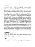
component of the molecular velocity V that increases the “te”. The energy level of this group
of molecules is raised as shown in Figure 32e. Thus, the total number of states do not change
even though the energy level for each group has increased due to work input. Now consider the
energy transfer due to heat (i.e. due to temperature difference) through solid walls into a gas
with the solid being at a higher temperature. The molecules within a group of gas molecules
impinging on the wall pick up the energy randomly and these can be placed at different energy
levels as shown in Figure 32c. The energy transfer through heat results in an entropy increase
while energy transfer through work does not. In Chapter 3 we will see that dS = δQ
rev
/T (but
not δW
rev
/T or PdV/T).
The entropy increases as two different species are mixed. This can be illustrated
through the example of two adjacent adiabatic containers of volumes V
1
and V
2
at the same
temperature that, respectively, contain nitrogen and oxygen. If the partition between them is
removed, then N
2
and O
2
gases have a new set of quantum states due to extension of volume
from V
1
and V
2
to V
1
+ V
2
. This increases the entropy of each species. Hence mixing causes
an increase in entropy, and, consequently the system entropy. In this instance, mixing causes
the entropy to increase even though total energy of nitrogen and oxygen is unchanged due to
mixing.
11. Properties in Mixtures – Partial Molal Property
A kmole of any substance at standard conditions contains 6.023x10
26
molecules
known as Avogadro number. The molecular energy is in the form of vibrational, rotational,
and translational energy, and the molecules are influenced by the intermolecular potential en-
ergy (ipe). At the standard state, the energy of pure water
¯u
is 1892 kJ/kmole (the bar at the
top indicates pure property on a kmole basis). If a kmole of water is mixed at the molecular
level at standard conditions with 2 kmoles of ethanol, each H
2
O molecule is now surrounded
by 2 molecules of ethanol. Since the temperature is unchanged, the intermolecular distance is
virtually unaltered before and after mixing. The attractive forces due to the water-ethanol
molecules are different from those between water-water molecules (this is true of non-ideal
solutions and will be discussed in Chapter 8) and, consequently, the potential energy is differ-
ent for the two cases. Therefore, the combined energy contribution to the mixture by a kmole
(or 6x10
26
molecules) of water in the mixture
^u
H2O,
is different from that of a kmole of pure
water
¯u
H2O
. The heat at the top of
¯u
H2O
indicates property when the component is inside the
mixture. Here,
^u
H2O
denotes the partial molar internal energy. Similarly, the enthalpy and
entropy of the water are different in the mixture from its unmixed condition. This is further
discussed in Chapter 8.
If the solution were ideal, i.e., if the ethanol-ethanol intermolecular attractive forces
were the same as those for water-water molecules, the water-ethanol attractive forces would
equal those in the pure states. In that case
^u
H2O
=
¯u
H2O
, for an ideal gas mixture and
µ
k
=µ
k
since attractive forces do not influence the property. However, even then,
^s
H2O
would not equal
¯s
H2O
, since the water molecules would be spread over greater distances in the
mixture with the result that the number of quantum states for water molecules would increase.
E. SUMMARY
We have briefly reviewed various systems (such as open, closed, and composite),
mixtures of substances, exact and inexact differentials and their relation to thermodynamic
variables, homogeneous functions and their relation to extensive and intensive variables, Tay-
lor series, the LaGrange multiplier method for optimization, and the Gauss and Stokes theo-
rems. The background material and mathematical concepts will be used through a quantitative
language useful to engineers involved with the design and optimization of thermodynamic
systems. We have also briefly covered the nature of intermolecular forces and potential, the
physical meanings of energy, pressure; of temperature, and of thermal, mechanical, and species
equilibrium; boiling and saturation relations; and, finally, entropy. These concepts are useful in
the physical interpretation of various thermodynamic relations that are presented in later chap-
ters.
F. APPENDIX
1. Air Composition
Species Mole % Mass %
Ar 0.934 1.288
CO
2
0.033 0.050
N
2
78.084 75.521
O
2
20.946 23.139
Rare gases 0.003 0.002
Molecular Weight: 28.96 kg kmole
–1
.
2. Proof of the Euler Equation
Assume that our objective is to determine a system property F, where
F(λx
1
, λx
2
, ) = λ
m
F(x
1
, x
2
, ), and (79a)
x
1,new
= λx
1
, x
2,new
= λx
2
, Differentiating Eq. (80) with respect to λ (and treating it as a vari-
able),
(∂F/∂(λx
1,new
))(∂x
1,new
/∂λ)+(∂F/∂(λx
2,new
))(∂x
2,new
/∂λ)+… = mλ
m–1
F(x
1
, x
2
, ). (81b)
Since ∂x
1,new
/∂λ = x
1
, ∂x
2,new
/∂λ = x
2
, …, Eq. (81b) assumes the form
(∂F/∂(λx
1,new
))x
1
+ (∂F/∂(λx
2,new
))x
2
+ … = mλ
m–1
F(x
1
, x
2
, ).
Multiplying both sides of the above equation by λ, and noting that
λ
m
F(x
1
, x
2
, ) = F(x
1,new
, x
2,new
, ),
we have the relation
(∂F/∂(λx
1,new
))x
1,new
+ (∂F/∂(λx
2,new
))x
2,new
+ … = mF(x
1,new
, x
2,new
, ). (80)
If m = 1,
xFx mF
k
k
K
k
=
∑
=
0
(/ )∂∂
. (81)
3. Brief Overview of Vector Calculus
a. Scalar or Dot Product
i. Work Done to Move an Object
Consider a surfboard being dragged over water along an elemental path
ds
r
by a
power boat that applies a force of
r
F
on the board. The work done is given as
δθWFdsF ds=⋅ =
r
r
cos
,
where θ denotes the angle between the force and the elemental path.
ii. Work Done to Move an Electrical Charge
Similarly if an electrical charge of strength Q is located at an origin, the force
r
F
ex-
erted by it on another charge of strength q situated at distance
r
r
removed from the origin is
r
r
FqQrr= ()/||ε
3
,
where ε denotes the Coulomb constant. If the product (qQ) > 0 (i.e., the two are like charges),
the force is repulsive. In case (qQ) < 0 (i.e., the charges are unlike) the force is one of attrac-
tion. The work done to move charge q away from Q
δWFdr=⋅
r
r
.
b. Vector or Cross Product
The area
r
A
due to a vector product
r
rr
Axy=×
, (82)
can be written in the form
rr
Akxy= | || | sinθ
, (83)
where
r
k
denotes the unit vector in a plane normal to that containing the vectors
r
x
and
r
y
, and
θ the angle between these two vectors. The vector product yields an area vector in a direction
normal to the plane containing the two vectors.
Consider the circular motion of an object around an origin in a plane. The force due to
that object in the plane
rr r r r
FiF jF iF jF
xy
=+= +cos sinθθ
, (84)
where θ denotes the angle between the force and an arbitrary x–wise coordinate at any instant,
and
r
i
and
r
j
denote unit vectors in the x– and y– directions, respectively. The torque exerted
about the center
rr
r
rr rrr
BFr iF jF ixjy kyF xF=×= + ×+= +( cos sin ) ( ) ( cos sin )θθ θθ
, (85)
where
rr
ii×
= 0,
rr
ij×
=
r
k
, and
rr
ji×
=
−
r
k
.
When a screw is loosened from a flat surface by rotating it in the counter clockwise
direction, it emerges outward normal to the surface, say, in the z–direction. To place the screw
back into the surface, it must be rotated in the clockwise direction, i.e., it may be visualized as
moving towards the origin of the z–direction. The rotation is caused by an applied torque that
is a vector. If the term (F cos θ y – Fsinθ x) = 0 in Eq.(87), then there is no rotation around the
z–axis. In general, a force has three spatial components, i.e.,
rr r r
FiF jFkF
xyz
=++
, (86)
and the torque is described by the relation
rr
r
rr r
B F r iFz Fy jFx Fz kFy Fx
yz z x xy
=×=+++++()()( )
, i.e., (87)
there are rotational components in the x– and y– directions also. If
r
F
and
r
r
are parallel to
each other, e.g.,
rr
FiF
x
=
and
r
r
rix=
, then
rr
r
BFr=×=0
.
c. Gradient of a Scalar
Consider a one–dimensional heat transfer problem in which the temperature T is only
a function of one spatial coordinate, say, y, i.e., T = T(y). In this case T(y) is a point or scalar
function of y, since its value is fixed once y is specified. In general, the gradient of T is defined
as
rrrr
∇=++Ti xjykzT(/ / /)∂∂ ∂∂ ∂∂
, (88)
which for the one–dimensional problem assumes the form
rr
∇=TjTy∂∂/
, (89)
The x–z plane contains isotherms, since T≠T(x,z), and
r
∇
T is a vector along normal to the
isotherms in the y–direction.
Consider, now, the temperature profile in an infinite cylindrical rod. Assume that the
temperature is constant along the axial direction z, once a cross–sectional location (x,y) is
specified, i.e., T=T(x,y), and T≠T(z). Assume an axisymmetric problem for which the iso-
therms are circular in the x–y plane and form cylindrical surfaces. In this case,
dT = (∂T/∂x)dx + (∂T/∂y)dy =
r
∇
T·
ds
r
, (90)
where ,
rr r
∇=+TiTxjTy∂∂ ∂∂//
. Therefore,
dT/ds =
r
∇
T·
ds
r
/ds, i.e., (91)
the gradient dT/ds varies, depending upon the direction of the gradient between any two iso-
therms. Along any circular isotherm
r
∇
T·
ds
r
= 0 according to Eq. (93), since
r
∇
T and
ds
r
are
normal to each other.
In general, if T=T(x,y,z) then isotherms form surfaces that lie in all three (x,y,z) coor-
dinates, and, at any location,
r
∇
T represents a vector that lies normal to a scalar surface on
which T is constant.
d. Curl of a Vector
Consider a vector
rrrrr rrr
∇×= + + × + +Fi xj ykz iFjFkF
xyz
(/ / /)( )∂∂ ∂∂ ∂∂
=−+−+−
rr r
iF z F y jF x F z kF y F x
yz zx xy
(/ /)(/ /)(/ /)∂∂∂∂ ∂∂∂∂ ∂∂∂∂
(92)
The LHS of Eq. (94) is a vector called curl
r
F
. If
rr
∇×F
= 0, then the two are parallel to each
other, i.e., the vector field is irrotational. Assume that
r
F
=
r
∇
T. (93)
Now assume that instead of a spatial coordinate system, x denotes pressure P, y denotes the
specific volume v, and z represents x
1
(i.e., the mole fraction of component 1 in a binary mix-
ture), i.e.,
rr r
r
r
∇×∇ = −
+−
+−
Ti xTv vTx
jPTx xTP
kvTP PTv
(/ (/) /(/ ))
(/(/ ) / (/))
(/(/) /(/)).
∂∂ ∂ ∂ ∂∂ ∂ ∂
∂∂ ∂ ∂ ∂∂ ∂ ∂
∂∂ ∂ ∂ ∂∂ ∂ ∂
11
11
(94)
The vector
r
∇
T lies in a direction normal to the isothermal surface T, and
r
∇
×
r
∇
T lies normal
to the plane containing
r
∇
and
r
∇
T. This implies that
r
∇
×
r
∇
T is a vector that lies back on the
isothermal scalar surface T, and, therefore,
r
∇
×
r
∇
T = 0. Note that the terms in the brackets
satisfy the criteria for exact differentials and the RHS of Eq. (96) equals zero. All thermody-
namic properties satisfy the irrotationality condition. Functions such as T=T(P,v,x
1
) are known
r
∇
as properties, point functions, scalar functions, or scalar potentials. Terms in exact differential
form, such as dT = ∂T/∂P dP + ∂T/∂v dv + ∂T/∂x
1
dx
1
, are called Pfaffians.
Chapter 2
2. FIRST LAW OF THERMODYNAMICS
A. INTRODUCTION
Chapter 1 contains an introduction to thermodynamics, provides some basic defini-
tions, a microscopic overview of thermodynamic properties and processes, and briefly reviews
the necessary mathematics. We will use that material to formulate thermodynamic laws based
either on a generalization of experimental observations, or in terms of four mathematical pos-
tulates that are not necessarily based on these experimental results. The laws of thermody-
namics are presented in Chapters 2 and 3, and the postulate concepts are addressed in Chapter
5.
The thermodynamic laws are simply restrictions on the transformation of energy from
one form into another. For examzple,
If the thermal energy content of a given mass of steam is 100,000 kJ, it is impossible to
obtain a work output of 150,000 kJ from it in the absence of another energy input. Here,
the First Law of Thermodynamics provides a restriction.
If that same mass of steam containing the same energy content exists at a temperature, it is
impossible to obtain a work output of 90,000 kJ from steam at 1000 K. In this case, the re-
striction is due to the second law of thermodynamics that constrains the degree of conver-
sion of heat energy.
In this chapter we will briefly discuss the zeroth and first laws that deal with energy
conservation, examine problems involving reversible and irreversible, and transient and steady
processes; and, finally, present the formulation of the conservation equations in differential
form. The second law and its consequences will be considered in Chapter 3.
1. Zeroth Law
The Zeroth law forms the basis for the concept of thermal state (or temperature). Con-
sider the body temperature of two persons (systems P
1
and P
2
) read using an oral thermometer
(system T). If the systems P
2
and T are in thermal equilibrium, and so are systems T and P
1
,
then systems P
2
and P
1
must exist at the same thermal state. Therefore, both persons will mani-
fest the same body temperature. Similarly, if the hot gas inside an electric bulb is in thermal
equilibrium both with the electrical filament and the glass wall of the bulb, the glass wall is
necessarily in thermal equilibrium with the filament.
2. First Law for a Closed System
We will present the First law of thermodynamics for a closed system, and illustrate
applications pertaining to both reversible and irreversible processes.
a. Mass Conservation
For closed systems the mass conservation equation is simply that the mass
m = Constant, (1)
In the field of atomic physics, mass and energy E are considered convertible into each another
and, taken together, are conserved through the well–known Einstein relation E = mc
2
, where c
denotes the light speed. However, in the field of thermodynamics it is customary to assume
that the conversion of mass and energy into each other is inconsequential and, therefore, either
is separately conserved.
b. Energy Conservation
An informal statement regarding energy conservation is as follows: “Although energy
assumes various forms, the total quantity of energy is constant, with the consequence that
when energy disappears in one form, it appears simultaneously in others”.
i. Elemental Process
For a closed system undergoing an infinitesimally slow process, (Figure 1a) during
which the only allowed interactions with its environment are those involving heat and work,
the first law can be expressed quantitatively as follows
δQ – δW = dE, (2)
where δQ denotes the elemental (heat) energy transfer across the system boundaries due to
temperature differences (Figure 1a), δW the elemental (work) energy in transit across the
boundaries (e.g., the piston weight lifted due to the expansion of the system), and dE the en-
ergy change in the system. The "E" includes internal energy U (=TE+VE+RE etc.) which re-
sides in the matter, kinetic energy KE and potential energy PE. Note that Q and W are transi-
tory forms of energy and their differentials are written in the inexact forms δQ and δW (see
Chapter 1) while differential of resident energy E is written as an exact differential. Dividing
Eq. (2) by m,
δq – δw = de, (3a)
where q denotes the heat transfer per unit mass Q/m, w the analogous work transfer W/m, and,
likewise, e = E/m.
It is customary to choose a sign convention for the work and heat transfer that follows
common sense. In the absence of work transfer, i.e., δW = 0, addition of heat causes an in-
crease in energy. Therefore, it is usual to accord a positive sign for heat transfer into a system.
For an adiabatic system (δQ = 0), if the work done by the system is finite and conferred with a
positive sign (W > 0), then, from Eq. (2), dE < 0. This is intuitively appropriate, since in order
to perform work, the system must expend energy. On the other hand, if the system of Fig. 2 is
adiabatically compressed, work is done on the system (so that W < 0), and the stored energy in
the system increases (dE > 0).
The system energy consists of the internal, potential, and kinetic energies. Equation
(2) may be rewritten for a static system in the form
δQ – δW = dU. (3b)
ii. Internal Energy
At a microscopic level the internal energy is due to the molecular energy which is the
sum of the (1) molecular translational, vibrational and rotational energies (also called the ther-
mal portion of the energy), (2) the molecular bond energy (also called the chemical energy),
and the (3) intermolecular potential energy, ipe (cf. Chapter 1). At a given temperature the
energy depends upon the nature of a substance and, hence, is known as an intrinsic form of
energy.
iii. Potential Energy
The potential energy of a system is due to the work done on a system to adiabatically
move its center of gravity through a force field. The potential energy of a system whose center
of gravity is slowly raised vertically (so as not to impart a velocity to it) in the earth’s gravity
field through a distance of dz increases by a value equal to mgdz. The first law
δQ - δW = dU + d(PE) + d(KE),
where PE and KE denote the potential and kinetic energies, can be applied after noting that for
this case δQ = dU = d(KE) = 0, so that
0 – δW = 0 + d(PE) + 0. (4)
Now, δW = –F dz. The negative sign arises since work is done on the system by a force F that
lifts it through a distance dz. In raising the mass, the direction of the force is vertically upward.
In the absence of any acceleration of the mass, this force is also called a body force. Using the
relation F = mg for the force with g denoting the local gravitational acceleration, the work
done W = –mg dz, and using Eq. (4) d(PE) = –δW = mg dz. Integrating this expression across
a vertical displacement that extends from z
1
to z
2
, the potential energy change is given as
∆PE = mg(z
2
– z
1
).
The potential energy per unit mass due to the gravitational acceleration at a location z
above a stipulated datum is also called the gravitational potential pe, i.e.,
pe = gz. (5)
In SI units, pe can be expressed in J kg
–1
or in units of m
2
s
–2
, where
pe (in units of kJ kg
–1
) = g(in units of m s
–2
) z(in units of m)/1000.
In English units, pe can be expressed as BTU lb
–1
= g(ft s
–2
) z(ft)÷(g
c
J), where g
c
= 32.174 (lb
ft s
–2
lbf
–1
) is the gravitational constant, and J denotes the work equivalent of heat of value
778.1(ft lbf BTU
–1
).
iv. Kinetic Energy
In order to move a mass along a level frictionless surface, a boundary or surface force
must be exerted on it. Applying the first law, namely, δQ - δW = dU + d(PE) + d(KE), the
adiabatic work due to these forces can be expressed as
0 – δW = 0 + 0 + d(KE). (6)
The work performed in moving the center of gravity of a system through a distance dx is (– F
dx), where the force F = m dV/dt, the velocity V = dx/dt, and t denotes time. In order to be con-
sistent with the standard sign convention, the work done on the system is considered negative.
Therefore, d(KE) = m (dV/dt)×(V dt) = mVdV. Upon integration, the kinetic energy change of
the system as it changes its velocity from a value V
1
to V
2
is
∆KE = (1/2)m(
VV
2
2
1
2
−
).
The kinetic energy per unit mass ke is
ke =1/2 V
2
.(7)
In SI units, ke is expressed in J kg
–1
, namely, ke(J kg
–1
) = (1/2)V
2
(m
2
s
–2
). Often, it is prefer-
able to express ke as
ke (kJ kg
–1
) = (1/2000)V
2
.
In English units, ke(BTU lb
–1
) = V
2
(ft
2
s
–2
)÷(g
c
J). The kinetic and potential energies are inde-
pendent of the nature of the matter within a system, and are known as extrinsic forms of en-
ergy.
v. Integrated Form
Integrating Eq. (2) between any two thermodynamic states (1) and (2) we have
Q
12
– W
12
= E
2
– E
1
= ∆E. (8)
The heat and work transfers are energy forms in transit and, hence, do not belong to the matter
within the system with the implication that neither Q nor W is a property of matter. Therefore,
while it is customary to write the energy change for a process E
12
= E
2
–E
1
, we cannot write Q
12
= (Q
2
–Q
1
) or W
12
= (W
2
–W
1
). Since for a cycle the initial and final states are identical,
δ
∫∫
=QW
=0.
Writing Eq. (8) on a unit mass basis
q
12
– w
12
= e
2
– e
1
= ∆e. (9)
The application of the first law to systems require these to be classified as either cou-
pled systems in which the transit energy modes, namely, Q and/or W, affect particular storage
forms of energy, or as uncoupled systems if the heat and/or work transfer affect more than one
mode of energy as illustrated below.
vi. Uncoupled Systems
Consider an automobile that is being towed uphill on a frictionless road during a
sunny summer afternoon from initial conditions Z
1
= V
1
= U
1
= 0 to an elevation Z
2
, velocity
V
2
and energy U
2
. Taking the automobile as a system, the heat transfer Q
12
from the ambient to
the car is determined by applying Eq. (8), i.e.,
Q
12
– W
12
= E
2
– E
1
= ∆U + ∆PE + ∆KE,
so that Q
12
= ∆U. Therefore, the heat transfer across the boundary increases the system internal
energy by ∆U which changes the static state of the system. The work performed to tow the
automobile is
– W
12
= ∆ PE + ∆ KE,
which influences the dynamic state of the system.
a. Example 1
A car of mass 2000 kg is simultaneously accelerated from a velocity V = 0 to 55 mph
(24.6 m s
–1
) and elevated to a height of 100 m. Determine the work required. Treat the
problem as being uncoupled.
Solution
Q
12
– W
12
= = U
2
– U
1
+ KE
2
– KE
1
+ PE
2
– PE
1
.
0 – W
12
= (0+(2000÷2)(24.6 m s
–1
)
2
–0+2000×(9.81×100)–0)÷1000 = 2568 kJ.
Remark
All of the work can be recovered if the car is made to slide down on a frictionless
road to ground level (i.e., to zero potential energy) so that the potential energy is completely
converted into kinetic energy. Upon impact against a spring the vehicle kinetic energy is fur-
ther transformed into the spring potential energy, thereby recovering the work. Hence, the
process is uncoupled.
vii. Coupled Systems
In coupled systems two or more interactions across the system boundary (e.g., heat
and work) influence the same energy mode. For example, if a tow truck pulls a car on a rough
high-friction road, the work performed is higher than that for an uncoupled system, since addi-
tional work is required in order to overcome the external friction. Frictional heating can cause
the internal energy of the car tires to increase, and if the tires do not serve as good insulators,
heat transfer to the road can occur. Therefore, the work is coupled with both internal energy
and heat transfer. This is illustrated in the following example.
b. Example 2
A car of mass 2000 kg that is simultaneously accelerated from a velocity V = 0 to 55
mph (24.6 m s
–1
) and elevated to a height of 100 m requires a work input of 3000 kJ.
If the car is well insulated, what is the change in the internal energy of the car?
Solution
Q
12
– W
12
= = U
2
– U
1
+ KE
2
– KE
1
+ PE
2
– PE
1
.
0+3000=U
2
–U
1
+((2000÷2)(24.6ms
–1
)
2
–0+2000×(9.81×100)–0)÷1000=2568 kJ,
i.e.,
U
2
– U
1
= 3000 – 2568 = 432 kJ.
Remarks
The work input is more than ∆KE and ∆PE. Thus additional work is used to over-
come friction. Frictional work results in heating. If the tires (which are part of the car)
are well insulated, their internal energy increases by 432 kJ. In this case the work is
coupled to changes in the internal, kinetic, and potential energies of the system.
Dividing the work into intrinsic and extrinsic contributions
W
12
= W
12,int
+ W
12
,
ext
,
we find that W
12,int
= 432 kJ, which results in the change in U, and that W
12
,
ext
= 3000
– 432 = 2568 kJ, which results in a change in the kinetic and potential energies,
(diathermic) and the tire remains at fixed temperature. Then there is no change in the
internal energy. Hence heat must be lost from the tires, i.e.,
Q
12
– W
12
= ∆U + ∆PE + ∆KE = 0 + ∆PE + ∆KE,
where Q
12
= –432 kJ, and W
12
= –3000 kJ. In this case the work is coupled with the
heat transfer. The heat transfer affects the intrinsic energy by changing U.
When the car moves at a high velocity, frictional drag due to the atmosphere can
cause its body to heat, thereby increasing the internal energy. The work done on the
car also increases its potential and kinetic energies, and the process becomes coupled.
The work cannot be recovered, since the car will contain a higher internal energy
even after impacting it against the spring, as illustrated in the previous example.
The heating of matter offers another example involving a coupled system. Consider
constant pressure heating that causes a system of gases to expand and lift a weight of 100 kg
through a distance of 2 m, if Q
12
= 10 kJ, W
12
= 1.96 kJ. (Here we neglect any change in the
center of gravity of the matter contained in the system.) If there is no change in the system
kinetic energy, from Eq. (8)
Q
12
– W
12
= U
2
– U
1
= ∆U. (10)
In this case Q
12
≠ ∆U. As a result of the work and heat interaction, ∆U = 10 – 1.96 = 8.04 kJ. If
the system is confined to include only the moving boundary and the lifted weight, and these
are considered adiabatic, then (–W
12
) = ∆(PE), so that the work performed alters the system
potential energy.
The illustrations of coupled and uncoupled systems demonstrate that it is necessary to
understand the nature of a problem prior to applying the mathematical equations.
c. Systems with Internal Motion
Consider a mass of warm water contained in a vessel. If it is stirred, the entire effort
imparts kinetic energy to that mass in the absence of frictional forces, and the center of gravity
of each elemental mass of water moves with a specific kinetic energy ke. If the kinetic energy
distribution is uniform throughout the system, its total value equals m x ke. Such a situation
exists in an automobile engine when fresh mixture is admitted or when the exhaust valve
opens. Oftentimes, the kinetic energy is destroyed due to internal frictional forces between the
system walls and moving matter, which converts the kinetic energy into internal energy, as in
coupled systems.
viii. Adiabatic Work and Caratheodary Axiom I
The work performed during all adiabatic processes (Q
12
= 0) between two given
states is the same. Applying Eq. (8)
W
12
= E
2
– E
1
= ∆E.
This statement is called the Caratheodary Axiom I (see Postulate III of Chapter 5). For exam-
ple, the electrical work (= voltage × charge current) used to heat a fluid adiabatically between
two temperatures is identical to the mechanical work (e.g., performed using a pulley–paddle
assembly to stir the water) required for a similar adiabatic heating process.
d. Cyclical Work and Poincare Theorem
ix. Cyclical Work
For a closed system undergoing a thermodynamic cyclical process,
Boiler
Pump
Turbine
condenser
atmosphere
300kJ
W
net
=1000kJ
200kJ 500kJ400kJ
combustor
Generator
system
dZ
Q
δ
W
δ
(a)
(b)
Figure 1: Illustration of the first law for a cyclical process.
dE
∫
= 0. (11)
Hence, the first law (Eq. (2)) yields,
δδQW
∫∫
=
, (12)
and Eq. (12) implies that if
δQ
∫
≠0, then
δW
∫
≠0. On a unit mass basis
δδqw
∫∫
=
.
Figure 1b illustrates the cyclical process in a steam power plant for which the heat transfer
during the various processes is indicated. Applying Eq. (12) for all processes, i.e., 1–2, 2–3,
3–4, , and 8–1,
δδQQ Q Q WW W W
∫∫
===+++
+++
12 23 81 12 23 81
L
L
,
so that
δW
∫
= 0 –300 – 2000 + 0 + 0 –200 + 0 + 4000 – 500 = 1000 kJ.
Therefore, by considering the net heat transfer for this cyclical process, the net work output of
the plant can be determined.
x. Poincare Theorem
Consider an adiabatic system containing water and a mechanical stirrer. Work transfer
through the stirrer is used to
raise the water temperature
from a quiescent state 1 to an-
other motionless state 2. Since
Q
12
= 0, the change in internal
energy can be obtained by ap-
plying the first law (Eq. (10)),
and U
2
– U
1
= ∆U = |W
12
|.
Next, if the insulation is re-
moved and the water allowed
to cool to its initial state,
Eq.(10) can again be used to
determine the heat flow Q
21
. In
this case Q
21
= |U
2
– U
1
| =
|W
21
| as a consequence of the
Poincare theorem of thermo-
dynamics, which states that
during a cyclical process the
net heat interactions equal the
net work interactions. While
the Caratheodary axiom states the First Law in context of a single adiabatic process, the Poin-
care theorem expresses it for a cyclical process.
xi. Rate Form
Equation (2) can be used to express the change in state over a short time period δt
(i.e., δQ =
˙
Q
δt, and δW =
˙
W
δt to obtain the First Law in rate form, namely,
˙
Q
–
˙
W
= dE/dt. (13)
b
c
a
Figure 2: P–v diagram for quasiequilibrium and nonquasie-
quilibrium processes.
The rate of work
˙
W
is the energy flux crossing the boundary in the form of macro-
scopic work (e.g., due to the system boundary motion through a distance dz as illustrated in
Figure 2). The heat flux
˙
Q
is a consequence of a temperature differential, and does not itself
move the boundary, but alters the amplitude of molecular motion that manifests itself in the
form of temperature.
We see that energy conservation can be expressed in various forms (e.g., Eqs. (2), (3),
(8), (9), (12) and (13)). The laws of thermodynamics are constitutive equation independent. It
is possible to determine dE/dt accurately if
˙
W
and
˙
Q
are measured. Calculations of
˙
Q
and/or
˙
W
may require constitutive relations. In the context of the relation
˙
Q
= - λ∇T, a constitutive
equation for heat transfer is employed with
˙
W
= 0. Therefore, the value of dE/dt depends upon
the accuracy of the Fourier law and can differ from actual experimental data.
e. Quasiequilibrium Work
Consider an adiabatic frictionless piston–cylinder assembly on which infinitesimal
weights are placed as illustrated in Figure 3a and Figure 3b. If the small weights are slowly
removed, the system properties remain almost uniform throughout the removal process. There-
fore, at any instant following the removal of an infinitesimal weight, if the system is isolated, it
is in an equilibrium state (i.e., its properties are invariant with respect to time). Since the inten-
sive state can be determined during any part of the process involving the successive removal of
weights, the path along which the process proceeds can be described (e.g., as illustrated in
Figure 2 for a quasiequilibrium process that moves the system from state 1 to 2R along the
path ABC). Due to their nature, quasiequilibrium processes are also termed quasistatic.
However, not all quasistatic processes are at quasiequilibrium. Consider the example
of a gasoline–air mixture (system) contained in a piston–cylinder assembly. At the end of a
compression process, spark is initiated, hot region develops around the spark plug, while the
remainder of the mixture is much colder. Even though the piston moves slowly (i.e., it is qua-
sistatic) during this process, the spark initiation results in a non–equilibrium state, since the
temperature distribution is nonuniform, and it is not possible to assign a single system tem-
perature.
The consequences of the quasiequilibrium processes illustrated in Figure 3 are as fol-
lows:
If the infinitesimal weights are slowly removed, then at any time the force of the weights F
≈ PA, where A denotes the piston surface area. A force of P×A is exerted by the system.
Therefore, the infinitesimal work W performed by the system as the individual weights are
removed, and the piston moves infinitesimally through a displacement dx, is
P
2
V
2
P
2R
V
2R
P
A
V
A
P
1
V
1
P
1
V
1
Figure 3: a. Quasiequilibrium process; b. Nonquasiequilibrium process.
δW = F dx = PAdx = PdV. (14)
Consequently, the work done during the process 1–2 is
W
12
=
PdV
1
2
∫
. (15)
This is an illustration of reversible work.
The work performed by the system results in a p\otential energy gain for the remaining
weights that are placed in the environment outside the system.
Since energy is transferred to the environment, according to the first law the system loses
internal energy. The process can be reversed by slowly placing the weights back on the
piston. This action will push the piston inward into the system, reduce the potential energy
of the weights placed in the system environment, and restore the system to its initial state.
A quasiequilibrium process is entirely reversible, since the initial states of both the system
and environment can be completely restored without any additional work input or heat in-
teraction.
We will see later that a totally reversible process is always a quasiequilibrium process.
The work done on or by the system PdV is due to the matter contained within it. The sign
convention follows, since it is positive
for expansion (when work is done by the
system), and negative during compres-
sion (when work is performed on the
system).
It can be mathematically shown that W
is an inexact differential. Equation (14)
may be written in the form δW = PdV +
0×dP. Using the criteria for exact differ-
entials (discussed in Chapter 1) with M
= P, and N = 0, it is readily seen that
∂M/∂P = 1, and ∂N/∂V = 0. Therefore,
∂M/∂P ≠ ∂N/∂V.
c. Example 3
Air is isobarically expanded from
state 1 (P
1
= 1 bar, v
1
= 1 m
3
kg
–1
),
to state 2 (P
2
= 1 bar, v
2
= 3 m
3
kg
–1
), and then compressed isometrically to state 3 (P
3
= 3 bar, v
3
= 3 m
3
kg
–1
). De-
termine the final temperature and the net work.
Air is isometrically compressed from state 1 (P
1
= 1 bar, v
1
= 1 m
3
kg
–1
), to state 4 (P
4
= 3 bar, v
4
= 1 m
3
kg
–1
), and then expanded isobarically to state 3 (P
3
= 3 bar, v
3
= 3
m
3
kg
–1
). Determine the final temperature and the net work.
Solution
The P–v diagram for this example is illustrated in Figure 4. The final temperature T
3
is independent of the work path, and
T
3
= P
3
v
3
/R = 300×3÷0.287 = 3136 K.
The work along the two paths
w
123
= P
1
(v
2
– v
1
) = 1 × 100 × (3 – 1) = 200 kJ kg
–1
, and (A)
w
143
= P
4
(v
3
– v
2
) = 3 × 100 × (3 – 1) = 600 kJ kg
–1
. (B)
1
4
3
2
V
P
Figure 4: P–v diagram with P expressed in
units of bar and v in m
3
kg
–1
.
Remarks
The net work in the second case, i.e., w
143
, is larger compared to W
123
. The tempera-
ture represents the state of the system, and its functional form, e.g., T
3
= P
3
v
3
/R, is in-
dependent of the path selected to reach that state. However, the work expressions w
123
and w
143
(Eqs. A and B) depend upon the path selected to reach the same final state,
even though the expressions for work (contain variables that only represent proper-
ties. Therefore, the final temperature is path independent, but the net work is not.
The inexact differential W integrated between two identical states along dissimilar
paths 1–2–3 and 1–4–3 yields different results. An inexact differential can only be
integrated if its path is known.
f. Nonquasiequilibrium Work
In the context of Figure 3, the initial pressure in the system is such that P
1
A = F
1
,
where F
1
denotes the combined weight of the piston and the aggregate weights placed upon it.
If all of the weights are abruptly removed, rather than slowly as discussed previously, the force
exerted on the system near the piston will be much smaller than F
1
. The difference between
these two forces results in an acceleration of the piston due to Newton’s law, and the piston
mass acquires kinetic energy. Thereupon, the system pressure in the vicinity of the piston rap-
idly decreases. The translational energy of these molecules decreases with the pressure reduc-
tion.However, molecules further removed from the piston still possess their initial velocities
(i.e. higher T, higher P), and the system is in an internally nonequilibrium state. The matter
adjacent to the piston also acquires kinetic energy (e.g., Section A in Figure 5) while that re-
moved from it does not (e.g., Section B). Hence at any instant the system properties are non-
uniform and, consequently, the process is not at quasiequilibrium.
The time taken for the system to equilibrate, also called its relaxation time t
relax
, is of
the order of the distance divided by average molecular velocity (that approximately equals the
sound speed V
s
). Typically, the sound speed in air at room temperature is 350 m s
-1
. It follows
that if L = 10 cm, t
relax
= 3Η10
-3
s. Consequently, a disturbance near the piston, such as a de-
creased pressure or decreased molecular velocity is communicated through random molecular
motion to molecules located 10 cm away after roughly 0.3 ms. If the piston is displaced by 10
P
2
V
2
P
2
V
1
2
F E
D
P
D,b
=P
1
P
0,a
<P
1
a
P
0
V V
dime
box
Figure 5: Illustration of a nonquasiequilibrium process.
cm every 0.3 ms, the disturbance perpetuates, and a non-equilibrium condition continually
prevails.
This behavior is similar to that of a disturbance due to stones dropped into a placid
pond. The disturbance is always present unless the time interval between two sequentially
dropped stones is long. If the rate of stones being dropped is fast enough, the disturbance
strengthens. In the piston–cylinder example, if the piston moves with a velocity of 1 m s
–1
(which is much lower than the sound speed), the typical time scale involving motion through a
10 cm displacement (=L/V
P
) is 100 ms, which is much larger than the relaxation time. In this
case, the pressure rapidly conforms to a uniform value within the whole system. Therefore, a
process may be assumed to be in quasiequilibrium as long as its relaxation timescale (=L/V
s
) is
considerably smaller than the process timescale (=L/V
P
) responsible for the property gradients
that are the source of nonequilibrium system conditions. If V
P
= 350 m s
–1
, quasiequilibrium
cannot be assumed, and the system properties (i.e., its state) along the process path cannot be
described. Therefore, an uncertain path is used to illustrate such a process in Figure 2.
During the quasiequilibrium process 1–2R described in Figure 2, the system performs
more work than any corresponding non-equilibrium process 1–2 (path D-E-F-2), since part of
the non-equilibrium work imparted to the piston in the form of kinetic energy is converted into
thermal energy. As a consequence, even if expanded to the same final volume, the temperature
at the end of a non-equilibrium process is higher, and applying the ideal gas law P
2
> P
2R
(state
2). This may also be understood by envisioning the frictional effects that dissipate and raise the
system internal energy (therefore, temperature) during non-equilibrium processes. These proc-
esses are irreversible, since the original system state cannot be reverted to its original state by
simply reversing the work transfer. An additional amount of work is required to overcome the
effects due to friction.
Placing the system boundary immediately around the piston and the external weights
(that are respectively, of mass m
p
and m
w
), the force experienced by the system is
m dV
P
/dt = P
b
A – P
R
A, (16a)
where dV
P
/dt denotes the piston acceleration, P
b
the pressure at the system boundary, P
R
= P
o
+
mg/A is the sum of the ambient pressure and the pressure due to the piston weight, and m = m
p
+ m
w
. The work performed to move the accelerating mass m through a displacement dz is the
difference between the work performed by the system and that performed to overcome the
resistance to its motion. Multiplying Eq. (16a) by dZ
m (dV
P
/dt) dz = δW – (P
o
dV + mg dz),
where the boundary work δW = P
b
dV. Therefore,
δW = m (dV
P
/dt) dz + P
o
dV + mg dz. (16b)
Using the relation dz = V
P
dt in Eq. (16a), and integrating appropriately,
W = m ∆ke + P
o
∆V + m∆pe, (17)
where P
o
ke = V
P
2
/2 and ∆pe = gz.
If the system pressure is uniform (e.g., t
relax
« L/V
p
), then P
b
= P and the work per-
formed by system
δW ≈ PdV,
which requires a functional relation between P and V for the matter contained in the system.
The following example illustrates a nonquasiequilibrium process.
d. Example 4:
A mass of air is contained in a cylinder at P = 10 bar, and T = 600 K. A mass of 81.5
kg is placed on the piston of area 10 cm
2
and the piston is constrained with a pin. If
the pin is removed,
assuming the piston
mass and atmospheric
pressure to be negligi-
ble:
Determine the piston
acceleration just after
the pin is released.
Write an expression
for the work per-
formed on the sur-
roundings.
Write an expression
for the work done by
the system matter if it
exists at a uniform
state.
Why is there a differ-
ence between the an-
swers to the questions
above?
What are the effects of a frictional force of 0.199 kN? (See also Figure 6.)
Solution
The force due to mass of 81.5 kg placed on the piston equals 81.5×9.81÷1000 = 0.8
kN. The pressure due to a weight of 0.8 kN equals 800 kPa (or 8 bar). Since the sys-
tem pressure is 10 bar, there is a force imbalance equivalent to 2 bars, and the mass is
accelerated. The force F = m×a = mdV/dt, i.e.,
F = (10–8)bar×100 kN m
–2
bar
–1
×10 cm
2
×10
–4
m
2
cm
–2
×1000 N kN
–1
= 200 N.
Hence, the initial acceleration dV/dt = F/m = 2.45 m s
–2
.
The work δW = 800×dV, which changes the potential energy of the mass.
If the process is internally reversible, the matter is internally in a quasiequilibrium
state, and δW = PdV.
The difference between the work performed by the system and that transmitted to the
weight in the form of potential energy increases the kinetic energy of the weight. If
the imparted kinetic energy is zero (or dV/dt = 0), the work done by the system equals
that done on its surroundings, i.e., there are no losses.
In the case of a frictional force of 0.199 kN, the resistance force F = 0.8 + 0.199 =
0.999 kN so that the resistance pressure P = 0.999 kN /10
–3
m
2
= 999 kPa, which is
virtually identical to the system pressure. Therefore, the force imbalance is negligible,
and m dV/dt ≈ 0. If the process is internally reversible, the work done by the system
δW
system
= P dV, and that done on the weight δW
W
≈ 800×dV. Hence, the frictional
work
W
F
= P dV – 800×dV = (P – 800) ×dV.
e. Example 5
A mass of 50 kg is placed on a 10 cm
2
area weightless piston (cf. Figure 7). The am-
bient is a vacuum, i.e., the pressure is zero in it. The initial gas pressure is 100 bar,
and the initial volume is 10 cm
3
. The cylinder height is 10 cm. A pin, constraining the
piston in place is suddenly released.
2
Piston area
A=10cm
3
10 bar
600 K
81.5 kg
81.5 kg
Figure 6: A nonquasiequilibrium process due to the release
of a mass accelerated by a pressurized system.
Consider the gases in the piston–cylinder assembly to constitute a system A. If the
process in system A is internally reversible and isothermal, determine the work output
of the gas.
Let system B be such that it includes the piston, weight, and ambient, but excludes the
gases. What is the velocity of the piston when its position is at the cylinder rim? As-
sume system B to be adiabatic.
Solution
System A delivers work to system B during the process 1–2.
V
1
= 10 cm
3
, V
2
= 10 cm × 10 cm
2
= 100 cm
3
.
The work done by system A is:
W
A
= ∫PdV = ∫(mRT/V)dV = mRT ln(V
2
/V
1
) = P
1
V
1
ln(V
2
/V
1
) (A)
∴ W
A
= 100 bar × 100 kN m
–2
bar
–1
× 10 cm
3
× 10
–6
m
3
cm
–3
ln(100/10)
= 0.230 kJ.
The work input from system A into system B results in an increase of the kinetic and
potential energies of the weight. The initial and final heights of the piston in the cyl-
inder are:
Z
1
= V
1
/A = 10 cm
3
÷ 10 cm
2
= 1 cm, Z
2
= 10 cm. (B)
Applying Eq. (8) to system B, i.e.,
Q
12
– W
12
= E
2
– E
1
= ∆U + ∆PE + ∆KE, (C)
where ∆PE = 50 kg×9.81 m s
–2
×(10–1)cm×0.01 m cm
–1
÷ (1000 J kJ
–1
) = 0.044 kJ,
and
∆U = 0.
Using this result and Eq. (A) in Eq. (C),
0 – (–0.230) = 0 + ∆KE + 0.044, i.e.,
∆KE = (1/2)m(V
2
2
– V
1
2
) = 0.230 – 0.044 = 0.186 kJ.
Since the initial velocity V
1
is zero, (1/2)mV
2
2
/1000 = 0.186 kJ, and substituting
m=50 kg,
V
2
= 2.73 m s
–1
.
Remarks
Instead of
the 50 kg
weight, a
projectile of
very small
mass can be
similarly
used. If the
projectile
were fired
from the
chamber
using, say,
gunpowder,
the gases
would ex-
pand, al-
though the
Z
1
Z
2
V
P
(1)
(2)
B
A
Figure 7: An analysis of a nonequilibrium process.
high temperature would remain unchanged over the period of interest due to the com-
busting powder. In that case, the projectile velocity can be determined using the
above example.
Since the velocity in the example is of the order of 2.73 m s
–1
, which is much slower
than the room temperature molecular velocity of 350 m s
–1
, one can assume rapid
equilibration within the system. However, at lower temperatures, the quasiequilibrium
assumption is invalid, since the molecular velocity can approach the process velocity.
If the ambient pressure P
o
is 1 bar, the work transmitted to the matter, which is also
called useful work, is given by the relation
W
u
= ∫PdV – ∫P
o
dV = ∫(P – P
o
)dV = ∫PdV – P
o
(V
2
– V
1
), i.e.,
W
u
= 0.230 – 1 × 100 × 90 × 10
–6
= 0.221 kJ.
Therefore, the kinetic energy change is
∆KE = (0.221 – 0.044) = 0.177 kJ, and
V
2
= (2 × 1000 × 0.177 ÷ 50)
1/2
= 2.66 m s
–1
.
g. First Law in Enthalpy Form
If the kinetic and potential energies are neglected, Eq. (2) transforms into
δQ – δW = dU.
The enthalpy can replace the internal energy in this equation. The enthalpy of any substance is
defined as
H = U + PV, or (18)
h = u + Pv.
For ideal gases PV = mRT and, hence, H = U + mRT. Substituting Eq. (18) in Eq. (3’)
δQ – δW = d(H – PV).
For a quasiequilibrium process δW = PdV + δW
other
. Therefore,
δQ – PdV – δW
other
= d(H – PV).
Simplifying, this expression
δQ + VdP – δW
other
= dH. (19)
If δW
other
= 0
δQ + VdP = dH.
The First Law can be written in the form
δQ– δW' = dH,
where for a reversible process
δW' = – VdP.
For a quasiequilibrium process at constant pressure
δQ
P
= dH. (20)
If an electric resistor is used to heat a gas contained in an adiabatic piston–cylinder–weight
assembly, as shown in Figure 8b, the constant pressure electrical work
–δW
elec,P
= dH. (21)
The constant volume work (cf. Figure 8a) is
–δW
elec
= dU. (22)
Note that the First Law is valid whether a process is reversible or not. However, once the
equality δW = P dV is accepted, a quasiequilibrium process is also assumed.
xii. Internal Energy and Enthalpy
Experiments can be performed to measure the internal energy and enthalpy using Eqs.
(21) and (22). For instance, electrical work can be supplied to a fixed volume adiabatic piston
cylinder assembly (cf. Figure 8a), and Eq. (22) used to determine the internal energy change
dU or du. Alternately, using a constant pressure adiabatic assembly (cf. Figure 8b), the electric
work input equals the enthalpy change, and Eq. (21) can be utilized to calculate dH or dh.
The internal energy is the aggregate energy contained in the various molecular energy
modes (translational, rotational, vibrational) which depend upon both the temperature and the
intermolecular potential energy which is a function of intermolecular spacing or volume (see
Chapter 1). Therefore, u = u(T,v) or u = u(T,P), since the specific volume is a function of pres-
sure. While differences in internal energy can be determined, its absolute values cannot be
obtained employing classical thermodynamics. However, we are generally interested in differ-
ences. For tabulation purposes a reference condition is desired. If the initial condition u
1
= u
ref
is the reference condition and u
2
= u during a process 1–2, the difference
∆u = u(T,P) – u
ref
(T
ref
,P
ref
).
We normally set u
ref
= 0 at the reference temperature and pressure T
ref
, and P
ref
, which
characterize the reference state. For example, for tabulation of steam properties, the triple point
(T
tp
= 0.01ºC, P
tp
= 0.006 bar) is used as the reference state. Once u is calculated with respect
to the reference condition u
ref
= 0, Eq. (18) can be used to determine h. From the relation
h
ref
= u
ref
+ P
ref
v
ref
= 0 + P
ref
v
ref
.
A
diabatic work addition -
constant pressure
A
diabatic work addition -
c
onstant volume
Figure 8: (a) Constant volume, b) Constant pressure processes.
we note that h
ref
≠ 0 even though u
ref
= 0. However, a separate reference condition can be used
for the enthalpy so that
∆h = h(T,P) – h
ref
(T
ref
,P
ref
).
The internal energy can be separately calculated at this reference state. Property tables for
many substances set h
ref
= 0 at (T
ref
,P
ref
) (Steam tables usually use T
ref
= 0.01 C and P
ref
=
0.0061 bar for liquid water).
f. Example 6
One kilogram of water at a temperature T = T
ref
= T
tp
= 0.01ºC is contained in an
adiabatic piston cylinder assembly. The assembly resides in an evacuated chamber
and a weight is placed on top of the piston such that P = P
ref
= 0.61 kPa. At these ref-
erence conditions, the specific volume v(T
ref
,P
ref
) = 0.001 m
3
kg
–1
is assumed to be in-
dependent of temperature. During an isobaric process, a current of 0.26 A provided at
a potential of 110 V over a duration of 60.96 min raises the water temperature to
25ºC. Determine the enthalpy of water at that state if h
ref
= 0.
Solution
We will use the energy conservation equation
δQ – δW = dU
and select the water mass as the system. In general, the work term will include a
volumetric change component in addition to the electrical work so that
δQ – PdV – δW
elec
= dU.
At constant pressure, δQ
P
– δW
elec,P
= dU + PdV = dH, and on a unit mass basis
δq
P
– δw
elec,P
= du + Pdv = dh.
Recalling that the system is adiabatic (q
P
= 0), and integrating the latter expression
– w
elec,P
= h – h
ref
.
Now, W
elec
= 0.26 × 110 × 60.96 × 60 = 104.6 kJ. Therefore, – (–104.6) = h – 0, and
h (25ºC, 0.61 kPa) = 104.6 kJ kg
–1
.
Furthermore,
u = h – Pv = 104.6 – 0.61 × 0.001 ≈ 104.6 kJ kg
–1
.
Remarks
The experiments may be repeated at different pressures for the same temperature
range, and the enthalpy tabulated as a function of pressure. If the specific volume is
known, applying the relation u = h – Pv, the internal energy can also be tabulated, as
is done in the Steam tables.
Through experiments performed on ideal gases, it is found that h = h(T) which is in-
dependent of the pressure, e.g., the enthalpy of air at 25ºC and 1 bar is identical to that
at 25ºC and 10 bar (≈ 300 kJ kg
–1
).
Denoting the enthalpy of an ideal gase by h(T),
u = h(T) – Pv = h(T) – RT = u(T). (23)
(Later in this text, ideal gas properties will be denoted as u
0
, h
0
, etc.). In general, for
any substance u = u(T,v). However, when an ideal gas is isothermally heated in a
piston–cylinder assembly, the molecular translational, rotational, and vibrational en-
ergies remain constant, while the gas expands, thereby increasing the intermolecular
spacing. Under these conditions, the intermolecular potential energy for ideal gases is
also unchanged, since intermolecular attractive forces are absent. Therefore, the inter-
nal energy of an ideal gas is a function of temperature alone. A more detailed discus-
sion of this is contained in Chapters 6 and 7.
xiii. Specific Heats at Constant Pressure and Volume
As the matter contained within a system is heated, the temperature and internal energy
change. Applying the First Law to a constant volume closed system δq
v
= du
v
. The specific
heat at constant volume c
v
is defined as
c
v
= (∂u/∂T)
v
= δq
v
/dT
v
. (24)
If instead of heating, electrical work is supplied to an adiabatic system (as in Figure 8)
c
v
= (∂u/∂T)
v
= (|δw
elec v
|/dT)
v
.
If the matter contained in a piston–cylinder–weight assembly that ensures isobaric processes is
likewise heated (as illustrated in Figure 8b), the constant pressure specific heat c
p
is defined as
c
p
= (∂h/∂T)
P
= (|δw
elec v
|/dT)
p
. (25)
For any substance, the values of the properties c
p
and c
v
can be experimentally meas-
ured. In general, incompressible liquids and solids are characterized by a single specific heat c
which is a function of the temperature alone, i.e., c
p
≈ c
v
= c(T). A more detailed discussion is
contained in Chapters 3 and 7. The enthalpy at a given pressure can be determined as a func-
tion of temperature by integrating Eq. (25), namely,
dh
p
= c
p
dT. (26)
The ratio of the two specific heats k = c
p
/c
v
is an important thermodynamic parameter. Typi-
cally the value of k is 1.6 for monatomic gases (such as Ar, He, and Ne), 1.4 for diatomic
gases (such as CO, H
2
, N
2
, O
2
) and 1.3 for triatomic gases (CO
2
, SO
2
, H
2
O).
g. Example 7
Consider an electron gas, the enthalpy of which is h = 3CT
6
/P
2
. Obtain an expression
for c
p
.
Solution
c
p
= (∂h/∂T)
P
= 18CT
5
/P
2
= f(T,P).
Remarks
Although the differentiation is carried out at constant pressure, c
p
is a function of both
pressure and temperature.
If water is isobarically heated at 100 kPa from 25 to 60ºC its specific heat at constant
pressure averaged over that temperature range is measured to be 4.184 kJ kg
–1
K
–1
. If
the water is isobarically heated at 2 bars (e.g., in a pressure cooker) over the same
temperature range, the average value of c
p
is 4.17 kJ kg
–1
K
–1
, illustrating that the spe-
cific heat varies with pressure within the same temperature range.
For ideal gases, since u and h are functions of temperature alone, so are the two spe-
cific heats, rendering the subscripts somewhat meaningless, i.e.,
c
vo
= du/dT = c
vo
(T), and c
po
= (dh/dT) = c
po
(T). (27)
For ideal gases the subscript v is to be interpreted as differentiation of u with respect to T,
while the subscript P may be interpreted as differentiation of h with respect to T. Substituting
Eq. (23) in Eq. (27)
c
po
= c
vo
+ R. (28)
Table A-6F presents relations for c
po
(T) for many ideal gases while Table A-6C provides c
po
values at specific temperatures. The internal energy and enthalpy of an ideal gas can be calcu-
lated using Eq. (27), i.e.,
h =
c (T) dT
p,o
T
T
ref
∫
, and u =
c (T) dT
v,o
T
T
ref
∫
,
where h
ref
= u
ref
= 0. Once either the enthalpy or internal energy is known, the other property
can be calculated from the ideal gas relation u = h – RT. For instance, if c
po
(T) is specified
(Tables A-6F), one can generate h and u tables for ideal gases (Tables A-7 for air and A-8 to
A-19 for many other ideal gases).
h. Example 8
In order to determine c
p
for an unknown ideal gas, 0.1 kg of its mass is deposited into
an adiabatic piston–cylinder–weight assembly and electrically heated (cf. Figure 8b)
by a current of 0.26 A at 110V for a duration of 30 seconds. The resultant temperature
rise is measured to be 10ºC. Calculate c
p
, assuming it to be constant.
The experiment is repeated by removing the weight, but constraining the assembly
with a pin so that the volume is kept constant (cf. Figure 8a). For the same tempera-
ture rise of 10ºC to occur, the current must now be applied for 23 seconds. Determine
c
v
.
Determine the molecular weight of the unknown gas from the measured specific heats
assuming the gas to be ideal.
Solution
δW
elec
– P dV = dU, or –δW
elec
= d(H – PV) + P dV
Since the pressure is held constant,
–δW
elec
= dH = m c
p
dT.
Assuming c
p
≈ constant in the narrow temperature range, and integrating
– W
elec
= m c
p
(T
2
– T
1
).
Substituting for (T
2
– T
1
) = 10ºC, and using a negative sign for the electrical work
transfer to the system
c
p
= (30×0.26×110÷1000)÷(0.1×10) = 0.85 kJ kg
–1
K
–1
.
Since V = constant, –δW
elec
= dU = m c
v
dT, and
c
v
= (23×0.26×110÷1000)÷(0.1×10) = 0.65 kJ kg
–1
K
–1
.
With the ideal gas assumption c
p
= c
po
, and c
v
= c
vo
, using the relation,
c
po
– c
vo
= R =
R
/M,
R = 0.85 – 0.65 = 0.2 kJ kg
–1
K
–1
, and
M = 8.314÷0.2 = 42 kg kmole
–1
.
Remarks
An alternative method to determine the molecular weight of an unknown gas is by
charging a known mass of that gas into a bulb of known volume, measuring the tem-
perature and pressure, and employing the relation M = m
R
T÷(PV).
If the gas molecular weight is known, c
vo
can be determined if c
po
is known, and vice
versa, since c
vo
= c
po
– R.
At higher pressures, close to critical pressure, the intermolecular spacing becomes
small, and the effects of intermolecular potential energy on u and h, and, therefore, c
p
and c
v
, become significant for gases. This is discussed in Chapter 7.
The temperature remains constant for a liquid being vaporized at a fixed pressure. Since, ac-
cording to the First Law, the heat transfer per unit mass of liquid equals its latent heat of va-
porization, namely, q
p
= h
fg
, the enthalpy change is finite while dT = 0. Therefore, c
p
=
(∂h/∂T)
p
→ ∞ during vaporization. (Although c
p
for both the liquid and vapor phases has a
finite value, that value is infinite during phase change. Therefore, c
p
is discontinuous during
phase change.)
xiv. Adiabatic Reversible Process for Ideal Gas with Constant Specific Heats
For any reversible process, δw
rev
= P dv. For an ideal gas du =c
v0
dT. Hence, for an
adiabatic reversible process involving ideal gases
0 - P dv = c
v0
dT
Using ideal gas law P = RT/v and simplifying with the relations R = c
p0
- c
v0
and k = c
p0
/c
v0
-(k -1)dv/v = dT/T
Assuming constant specific heats and integrating,
-(k-1) ln v = ln T + B´, i.e., ln T + (k-1) ln v = C´, or ln T v
k-1
= C´.
Therefore,
T v
k-1
= C˝, (29a)
where C˝ = exp (C´). Using the relation T = Pv/R, we find that (Pv/R) v
k-1
= C, or
Pv
k
= C. (29b)
For air c
p0
= 1, c
v0
= 0.714, i.e., k = 1÷0.714 = 1.4.
Note that if a gas is compressed adiabatically and reversibly from state 1 to 2 and then
expanded back adiabatically and reversibly from state 2 to 1, the net cyclic work is zero. For
the cyclic work to be finite, one must add heat at the end of the adiabatic compression process;
since the expansion line is parallel. In this case, the cycle cannot be closed unless heat is re-
jected after the reversible expansion, which is manifest through the Second Law (cf. Chapter
3).
We now discuss why the temperature increases during adiabatic compression. Con-
sider a 1 kg mass that is compressed for which δq -δw = du, where δw = Pdv. If the system is
adiabatic, δq =0. The deformation or boundary work (which is an organized form of energy
with motion in a specified direction) is used to raise the internal energy of the 1 kg mass,
thereby raising the internal energy (manifest through the random energy of molecules that
equals te+ve+re) and, hence, temperature. For an adiabatic process, if δw =0 then the internal
energy is unchanged, i.e., u = u (T) (as for an incompressible substance). The temperature
does not change during the adiabatic compression of an incompressible substance.
xv. Polytropic Process
In practical situations, processes may not be adiabatic. It is possible to determine the
relation between P and v and find for most substances that
Pv
n
= C
where n may not necessarily equal k. Note that n = 1 for an isothermal process involving an
ideal gas and n = 0 for an isobaric process.
i. Example 9
Air is contained in an adiabatic piston cylinder assembly at P
1
= 100 kPa, V
1
= 0.1 m
3
,
and T
1
= 300 K. The piston is constrained with a pin, and its area A is 0.01 m
2
. Vac-
uum surrounds the assembly. A weight Wt of 2 kN is rolled on to the piston, and the
pin is released. Assuming that k
o
(=c
p
/c
v
) = 1.4, and c
vo
= 0.7 kJ kg
–1
K
–1
,
Is the process 1–2 reversible or irreversible?
What are the final pressure, volume, and temperature?
Solution
We will select our system to include both the air and the weight rather than the air
alone because the sudden process by which it changes state cannot be completely
characterized. The process is clearly irreversible, since the system cannot be restored
to its initial state unless the weight is lifted back to its original position, which re-
quires extra work.
P
2
A = Wt, or P
2
= Wt /A. (A)
With Wt = 2 kN, P
2
= 2 ÷ 0.01 = 200 kPa.
Applying the First Law to the system,
Q
12
– W
12
= 0 = E
2
– E
1
, or E
2
= E
1
.
Neglecting the kinetic energy,
E
2
= U
2
+ Wt Z
2
, and E
1
= U
1
+ Wt Z
1
. (B)
Substituting Eq. (A) in (B), since E
2
= E
1
,
U
2
–U
1
= Wt (Z
2
– Z
1
) = Wt (V
2
– V
1
) ÷ A = P
2
(V
1
– V
2
), or
m (u
2
– u
1
) = Wt (V
1
– V
2
) ÷ A. (C)
Treating the air as an ideal gas, Eq. (C) may be written in the form
m c
vo
(T
2
– T
1
) = Wt (V
1
– V
2
) ÷ A. (D)
The two unknowns in Eq. (D) are T
2
, V
2
, so that an additional equation is required to
solve the problem. Invoking the ideal gas law for the fixed mass
P
1
V
1
/RT
1
= P
2
V
2
/RT
2
, (E)
Equations (D) and (E) provide the solution for V
2
and T
2
. Substituting for V
2
from Eq.
(E) in (D), we obtain a solution for T
2
/T
1
, namely,
T
2
/T
1
= (P
2
/P
1
+ c
vo
/R)/(1 + c
vo
/R). (F)
Using R =
R
/M = 8.314 ÷ 28.97 = 0.287 kJ kg
–1
K
–1
,
T
2
/T
1
= (200÷100 + 0.7÷0.287) ÷ (1 + 0.7 ÷ 0.287) = 1.29, or
T
2
= 387 K.
Substituting this result in Eq. (E),
V
2
/V
1
= (1 + (c
vo
/R)(P
1
/P
2
))/(1 + c
vo
/R). (G)
∴ V
2
/V
1
= (1+ 0.7 × 100 ÷ (0.287 × 200)) ÷ (1+ 0.7 ÷ 0.287) = 0.65, and
V
2
= 0.65 × 0.1 = 0.065 m
3
.
Remarks
The potential energy of the weight is converted into thermal energy in air.
Once P
2
and T
2
are known, it is possible to determine k
o
(= c
po
/c
vo
) for an ideal gas
using Eq. (F). Furthermore, employing the identity
R
=
cc
po vo,,
−
it is possible to cal-
culate the molar specific heats. The gas molecular weight is required in order to as-
certain the mass–based specific heats.
If the ambient pressure is finite, then Eq.
(F) and (G) remain unaffected, but P
2
=
W/A + P
o
.
A machine that violates the first law of
thermodynamics is termed a perpetual motion ma-
chine of the first kind (PMM1) (e.g., the “magician”
David Copperfield lifting a man and, thus, changing
potential energy without performing any work).
Such a machine cannot exist.
We have thus far presented the First Law in
the context of closed systems containing fixed
masses. This analysis is applicable, for example, to
expansion and compression processes within auto-
mobile engines, and the heating of matter in en-
closed cooking pots. Most of the practical systems
involve open systems such as compressors, turbines,
Figure 9: Nonuniform property within
a control volume.