ADVANCED THERMODYNAMICS ENGINEERING phần 3 pdf
Bạn đang xem bản rút gọn của tài liệu. Xem và tải ngay bản đầy đủ của tài liệu tại đây (1.25 MB, 80 trang )
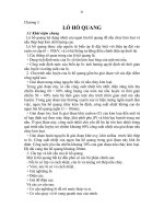
100×(1 – 298÷1000) ≈ 70 kJ, as illustrated in Figure 22a. Therefore, the quality of energy at
1000 K is 70%. The entropy change of the hot gases is –0.1 kJ K
–1
(= –100 ÷ 1000), while the
entropy gain for the ambient is 0.1 kJ K
–1
(i.e., 30 kJ÷300 K).
Alternatively, we can cool the hot gases using water to transfer the 100 kJ of energy.
Assume that during this process the water temperature rises by 2 K from 399 K to 401 K (with
the average water temperature being 400 K, as shown in Figure 22b). If a Carnot engine is
placed between the water at 400 K and the ambient at 300 K, then for the same 100 kJ of heat
removed from radiator water, we can extract only 100×(1 – 298÷400) ≈ 25 kJ, and 75 kJ is
rejected to the ambient. In this case, the energy quality is only 25% of the extracted heat.
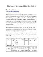
Figure 23 illustrates the processes depicted in Figure 22a and b using a T–S diagram. The cy-
cle A–B–C–D–A in Figure 23 represents the Carnot engine (CE) of Figure 22a, while area
ABJIA and EGKIE represent heat transfer from engine and to hot water, respectively, for
Figure 22b, while the area C–D–I–H represents the rejected heat of CE for the first case, and
the area D-C-H–K–J–I–D that for the latter case. Since more heat is rejected for the second
case, the work potential or the quality of the thermal energy is degraded to a smaller value at
the lower temperature. This is due to the irreversible heat transfer or the temperature gradients
between hot gases and radiator water (as shown in Figure 22b). In general property gradients
cause entropy generation.
Now, one might ask about the Maxwell-Boltzmann distribution of molecular veloci-
ties. Consider a monatomic gas within a container with rigid adiabatic walls. A “pseudo” tem-
perature distribution exists for the monatomic gas. The question is whether with collision and
transfer of energy, there can be degradation of energy or generation of entropy. First, tem-
perature is a continuum property and the temperature cannot be associated with a group of
molecules. Secondly, after frequent collisions, at that location where frequent transfers occur,
the intensive state is not altered over a time period much larger than collision time. Thus, no
gradient exists and there is no entropy generation.
a. Adiabatic Reversible Processes
Recall that for any process within a closed or fixed mass system, dS = δQ/T
b
+ δσ.
For any reversible process δσ =0 so that dS = δQ/T. For an adiabatic reversible process, δQ =
δσ = 0, so that
dS = 0.
Consequently, the entropy remains unchanged for an adiabatic reversible process. These
processes are also known as isentropic processes.
b
a
Figure 22: a. Carnot engine operating between hot gases and the ambient; b.
Carnot engine operating between water and the ambient.
E. ENTROPY EVALUATION
The magnitude of heat transfer can be determined through measurements or by ap-
plying the First law. Thereupon, in the context of Eq. (28), if the entropy change is known, δσ
may be determined for a process. The entropy is a property that depends upon the system state
and is evaluated at equilibrium.
Consider the irreversible process illustrated in Figure 24 involving the sudden com-
pression of a gas contained in a piston–cylinder assembly with a large weight. The dashed
curve in Figure 24 depicts the accompanying irreversible process. Applying the First law to the
process we obtain
Q
12
– W
12
= U
2
– U
1
.
The change in state due to an irreversible process can also be achieved through a se-
quence of quasiequilibrium processes as described by the path A in Figure 24. Applying the
First law to this path, we obtain the relation
Q
1
-
2R–2
– W
1–2R–2
= U
2
– U
1
.
Integrating Eq. (28) (with δσ= 0) along this path A ,
S
2
– S
1
= ∫
1
2
δQ
R
/T. (33)
since δσ = 0. The infinitesimal heat transfer δQ
R
along the path A is obtained from the First
law for a sequence of infinitesimal processes occurring along the reversible path 1–2R–2, i.e.,
δQ
R
= dU + δW
R
= dU + P dV.
Therefore, Eq. (33) may be written in the form
KI J
FE
CD
A B
G
H
Figure 23: T-s diagram for the processes indicated in the previous figure.
S
2
– S
1
= ∫(dU + PdV)/T. (34)
Integrating this relation between the initial and final equilibrium states
S
2
– S
1
=
TdU PTdU
U
U
V
V
−−
∫
+
∫
11
1
2
1
2
. (35)
The values of pressure and temperature along the path 1–2R–2 in Eq.(35) are different
from those along the dashed line 1–2, except at the initial (T
1
, P
1
) and final (T
2
, P
2
) states. If
the state change is infinitesimal
dS = (dU/T) + (P/T) dV, or (36)
TdS = dU + PdV, (37)
which is also known as the TdS relation. Equation (37) results from a combination of the First
and Second laws applied to closed systems.
S
V
U
S
2
S
1
Path B
Path A
2R
irrever
2R’
Figure 24: An irreversible process depicted on a U-V-S diagram. An illustration of estimating s by
reversible path.
Since the entropy is a property, the difference (S
2
– S
1
) as shown in Eq. (35) is a func-
tion of only the initial (U
1
,V
1
) and final (U
2
,V
2
) states, i.e., for a closed system S = S(U,V).
For example, if the initial and the final pressures and volumes are known, the temperature dif-
ference T
2
- T
1
can be determined using the ideal gas relation T
2
= P
2
V
2
/(mR) and T
1
= P
1
V
1
/(mR), even though the final state is reached irreversibly, i.e., the functional relation for T
2
-
T
1
is unaffected. Likewise, to determine the final functional form for the difference (S
2
–S
1
),
any reversible path A or B may be selected, since its value being path–independent depends
only upon the initial and final states. (This is also apparent from Eq. (36) from which it follows
that dS = 0 if dU = dV = 0.) For the processes being discussed, the internal energy change as-
sumes the form
dU = T dS – P dV. (38)
For an infinitesimal process, Eq. (38) represents the change of internal energy between two
equilibrium states with the properties U and U+ dU, S and S +dS, and V and V+dV.
Recall from Chapter 1 that the higher the energy, the greater the number of ways by
which molecules distribute energy. In confirmation, according to Eq.(36), as the internal en-
ergy increases in a fixed mass and volume system, the entropy too must increase. Therefore,
the entropy is a monatomic function of the internal energy for a given volume and mass. The
gradient of the entropy with respect to the internal energy is the inverse of the temperature T
–1
.
If the internal energy is fixed, Eq.(36) implies that as the volume increases, so does the entropy
(which confirms the microscopic overview outlined in Chapter 1). This is to be expected, since
more quantum states are available due to the increased intermolecular spacing.
Upon integrating Eq. (36), functional relation for the entropy is
S = S(U,V) + C, or U = U(S,V) + C. (39a and b)
0
0.2
0.4
0.6
0.8
1
1.2
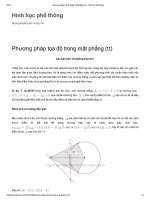
150 200 250 300
u, kJ/
k
s, kJ/kg K
R-1
2
v= 0.0022m
3
/k
g
0.0
3
0.1
2
Figure 25: Variation of s with u with v as a parameter.
The latter is also known as the Gibbs fundamental relation for systems of fixed mat-
ter. If the composition of a system is known, it is possible to evaluate the constant C which is a
function of the number of moles of the various species (N
1
, N
2
,…, etc.) or their masses (m
1
,
m
2
,…, etc.) that are contained in the closed system of fixed total mass m. If the composition of
the system is fixed, i.e., if the number of species moles N
1
, N
2
,…, etc. are fixed, then S =
S(U,V) which is also known as the fundamental equation in entropy form.
On a unit mass basis Eq. (36) may be written in the form
ds = du/T + Pdv/T, (40)
so that for a closed system of fixed mass
s = s (u,v). (41)
Figure 25 contains an experimentally–determined relationship between s and u with v as a pa-
rameter for the refrigerant R–12.
Since dU = dH – d (PV), Eq. (36) assumes the form
dS = dH/T – VdP/T. (42)
It is apparent from Eq. (42) that S = S(H,P). Writing Eq.(42) on unit mass basis
ds = dh/T – v dP/T, i.e., (43)
s = s(h,P). (44)
Note that only for exact differentials or differentials of properties can one give the
functional relation like Eq. (44). On the other hand consider the example of electrical work
supplied to a piston–cylinder–weight assembly resulting in gas expansion. In that case. the
work
δW = P dV –E
elec
δq
c
, (45)
where δq
c
denotes the electrical charge and E
elec
the voltage. It is not possible to express W =
W(V,q
c
), since δW is an inexact differential (so that W is not a point function).
1. Ideal Gases
Substituting for the enthalpy dh = c
p0
(T) dT, Eq. (43) may be written in the form
ds = c
po
dT/T – R dP/P. (46)
a. Constant Specific Heats
Integrating Eq. (46) from (T
ref
,P
ref
) to (T,P)
s(T,P) – s(T
ref
,P
ref
) = c
po
ln(T/T
ref
) – R ln(P/P
ref
). (47a)
Selecting P
ref
= 1 atmosphere and letting s(T
ref
,1) = 0, we have
s(T,P) = c
p0
ln (T/T
ref
) – R ln (P(atm)/1(atm)). (47b)
Selecting an arbitrary value for T
ref
, and applying Eq. (47b) at states 1 and 2,
s(T
2
,P
2
) – s(T
1
,P
1
) = c
po
ln(T
2
/T
1
) – R ln(P
2
/P
1
). (47c)
For an isentropic process s
2
= s
1
. Consequently,
c
po
ln(T
2
/T
1
) = R ln(P
2
/P
1
). (47d)
Since R = c
po
– c
vo
, applying Eq. (47d)
T
2
/T
1
= (P
2
/P
1
)
k/(k-1)
, or P
2
/P
1
= (T
2
/T
1
)
(k-1)/k
, (47e and f)
where k = c
p0
/c
v0
. Finally, upon substituting for T = Pv/R in Eq. (47e), we obtain the relation
Pv
k
= Constant. (47g)
b. Variable Specific Heats
Consider an ideal gas that changes state from (T
ref
,P
ref
) to (T,P). Integrating Eq. (46)
and setting s(T
ref
,P
ref
) = 0 we have
s(T,P) =
(c (T) / T)
p0
T
T
ref
dT
∫
– R ln (P/P
ref
).
For ideal gases, the first term on the right is a function of temperature alone. Setting P
ref
= 1
atm, the entropy
s(T,P) = s
0
(T) – R ln (P(atm)/1(atm)), where (48a)
s
0
(T) =
(c (T) / T)
p0
T
T
ref
dT
∫
. (48b)
If data for the specific heat c
p0
(T) are available (Tables A-6F), Eq. (48b) can be read-
ily integrated. In general, tables listing s
0
(T) assume that T
ref
= 0 K(Tables A-7 to A-19). There-
fore,
s(T,P) = s
0
(T) – R ln (P/1), (49)
where the pressure is expressed in units of atm or bars. If P = 1 atm or approximately bar, s(T,
1) = s
o
(T) which is the entropy of an ideal gas at a pressure of 1 bar and a temperature T. The
second term on the RHS of Eq. (49) is a pressure correction. Applying Eq. (49) to states 1 and
2,
s(T
2
,P
2
) – s(T
1
, P
1
) =s
0
(T
2
) –s
0
(T
1
) – R ln (P
2
/P
1
). (50a)
For an isentropic process
s
0
(T
2
) –s
0
(T
1
) – R ln (P
2
/P
1
) = 0. (50b)
Therefore, for an isentropic process, if the initial and final pressures, and T
1
are specified,
s
0
(T
2
) can be evaluated. Using the appropriate tables for s
0
(T) (e.g.: Tables A-7 to A-19), T
2
may be determined.
For processes for which the volume change ratios are known, it is useful to replace
the pressure term in Eq. (50b) using ideal gas law:
s
0
(T
2
) –s
0
(T
1
) – R ln ((RT
2
/v
2
)/(RT
1
/v
1
)) = 0.
Simplifying this relation,
s
0
(T
2
) –s
0
(T
1
) – R ln (T
2
/T
1
) + R ln (v
2
/v
1
) = 0. (50c)
For a known volume ratio and temperature T
1
, Eq. (50c) may be used to solve for T
2
itera-
tively. In order to avoid the iterative procedure, relative pressures and volumes, P
r
and v
r
, may
be defined using Eq. (50b) as follows (further details are contained in the Appendix to this
chapter)
P
r
(T)= exp(s
0
(T)/R)/exp (s
0
(T
ref
´)/R), and (50d)
v
r
= (T /exp (s
0
(T)/R))/(T
ref
´/exp(s
0
(T
ref
´)/R)), (50e)
where T
ref
´ is an arbitrarily defined reference temperature. For air, T
ref
´ is taken to be 273 K,
and
P
r
= 0.00368 exp(s
0
(T)/R)
Equations (50b) and (50c) can also be written in the form
P
2
/P
1
=P
r2
/P
r1
, and (50f)
v
2
/v
1
= v
r2
/v
r1
. (50g)
The value of v
r
in SI units is based on the relation
v
r
= 2.87 T/P
r
Tabulations for P
r
and v
r
particularly for solution of isentropic problems were necessary in the
past due to the nonavailability of computers. Since their advent, the system properties at the
end of isentropic compression or expansion are readily calculated.
The isentropic and nonisentropic processes can now be explained as follows. Con-
sider a monatomic gas. When an adiabatic reversible compression process occurs in a closed
system the work input is converted into a translational energy increase (e.g., due to increased
molecular velocity (V
x
2
+ V
y
2
+ V
z
2
) because of a force being applied in a specific direction,
say “x” which increases V
x
). Thus, the total number of macro-states cannot change. A crude
way to interpret is that dS = dU/T + P dV/T so that S generally increases with increased energy
U but decreases due to a decrease in volume V. The entropy first increases due to increased U
because of work input (the first term on the RHS) but decreases due to the reduced volume (as
the second term, due to the intermolecular spacing, is reduced and, consequently, the number
of states in which energy can be stored also decreases). The second term counteracts the en-
tropy rise due to the increased internal energy, and the entropy is unchanged.
l. Example 12
Air is adiabatically and reversibly compressed from P
1
= 1 bar, and T
1
= 300 K to P
2
= 10 bar. Heat is then added at constant volume from a reservoir at 1000 K (T
R
) until
the air temperature reaches 900 K (T
3
). During heat addition, about 10% of the added
heat is lost to the ambient at 298 K. Determine:
The entropy generated σ
12
in kJ kg
–1
K
–1
for the first process 1–2;
The net heat added to the matter;
The heat supplied by the reservoir;
The entropy generated in an isolated system during the process from (2) to (3).
Solution
S
2
– S
1
– ∫δQ/T
b
= σ
12
.(A)
Since the process is reversible,
σ
12
= 0, (B)
which implies that no gradients exist within the system. Therefore,
T
b
= T. (C)
Using Eqs. (A), (B), and (C)
S
2
– S
1
= ∫δQ/T. (D)
Since the process is adiabatic δQ = 0, and S
2
= S
1
or s
2
= s
1
. At state 1, from the air
tables (Tables A-7), p
r1
= 1.386, u
1
= 214.07, and h
1
= 300.19. Therefore,
s
1
= s
0
(T
1
) – R ln P/1 = 1.702 – 0 = 1.702 kJ kg
–1
K
–1
.
For the isentropic process
p
r2
(T
2
)/ p
r1
(T
1
) = p
2
/p
1
= 10. Hence, p
r2
= p
r1
10 = 1.386×10 = 13.86 so that
T
2
= 574 K, u
2
= 415 kJ kg
–1
, h
2
= 580 kJ kg
–1
, and s
2
= s
1
= 1.702 kJ kg
–1
K
–1
.
Temperature gradients can develop inside a system during heat addition from a ther-
mal reservoir or heat loss to the ambient, thereby making a process internally irre-
versible. In this example, the final states are assumed to be at equilibrium. Applying
the First law to the constant volume process, the heat added to the system can be
evaluated as follows
q
23
= u
3
– u
2
= 674.58 – 415 = 260 kJ kg
–1
.
If q
R
denotes the heat supplied by reservoir, the heat added q
23
= 0.9 q
R
, i.e.
q
R
= 288.88 kJ kg
–1
.
The heat loss to the ambient is q
0
= 288.88 – 260 = 28.88 kJ kg
–1
.
Since we must determine the entropy of an isolated system, assuming that there are no
gradients outside that system, and selecting the system boundaries to include the res-
ervoir at T
R
and the ambient at T
0
, it follows that
s
3
– s
2
– q
R
/T
R
– q
0
/T
0
= σ.
Now, P
3
/P
2
= T
3
/T
2
= 900÷574 , i.e., P
3
= 15.68 atm, and s
3
= 2.849 – 0.287 ln
(15.68÷1) = 2.059 kJ kg
–1
K
–1
. Therefore,
2.059 – 1.702 – (289/1000) – (–29/298) = σ so that
σ = 0.165 kJ kg
–1
K
–1
.
Remarks
It is possible to tabulate p
r
values for a particular gas using Eq. (50c).
2. Incompressible Liquids
For incompressible liquids and solids, the specific volume v is constant. Since u =
u(T,v), for incompressible substances it follows that u = u(T). The intermolecular spacing in
incompressible liquids is constant and, consequently, the intermolecular potential energy is
fixed so that the internal energy varies only as a function of temperature. Since, h = u + Pv, for
incompressible liquids
h(T,P) = u(T) + P v.
Differentiating with respect to the temperature at fixed pressure,
c
P
= (∂h/∂T)
P
= (∂u/∂T)
P
.
Since u = u(T), it follows that
c
P
= (∂u/∂T)
P
= du/dT = c
v
= c,
and for incompressible substances
du = cdT. (51)
The values of c for liquids and solids are tabulated in Tables A-6A and A-6B. Using Eq. (40),
ds = du/T + 0, so that
ds = cdT/T. (52)
Therefore, the entropy is a function of temperature alone. For any substance s = s(T,v) so that
if v = constant, s = s(T). Note that Eq. (43) cannot be used since h = h(T,P). Equations (51)
and (52) are applied to evaluate the internal energy and entropy of compressed liquids.
For example, water at 25ºC and 1 bar exists as compressed liquid, since P >
P
sat
(25ºC). The Steam tables (Tables A-4A) tabulate values of u(T) and s(T) as a function of
temperature for saturated water. If the entropy of liquid water is desired at 25ºC and 1 bar,
since u(T,P) ≈ u(T,P
sat
) = u
f
(T), and s(T,P) ≈ s(T,P
sat
) = s
f
(T), the respective tabulated values
are 104.9 kJ kg
–1
K
–1
and 0.367 kJ kg
–1
K
–1
. Likewise, the enthalpy at that state is
h = u + P v = 104.9 + 1×100×0.001 = 105 kJ kg
–1
.
An incompressible substance with constant specific heat is also called a perfect in-
compressible substance. For these substances, integration of Eq. (52) between T and reference
temperature T
ref
yields
s – s
ref
= c ln(T/T
ref
), (53a)
or between two given states
s
2
– s
1
= c ln(T
2
/T
1
). (53b)
When an incompressible liquid undergoes an isentropic process, it follows from Eq. (53b) that
the process is isothermal.
3. Solids
Equation (53), which presumes constant specific heat, is also the relevant entropy
equation for incompressible solids. However as T→0, Eq. (53) becomes implausible, forcing
us to account for the variation of the specific heat of solids at very low temperatures. At these
temperatures
c
v
(T) = 3 R(1 – (1/20)(θ
D
/T)
2
), where T » (θ
D
= 3 R (4 π
4
/5) (T/θ
D
)
3
), (54)
where θ
D
is known as the Debye temperature. A solid that behaves according to Eq. (54) is
called a Debye solid.
Another pertinent relation is the Dulong–Petit law that states that
c
v
≈ 3 R.
This is based on the presumption that a mole of a substance contains N
avag
independent oscil-
lators vibrating in three directions, with each molecule contributing an amount (3/2)k
B
T to the
energy. Molecules contribute an equal amount of potential energy, i.e., (3/2)k
B
T. At low tem-
peratures, the Dulong–Petit constant specific heat expression leads to erroneous results, and a
correction is made using the Einstein function E(T
Ein
/T), i.e.,
c
v
≈ 3 R E(T
Ein
/T), where
E(T
Ein
/T) = (T
Ein
/T)
2
exp(T
Ein
/T)/(exp(T
Ein
/T)–1)
2
.
Here, T
Ein
denotes the Einstein temperature. (For many solids, T
Ein
≈ 200 K.) As T→0,
E(T
Ein
/T)→T
2
. For coals,
c
v
≈ 3 R((1/3)E(T
Ein,1
/T) + (2/3) E (T
Ein,2
/T)),
where T
Ein,2
denotes the second Einstein temperature.
4. Entropy During Phase Change
Consider the case of a boiling liquid. Since the pressure and temperature are generally
unchanged during a phase transformation, applying Eq. (43),
ds = dh/T – vdP/T = dh/T. (55)
Integrating the expression between the saturated liquid and vapor states
s
g
– s
f
= (h
g
–h
f
)/T = h
fg
/T. (56)
Generalizing for any change from phase α to β,
s
α
– s
β
= h
αβ
/T (57)
m. Example 13
The entropy of water at T
tp
= 0ºC ,P
TP
= 0.611 kPa, is arbitrarily set to equal zero,
where the subscript tp refers to the triple point. Using this information, determine:
s(liquid, 100ºC) assuming c = 4.184 kJ kg
–1
K
–1
. Compare your results with values
tabulated in the Steam tables (Tables A-4).
s(sat vapor, 0ºC, 0.611 kPa) assuming h
fg
= 2501.3 kJ
–1
kg
–1
K
–1
.
The entropy generated if the water at 0ºC and 0.611 kPa is mechanically stirred to
form vapor at 0ºC in an adiabatic blender.
s(393 K, 100 kPa) assuming c
p,0
= 2.02 kJ kg
–1
K
–1
and that steam behaves as an ideal
gas.
Solution
Applying Eq. (53),
s(373) – s(273) = 4.184 ln (373/273) = 1.306 kJ kg
–1
K
–1
.
Since s(0ºC) = 0, s(100ºC) =1.306 kJ kg
–1
K
–1
.
From the Table A-4A, s(100ºC) = 1.3069 kJ kg
–1
K
–1
, which is very close.
Applying Eq. (56) to the vaporization process at the triple point,
s
g
– s
f
= 2501.3÷273 = 9.16 kJ kg
–1
K
–1
. Since,
s
f
(273 K, 0.611 kPa) = 0, s
g
(273 K, 0.611 kPa) = 9.16 kJ kg
–1
K
–1
.(A)
ds – δq/T
b
= δσ. Since δq = 0, ds = δσ. Integrating this expression,
s
g
– s
f
= σ. (B)
Using Eq. (A) and (49b), with s
f
(0ºC, 0.611 kPa) = 0
s
g
– s
f
= 9.16 kJ kg
–1
K
–1
= σ. (C)
s(393 K, 100 kPa) – s(273 K, 0.611) =
2.02 ln (393÷273) – (8.314÷18.02)ln (100÷0.611) = – 1.616 kJ kg
–1
K
–1
, or
s(393, 100 kPa) = 9.16 – 1.616 = 7.54 kJ kg
–1
K
–1
.
Conventional Steam tables (e.g., Table A-4A) yield a value of 7.467 kJ kg
–1
K
–1
.
Figure 26: P–v diagram for water.
Remarks
For estimating entropy in vapor phase at low pressures, one can use ideal gas tables
(Tables A-12) also, e.g., s(393,100) – s (273,0.611)= (s
0
(393) – R ln (100/100)) – (s
0
(273) – R ln (0.611/100)) where P
ref
= 100 kPa
The stirring process is irreversible. Therefore, viscous dissipation converts mechani-
cal energy into thermal energy. The heat vaporizes the liquid, and increases the en-
tropy.
n. Example 14
Determine the enthalpy of water at 25ºC and 1 bar (i.e., at point A of Figure 26) if the
enthalpy of saturated liquid (at point F) at that temperature is known.
Solution
From the Steam tables (A-4A) P
sat
= 0.03169 bar and h
f
= 104.89 kJ kg
–1
for saturated
liquid water at 25ºC (at point F). Since c = constant for incompressible liquids,
ds = c dT/T (A)
Along the 25ºC isotherm (curve FA), Eq. (A) illustrates that ds = 0, and the process is
isentropic. Since, dh = Tds + vdP, for this case
dh = v dP.
T
A
C
S
G
D
h=Const
h=Const
P=Const
u=Const
Pc
B
F
S
v=v
C
Figure 27: T-s diagram of a pure fluid.
Upon integrating
between points F and
A,
h
A
(25 C, 1
bar) – h
F
(25ºC,
0.03169 bar)
= ∫v dP ≈ v
f
(25ºC,
0.03169) (P
A
– P
F
)
=
1.0029×10
–3
× (100 – 3.169) = 0.09711 kJ kg
–1
, and
h
A
(25 C, 1 bar) = 104.89 + 00.09711= 104.987 kJ kg
–1
.
Remarks
Since the enthalpy values are virtually insensitive to pressure, one can assume that h
A
≈ h
F
, i.e., the enthalpy of a compressed liquid at given temperature and pressure is ap-
proximately that of the saturated liquid at that temperature.
If pressure at point A is 25 bar, h
A
= 104.89 + 2.504 = 107.394 kJ kg
–1
. Use of Table
A-4 yields a value of 107.2 kJ kg
–1
, which is very close, with the difference being due
to the assumption of constant specific volume.
a. T–s Diagram
We are now in a position to discuss the representation of the states of a pure fluid on a
T–s diagram. For instance, we may arbitrarily assign a zero entropy to liquid water at its triple
point (i.e., point B of Figure 27). For incompressible liquids, we can assume that s(0.01ºC, 1
bar) ≈ s(0.01ºC,0.006 bar) = 0. If the water is again heated from 0.01ºC to 100 C at 1 bar, it is
possible to evaluate the values of s, and those of s
f
(100ºC, 1 bar), (point F) using Eq. (53), and
s
g
(100ºC, 1 bar) (point G) using Eq. (56). If the vapor behaves as an ideal gas (which is gener-
ally true at lower pressures) the entropy may be evaluated using either of Eqs. (47c) or (50a)
(Point S) . In this manner, the behavior of a substance can be characterized at lower pressures
on the T–s diagram, as illustrated by the curve BFGS in Figure 27 at 1 bar. Thereafter, by
changing the pressure, entropy values can be obtained at higher pressures. Since the ideal gas
assumption is flawed at elevated pressures, Eqs. (47c) or (49) must be modified. This will be
discussed further in Chapters 6 and 7. As is apparent from the path A–C–D, an inflection oc-
curs in the slope of the isobar (at the critical pressure P
c
) at the critical point C, i.e., (∂T/∂s)
Pc
=
0 at this point. Also illustrated on the diagram are isometric, isenthalpic and isoquality lines.
5. Entropy of a Mixture of Ideal Gases
a. Gibbs–Dalton´s law
The application of the Gibbs–Dalton law to characterize a multicomponent gaseous
mixture is illustrated in Figure 28. Two components species are hypothetically separated, and
the component pressures P
1
and P
2
are obtained. Thereby, the component pressure P
k
is deter-
mined as though component k alone occupies the entire volume (i.e., no other components are
present) at the mixture temperature. Thereafter, using the component pressures, the entropy is
evaluated, i.e.,
S (T,P, N) = ΣS
k
(T,p
k
,N
k
) =N
k
s
k
(T, p
k
). (58)
For ideal gases, the component pressure for a species is identical to its partial pressure, namely,
p
k
´ = X
k
P = p
k
, (59)
, P , P
1
, P
1
Figure 28: Illustration of the Gibbs-Dalton law.
where p
k
´ denotes the partial pressure of species k in the mixture. For ideal gases p
k
´ = p
k
.
This subject is discussed in greater detail in Chapter 8 on mixtures.
b. Reversible Path Method
A general method to determine the mixture entropy using the relation dS = δQ
rev
/T is
derived in the Appendix.
o. Example 15
A piston–cylinder assembly contains a 0.1 kmole mixture consisting of 40% CO
2
and
60% N
2
at 10 bars and 1000 K (state 1). The mixture is heated to 11 bars and 1200 K
(state 2). The work output from the assembly is 65.3 kJ. Evaluate the entropy change
S
2
–S
1
and σ
12
for the following cases:
The boundary temperature T
b
equals that of the gas mixture.
T
b
is fixed and equals 1300 K during heat up.
Solution
S =
Ns
k
k
Tp
k
(, )
∑
(A)
For the mixture
S =
N
CO
2
s
CO
2
(T,
P
CO
2
) +
N
N
2
s
N
2
(T,
P
N
2
), (B)
S
1
= (
N
CO
2
s
CO
2
(T,
P
CO
2
) +
N
N
2
s
N
2
(T,
P
N
2
))
1
, (C)
S
2
= (
N
CO
2
s
CO
2
(T,
P
CO
2
) +
N
N
2
s
N
2
(T,
P
N
2
))
2
,where (D)
N
CO
2
= 0.4 × 0.1 = 0.04 kmole, and
N
N
2
= 0.6×0.1 = 0.06 kmole.
Now,
s
CO
2
(T,P
k
) =
s
CO
2
0
(T) –
R
ln (
P
CO
2
/1), where
(
P
CO
2
)
1
= 0.4 × 10 = 4 bar, (
P
CO
2
)
2
= 0.4 × 11 = 4.4 bar, and
(
P
N
2
)
1
= 0.6 × 10 = 6 bar, (
P
N
2
)
2
= 0.6 ×11 = 6.6 bar.
Therefore, at conditions 1 and 2, respectively,
s
CO
2
(1200K, 4.4 bar) =
s
CO
2
0
(1200 K) –
R
ln(4.4÷1)
= 234.1 – 8.314 × ln(4.4÷1) = 221.8 kJ kmole
–1
K
–1
, and,
s
CO
2
(1000K, 4 bar) =
s
CO
2
0
(1000 K) –
R
ln(4÷1) = 216.6 kJ kmole
–1
K
–1
.
Likewise,
s
N
2
(1200K, 6.6 bar) =
s
N
2
0
(1200 K) –
R
ln(6.6÷1)
= 279.3 – 8.314 × ln (6.6÷1) = 263.6 kJ kmole
–1
K
–1
, and
s
N
2
(1000K, 6 bar) = 269.2 – 8.314 × ln 6 = 254.3 kJ kmole
–1
K
–1
.
Using Eqs. (C) and (D)
S
1
= 0.04 × 216.6 + 0.06 × 254.3 = 23.92 kJ K
–1
,
S
2
= 0.04 × 221.8 + 0.06 × 263.6 = 24.69 kJ K
–1
, and
S
2
– S
1
= 24.69 – 23.92 = 0.77 kJ K
–1
.
S
2
– S
1
– Q
12
/T
b
= σ
12
. (E)
Applying the First law, Q
12
= U
2
– U
1
+ W
12
. Therefore,
U
2
= 0.04 × 43871 + 0.06 × 26799 = 3362.8 kJ,
U
1
= 0.04 × 34455 + 0.06 × 21815 = 2687.1 kJ, and
Q
12
= 3362.8 – 2687.1 + 65.3 = 741 kJ.
Using these results in Eq. (E)
σ
12
= 0.77 – 741/1300 = 0.2 kJ K
–1
.
F. LOCAL AND GLOBAL EQUILIBRIUM
A system exists in a state of thermodynamic equilibrium if no changes occur within
the system in the absence of any interactions (of mass or energy). The entropy cannot be
evaluated for a system that contains internal temperature gradients. However, it is possible to
determine the entropy for a small elemental mass with the assumption of local equilibrium.
Summing the local entropy over all the elemental masses contained in a system, the system
entropy can be determined. However, the concept of intensive system entropy is meaningless
in this case.
p. Example 16
Consider a container of length 2L, width W, and height H that is filled with water.
Due to cooling, at a specified time t, the water temperature at the center of the con-
tainer is 320 K, while that adjacent to the walls is 300 K (cf. Figure 29). The initial
temperature profile follows the relation
T = T
max
– (T
max
– T
0
) x/L (A)
Assuming local equilibrium initially, obtain an expression for S
1
at time t.
The pool is now insulated and the entire pool is allowed to reach equilibrium. What
are the final system and specific entropies? Assume the water mass to equal 1000 kg.
What is the entropy generated for the above process?
310K
320
K
(1) Initial State
(2) Final State
Figure 29: Illustration of global and local equilibrium.
Solution
Assuming local equilibrium for an elemental mass dm = W H dx ρ,
S
1
= 2
x
xL
=
=
∫
0
(c ln (T/T
ref
)) (W H dx p). (B)
Employing Eqs. (A) and (B), with T
ref
= T
0
we have
S
1
/(2L W H ρ) = c(T
0
/(T
max
–T
0
))((T
max
/T
0
) ln(T
max
/T
0
)–T
max
/T
0
+1). (C)
S
1
/(2LWHP)=0.1365 kJ/kgk
Noting that 2LWHP is the pool mass of 1000 kg.
Therefore, S
1
= 136.5 kJ K
-1
.
Therefore, S
1
= 1159 kJ K
–1
.
At the final state S
2
/(2 L W H p) = c ln (T
2
/T
0
). Using values for c = 4.184 kJ kg
-1
K
-1
,
T
max
= 320 K, T
0
= 300 K, mass m = 2LWHP= 1000 kg, and using a linear tempera-
ture profile that yields T
2
= 400 K we have,
S
2
= 137.2 kJ K
-1
, and s
2
= 0.1372 kJ kg
-1
K
-1
.
Therefore, (S
2
- S
1
) =0.7 kJ K
-1
.
Although the internal energy, volume, and mass remain unchanged, the entropy
changes during the irreversible equilibration process.
Since the process is adiabatic, s = S
2
- S
1
= 0.7 kJ K
-1
.
Remarks
Assume that the universe was formed from a highly condensed energy state during a
big bang that resulted in temperature gradients (e.g., formed by the temperatures at
the surface of the sun and the earth). With this description the universe is currently in
the process of approaching an equilibrium state, and, consequently, its entropy is
continually increasing. Once the equilibrium state is reached no gradients will exist
within the universe, and the entropy will reach a maximum value.
G. SINGLE–COMPONENT INCOMPRESSIBLE FLUIDS
For incompressible fluids the internal energy and entropy may be written in the forms
u = c (T–T
ref
), and s = c ln(T/T
ref
). Manipulating the two relations
s = c ln ((u/c + T
ref
)/T
ref
), i.e., (60a)
s = s(u). This relation is called the entropy fundamental equation for an incompressible sin-
gle–component fluid. Likewise, expressing the internal energy as a function of the entropy,
u = c T
ref
(exp (s/c) – 1), i.e., (60b)
it follows that u = u(s). This relation is called the energy fundamental equation for an incom-
pressible single–component fluid. Similarly, the enthalpy fundamental equation may be ex-
pressed in the form
h = u + Pv
ref
= c T
ref
(exp(s/c) –1) + Pv
ref
= h (s,P).
This is discussed further in Chapter 7.
q. Example 17
Consider a vapor–liquid mixture in a closed system that is adiabatically and qua-
sistatically compressed. Is the process isentropic at low pressures? Assume that the
mixture quality does not change significantly (cf. Figure 30).
Solution
During the process the vapor is more readily compressed, which, in turn, compresses
the liquid droplets. If the process is to be isentropic, there should be no temperature
difference between the vapor and liquid drops. However isentropic compression of
incompressible drops cannot create a temperature rise, while it can do so for vapor.
Thus the vapor must heat the drops. Therefore, even though the process is quasistatic,
it is not a quasiequilibrium process, since internal temperature gradients exist during
compression, which cause irreversible heat transfer between the vapor and liquid
drops. Applying the First law,
–P (dV
v
+ dV
l
) = dU
v
+dU
l
,(A)
where the subscripts v and l, respectively, denote vapor and liquid. Upon compres-
sion, the increased vapor temperature causes the liquid drops to heat up, and it is
usual that the liquid temperature lags behind the vapor temperature. Finally, the sys-
tem equilibrates so that T
v,2
= T
2
= T
l,2
. In order to simplify the problem, we assume
that there is no vaporization during compression, i.e., first the vapor is compressed as
though the drops are insulated from it. Since the liquid has a specific volume of 0.001
m
3
kg
–1
while the vapor specific volume is of the order of 1 m
3
kg
–1
we can neglect
the small change in drop volume. Assuming ideal gas behavior for the vapor, we can
show using Eq. (A) (or assuming an isentropic process for the vapor) that
T
v,2
/T
v,1
= (V
1
/V
2
)
(k–1)
. (B)
Following compression the liquid and vapor reach the equilibrium temperature T
2
without any change in their respective volumes. Applying the First law,
m
v
c
v0
(T
v2
– T
2
) = m
l
c
l
(T
2
– T
1
). (C)
Solving for T
2
/T
1
T
2
/T
1
= (x c
v0
(T
v,2
/T
v,1
) + (1–x) c
l
)/(x c
v0
+ (1–x) c
l
) (D)
where x = m
v
/ (m
l
+ m
v
) denotes the mixture quality. Applying the entropy balance
equation S
2
– S
1
– ∫δQ/T
b
= σ,
s
2
– s
1
= σ/m = x (c
v0
ln (T
2
/T
1
+ R ln (V
2
/V
1
)) + (1–x) c
l
ln (T
2
/T
1
) (E)
(a)
(b)
Figure 30: Illustration of irreversibility during compression of two phase mixture.
Using values for the compression ratio V
1
/V
2
= 2, c
v0
= 1.5, c
l
= 4.184, and R = 0.46,
a plot of σ with respect to x with r
v
as a parameter can be generated (Figure 31).
When x = 1, the mixture is entirely vapor, and the process is reversible. When x = 0,
the mixture only contains liquid, and the process is again reversible. The entropy gen-
eration term σ reaches a maxima (which can be found by differentiating Eq. (E) with
respect to x, and, subsequently, setting dσ/dx = 0) in the vicinity of x = 0.6.
Remarks
We have ignored the influence of phase equilibrium and vaporization in the above
analysis. As the vapor is compressed, its temperature and pressure increase according
to the relation T
v,2
/T
1
= (P
2
/P
1
).
(k–1)/k
. Phase equilibrium effects induce the liquid tem-
perature T
sat
(P) to increase with the pressure according to a different relationship
compared to variation of vapor temperature during compression. If local phase equi-
librium near the drop surface is assumed during the compression process, invariably a
temperature difference exists causing irreversibility.
r. Example 18
Air (for which k = 1.4) is contained in an insulated piston–cylinder assembly under
the conditions P = 100 kPa, V = 0.1 m
3
and T = 300 K. The piston is locked with a
pin and its area is 0.010 m
2
. A weight of 2 KN is rolled onto the piston top and the pin
released.
Is the process reversible or irreversible?
Does the relation Pv
k
= constant, which is valid for an isentropic process, describe the
process?
Determine the final state.
Evaluate the entropy change s
2
– s
1
.
Solution
When the pin is released, the molecules adjacent to the piston are immediately com-
pressed making the local gas hotter while those farther away are not. Therefore, the
pressure near the piston top is higher than the cylinder bottom. This effect continues
as the piston moves inward, and the system is not at a uniform state. Thus a pressure
and temperature gradients are established. The process is irreversible.
0
0.02
0.04
0.06
0.08
0.1
0.12
0.14
0 0.1 0.2 0.3 0.4 0.5 0.6 0.7 0.8 0.9 1
Quality,
x
Ent.Gen., kJ/kg K
Compression Ratio
=
6
4
2
Figure 31: Entropy generated with respect to quality.
The relation Pv
k
= constant does not
apply, since the process is not isen-
tropic.
Using the method of Example 9 of
Chapter 2, P
2
= 2/0.010 = 200 kPa,
T
2
= 386 K, and V
2
= 0.065 m
3
.
Therefore,
s
2
–s
1
= c
p0
ln (T
2
/T
1
)–R
ln(P
2
/P
1
) = ln (386÷300)–0.286
ln(200÷100)
= 0.0538 kJ kg
–1
K
–1
.
s. Example 19
Consider an idealized air condition-
ing cycle used for storage tank ap-
plications. The objective is to cool
the water stored in a tank from 25ºC
(T
t,1
) to make ice at 0ºC (T
t,2
) by circulating cold Freon inside the tank. The ambient
temperature is 25ºC (T
0
). Determine the minimum work required for every kg of wa-
ter contained in the storage tank. The heat of fusion for water
sf sf
h
u
≈
()
is 335 kJ
kg
–1
(cf. Figure 32).
Solution
This example is similar to that contained in Example 7. We assume a Carnot refrig-
eration cycle discarding heat to a variable low temperature reservoir. The cycle oper-
ates at a fixed higher temperature T
0
. First, the water is cooled from the initial state
(state 1) to the melting point (MP) of ice, and then frozen at that temperature (state 2).
As shown in Example 7,
W
min
= – (U
t,2
– U
t,1
) + T
0
(S
t,2
– S
t,1
),
W
min
= – (mc(T
2
– T
1
) – m u
sf
) + T
0
(mc ln (T
2
/T
1
) – m u
sf
/T
freeze
), or
w
min
= W
min
/m = – (4.184×(0–25)–335)+298×(4.184×ln(273÷298)–335÷273)
= 439.6 – 298 × 1.594 = –35.41 kJ kg
–1
.
Remarks
Figure 32 contains a representation of the process on a T–s diagram. The area under
the path in the figure represents the reversible heat absorbed from the tank. We have
assumed that the low temperature (of Freon) during the refrigeration cycle is exactly
equal to the storage tank temperature. However, in practice it is not possible to trans-
fer heat in the absence of a temperature gradient without inducing some irreversibility
between the Freon and water contained in the tank.
t. Example 20
0.5 kg of coffee is contained in a cup at a temperature of 370 K. The cup is kept in an
insulated room containing air at a temperature of 300 K so that, after some time, it
cools to 360 K. The air mass is 100 kg. Assume the properties of coffee to be the
same as those of water, and determine the following:
The change in internal energy dU (= dU
coffee
+ dU
air
).
The initial entropy of the coffee and air if it is assumed that both subsystems exist at
an equilibrium state.
The heat transfer across the cup boundary δQ.
The temperature change of the air.
The entropy change of coffee dS
coffee
.
The entropy change of air dS
air
.
The entropy generated.
Figure 32: T-s diagram illustrating water in a
storage tank.
Solution
Consider an isolated composite system consisting of two subsystems, i.e., coffee and
air. In the absence of external interactions, isolated systems attain a stable equilibrium
state. The internal energy change dU = 0 by applying the First law for a combined
system, i.e.,
dU
coffee
= – dU
air
.(A)
S
coffee
= m s = 0.5 × s
f,370 K
= 0.5 × 1.25 = 0.625 kJ K
–1
. (B)
S
air
= 100 × s
300 K
= 100 × 1.7 = 170 kJ K
–1
. (C)
Therefore,
S = 170.625 kJ K
–1
. (D)
For the coffee δQ – δW = dU
coffee
= m c dT
coffee
= 0.5 × 4.184 × (–10) = – 20.92 kJ.
Since there is no volume change, δW = 0, and
δQ = – 20.92 kJ. (E)
Applying the First law dU
coffee
= – dU
air
(see Eq. (A)), since dU
coffee
= – 20.92 = –
dU
air
= – 100 × 1.0 × dT
air
,
dT
air
= 0.21 K. (F)
The air temperature does not rise significantly.
Assuming the coffee temperature to be uniform within the cup, we will select the
system so as to exclude boundaries where temperature gradients exist. Using the en-
tropy balance equation for closed systems, and for internally reversible processes,
dS
coffee
= δQ/T = – 20.92÷((360 + 370) × 0.5) = – 0.0573 kJ K
–1
. (G)
Employing Eq. (B),
S
coffee
= 0.625 – 0.0573 = 0.5677 kJ K
–1
.
dS
air
= 20.92÷((300 + 300.21) × 0.5) = + 0.0697 kJ K
–1
, and
S
air
= 170.0697 kJ K
–1
.
Forming a combined system that includes both coffee and air, δQ = 0. Applying the
entropy balance equation dS – 0 = δσ,
dS = dS
coffee
+ dS
air
= 0.0573 + 0.0697 = 0.0124 kJ K
–1
so that
δσ = 0.0124 kJ K
–1
.
You will also find that δσ → 0 when the coffee temperature almost equals that of the
air.
Remarks
In this case, δσ > 0 during the irreversible process in the isolated system.
δσ → 0 when the coffee temperature almost equals the air temperature (or as reversi-
bility is approached).
Vaporization of water into the air has been neglected.
u. Example 21
A gas undergoes an expansion in a constant diameter horizontal adiabatic duct. As the
pressure decreases, the temperature can change and the velocity increases, since the
gas density decreases. What is the maximum possible velocity?
Solution
From mass conservation
d(V/v) = 0, (A)
where V denotes velocity. Therefore, dV/v + V d(1/v) = 0. Applying energy conser-
vation
d(h + V
2
/2) = 0, and (B)
utilizing the entropy equation
dh = T ds + v dP, or ds = dh/T – v dP/T. (C)
Using Eqs. (A) and (B),
dh = – V dV = – V
2
dv/v. (D)
From Eqs. (D) and (C),
ds = – V
2
dv/(T v) – v dP/T. (E)
For an adiabatic duct, ds = δσ. Since δσ ≥0 for an irreversible process,
ds ≥0. (F)
Using Eqs. (F) and (E), V
2
≤ – v
2
(∂P/∂v)
s
. Typically (∂P/∂v)
s
< 0. Hence V
2
> 0. For
a reversible (i.e., isentropic) process,
V
2
= – v
2
(∂P/∂v)
s
(G)
which is the velocity of sound in the gas.
Remarks
In Chapter 7, we will discuss use of the enclosed software to determine the sound
speed in pure fluids.
H. THIRD LAW
The Third law states that a crystalline solid substance at an absolute temperature of
zero (i.e., 0 K) possesses zero entropy. This implies that the substance exists in a state of per-
fect order at that temperature in the absence of energy, a condition that is not particularly use-
ful, since it is no longer possible to extract work from it. In other words, the entropy of any
crystalline matter tends to zero as ∂U/∂S → 0. We will see in Chapter 7 that s(0 K) is inde-
pendent of pressure, i.e., s(0 K, P =1 bar) = s(0 K, P). Entropy values are tabulated for most
substances using the datum s = 0 at 0 K.
In general, substances at low temperatures exist in the condensed state so that for an
incompressible substance
ds = c
s
dT/T.
At very low temperatures the specific heat–temperature relation for a solid, c
s
= αT
m
can be
applied, so that
(s – s
ref
(0)) = αT
m
/m, m ≠ 0 (61a)
For Debye solids m = 3, and
α = (1944/θ
D
3
) kJ kmole
–1
K
–4
, at T < 15 K, (61b)
where θ
D
is a constant dependent upon the solid.
In summary, according to the Third law s = s
ref
(0) = 0 at an absolute temperature of
zero.
v. Example 22
The specific heat of a Debye solid (for temperatures less than 15 K) is represented by
the relation
c
s
= (1944 T
3
/θ
3
) kJ kmole
–1
K
–1
. Obtain a relation for the entropy with
respect to temperature for cyclopropane C
3
H
6
for which θ = 130. What are the values
of the entropy and internal energy at 15 K. (cf. also Figure 33).
Solution
The molar specific entropy (0 K, 1 bar) = 0 kJ kmole
–1
K
–1
(i.e., point A in Figure
33a). Since
s c dT T
s
=
∫
/
,
s
= (1944 T
3
/θ
3
)/3 kJ kmole
–1
K
–4
.
At 15 K,
s
(15 K, 1 bar) = (1944 × 15
3
/130
3
)/ 3 = 0.995 kJ kmole
–1
K
–1
.
The internal energy
u
= ∫
c
s
dT so that at
15 K,
u
= (1944 × 15
4
÷ 130
3
) ÷ 4 =
11.2 kJ kmole
–1
.
w. Example 23
c
l
= 76.5 kJ kmole
–1
K
–1
, and
h
fg
= 20,058 kJ
kmole
–1
.
Solution
From Example 22,
s
(s, 15 K) = 0.99 kJ kmole
–1
K
–1
(at point B in Figure 33). Hence,
s
(s, 145.5) –
s
(s,15) = 28.97 ln (145÷15) (i.e., point C, saturated solid in Figure 33a
and b which represents a saturated solid that is ready to melt). Therefore,
s
(s, 145.5) = 65.72 + 0.99 = 66.71 kJ kmole
–1
K
–1
, and
u
(s, 145.5) = 28.97 × (145 – 15) + 11.2 = 377.7 kJ kmole
–1
.
The liquid entropy may be evaluated as follows:
s
(l, 145.5) – s(s,145.5) = 5442÷145.5 = 37.40 kJ kmole
–1
K
–1
.
Therefore,
s
(l, 145.5) = 37.4 + 66.71 = 104.11 kJ kmole
–1
K
–1
(point D in Figure 33) so that
Figure 33: Illustration of a: a: P–T diagram; b. s–T diagram.
At a pressure of 1 bar,
evaluate the entropy
and internal energy of
cyclopropane C
3
H
6
when it exists as (a)
saturated solid; (b)
saturated liquid; and
(c) saturated vapor
given that the specific
heat c
s
follows the
Debye equation with
θ
D
= 130 K and m = 3
when T < 15 K,
c
s
=
28.97 kJ kmole
–1
K
–1
for 15 K < T < T
MP
,
where the melting
point T
MP
= 145.5 K at P = 1 bar, h
sf
= 5442 kJ k mole
-1
, and the normal boiling point
T
BP
= 240.3 K; and for the liquid
s
(l,240.3) – s(l,145.5) = 76.5 ln(240.3÷145.5) = 38.4 kJ kmole
–1
K
–1
, and
s
(l,240.3) = 38.4 + 104.11 = 142.51 kJ kmole
–1
K
–1
(point F in Figure 33).
Since h = u + Pv, and for solids and liquids Pv « u, it follows that for these substances
h ≈ u or h
sf
≈ u
sf
and h
fg
≈ u
fg
. Hence,
u(l,145.5) = 377.7 + 5442 =5819.9 kJ kmole
–1
, and
u(l,240.3) = 5819.9 + 76.5 × (240.3 – 145.5) = 13132 kJ kmole
–1
.
In the gaseous state
s
(g, 240.3) –
s
(l,240.3) = 20,058÷240.3 = 83.5 kJ kmole
–1
K
–1
, i.e.,
s
(g,240.3) = 83.5 + 142.51 = 226.01 kJ kmole
–1
K
–1
(point G in Figure 33).
Therefore,
s
(g,240.3) = 226 kJ kmole
–1
K
–1
, and
h(g, 240.3) = 13132 + 20.058 = 33,190 kJ kmole
–1
.
u(g, 240.3) = 33,190 - 8.314 × 240.3 = 31,192 kJ kmole
–1
.
Remarks
If the reference condition for the entropy is selected at the saturated liquid state (i.e.,
at point D), we can arbitrarily set s = 0 there. Therefore, at point C, saturated solid,
s
C
= –37.40 kJ kmole
–1
K
–1
, and at point B,
s
B
= –37.40 – 65.72 = –103.12 kJ kmole
–1
K
–1
. Such a procedure is generally used for water, since the reference condition with
respect to its entropy is based on the saturated liquid state at its triple point tempera-
ture of 0.01ºC. At this state it is usual to set s = h ≈ u = 0. Methods for evaluating at
any pressure and temperature will be discussed in Chapter 7.
Recall from the First law that δQ - δW =dU. Therefore, if a process involves irre-
versibility, then dS = δQ/T
b
+ δσ so that
dS = dU/T
b
+ δW/ T
b
+ δσ.
In case the process is mechanically reversible, then the entropy balance equation for a closed
system can also be written as
dS = dU/ T
b
+ P dV/ T
b
+ δσ.
where δσ >0 for irreversible processes and equals zero for reversible processes.
I. ENTROPY BALANCE EQUATION FOR AN OPEN SYSTEM
We have presented the entropy balance equation Eq. (28) for a closed system and
obtained relations describing the entropy of a fixed mass. We will now formulate the entropy
balance for an open system in an Eulerian reference frame.
1. General Expression
The entropy balance equation for a closed system containing a fixed control mass
assumes the form
dS
c.m.
– δQ/T
b
= σ
c.m.
, (28)
where the subscript c.m. denotes the control mass. Work does not explicitly enter into this ex-
pression. For an open system which exchanges mass, heat and work with its ambient (cf.
Figure 34), the derivation of the corresponding balance equation is similar to that of the energy
conservation equation. The entropy change within a fixed mass over an infinitesimal time δt
can be written in the form
dS
c.m.
= S
c.m.,t+dt
– S
c.m.,t
. (62a)
The control mass at time t (illustrated within the dashed boundary in Fig. 25(a)) includes both
the control volume mass and a small mass dm
i
waiting to enter the control volume. After an
infinitesimal time δt as the mass dm
i
enters at the inlet, a small mass dm
e
leaves through the
control volume exit, and for the control volume Eq. (62a) may be expressed in the form
dS
c.m.
= (S
c.v.,t+dt
+ dm
e
s
e
) – (S
c.v.,t
+ dm
i
s
i
). (62b)
Heat transfer can occur across the control volume boundary. In general, the boundary
temperature at its inlet (but within the dashed boundary) is different from the corresponding
temperature at the exit, and the heat transfer rate δQ may vary from the inlet to exit. For the
same of analysis we divide the boundary into sections such that at any section j the boundary
temperature is T
b,j
and the heat transfer rate across the boundary is
˙
Q
j
. For an infinitesimally
small time period δt, the term δQ/T is given as
(δQ/T
b
) = Σ
j
˙
Q
j
δt/T
b,j
. (63)
Using Eqs. (28), (62), and (63), expanding S
c.v.,t+
δ
t
in a Taylor series around time t, and divid-
ing the resultant expression by δt, and letting when δt → 0 so that the control mass and control
volume boundaries merge (i.e., c.m. → c.v
.
)
, we obtain
dS
c.v.
/dt =
˙
m
i
s
i
–
˙
m
e
s
e
+ Σ
j
˙
Q
j
/T
b,j
+
˙
σ
cv
. (64)
δδ
δδ
W
c.m. boundary
c.v. boundary
δδ
δδ
W
δδ
δδ
Q
1
δδ
δδ
Q
2
T
b,2
T
b,1
T
b,2
T
b,3
T
3
S
cv
dm
e,
s
e
dm
i,
s
i
Figure 34: Schematic diagram to illustrate the entropy balance equation.
On a mole basis Eq. (64) may be written in the form
dS
c.v.
/dt =
˙
Ns
ii
–
˙
Ns
ee
+ Σ
j
˙
Q
j
/T
b,j
+
˙
σ
cv
, (65)
and generalizing for multiple inlets and exits
dS
c.v.
/dt = Σ
˙
m
i
s
i
– Σ
˙
m
e
s
e
+ Σ
j
˙
Q
j
/T
b,j
+
˙
σ
cv
. (66)
where
˙
Q
j
denotes the heat interaction of the system with its surroundings at section j with a
boundary temperature T
b,j
. The first term on the RHS of Eq. (66) represents the input entropy
through the various inlets, the second term the outlet entropy, and the third term the transit
entropy due to heat transfer. Equation (66) may be interpreted as follows: The rate of entropy
accumulation in the control volume = entropy inflow through advection – entropy outflow
through advection + change in the transit entropy through heat transfer + entropy generated
due to irreversible processes. The various terms are also illustrated in Figure 35.
Equations (64) and (65) may be, respectively, rewritten in the form
dS
c.v.
= dm
i
s
i
– dm
e
s
e
+ Σ
j
δQ
j
/T
b,j
+
dσ, and (67a)
dS
c.v.
= dN
i
s
i
– dN
e
s
e
+ Σ
j
δQ
j
/T
b,j
+
dσ. (67b)
Recall that for closed system TdS = δQ + dσ. Equation (67) is the corresponding
equation for the open system. In case of elemental reversible processes in the presence of uni-
form control volume properties (e.g., in an isothermal swimming pool)
dσ = 0, T
b,j
= T so that
TdS = δQ + dm
i
Ts
i
– dm
e
Ts
e
.
For an open system with property gradients within the control volume, as in a turbine,
the system may be divided into small sections to apply the relation
TdS = δQ + dm
i
Ts
i
– dm
e
Ts
e
to each subsystem within which the temperature is virtually uniform.
For a closed system, Eq. (64) reduces to Eq. (31). If the process is reversible, Eq.(66)
becomes
dS
c.v.
/dt = Σ
˙
m
i
s
i
– Σ
˙
m
e
s
e
+ Σ
j
˙
Q
j
/T
b,j
. (68)
Equation (66) provides information on the rate of change of entropy in a control volume. If it
becomes difficult to evaluate Σ
j
˙
Q
j
/T
b,j
, the system boundary may be drawn so that T
b,j
= T
0
,
i.e., all irreversibilities are contained inside the selected control volume. For instance, if in
Figure 34 the boundary is selected just outside the control volume, then T
b,j
= T
0
.
At steady state Eq. (66) becomes
Σ
˙
m
i
s
i
– Σ
˙
m
e
s
e
+ Σ
j
˙
Q
j
/T
b,j
+
˙
σ
cv
= 0. (69)
For single inlet and exit at steady state
s
i
-s
e
+ Σq
j
/T
bj
+ σ
c.v
=0
Where σ
m
, entropy generates per unit mass. If process is reversible σ
c.v
= 0, T
b
= T and hence
s
i
-s
e
+ Σq
j
/T
=0
or
ds = Σ
I
{ δ q
j
)
rev
/T
which is similar to relation for an open system
In case of a single inlet and exit, but for a substance containing multiple components,
the relevant form of Eq. (66) is
dS
c.v.
/dt = Σ
k
˙
,,
ms
ki ki
– Σ
k
˙
,,
ms
ke ke
+ Σ
j
˙
Q
j
/T
b,j
+
˙
σ
cv
. (70)
where
s
k
denotes the entropy of the k–th component in the mixture. For ideal gas mixtures
s
k
(T,P) =
s
k
0
(T) – ln(PX
k
).
x. Example 24
state:
= 500°C.
At steady state
˙
m
(s
i
–s
e
) +
˙
Q
j
/T
b,boiler
+
˙
σ
= 0, i.e., (A)
σ = (s
2
–s
1
) – q
12
/T
b,boiler
. (B)
Using the standard Steam tables (A-4A) s
1
= 3.03 kJ kg
–1
at P
1
= 60 bar for the satu-
rated liquid and s
2
= 6.88 kJ kg
–1
at P
2
= 60 bars for steam at 500°C. The heat transfer
q
12
= 4526 kJ kg
–1
of water and T
b,boiler
= 1200 K. Substituting the data in Eq.(B),
σ = (6.88 – 3.03) – 4526÷1200 = 0.07833 kJ kg
–1
of water.
For control surface 2, Eq.(B) may be written in the form
σ = s
2
– s
1
– q
12
/T
b,reactor
. (C)
Using the Steam tables (A-4) data
σ = (6.88 – 3.03) – 4526 ÷ 2000 = 1.587 kJ kg
–1
of water.
For this case s
2
= 7.0901 at P
2
= 40 bars and T
2
= 500 C, and
σ = 7.09 – 3.03 – 4526 ÷ 1200 = 0.288 kJ kg
–1
of water.
Remarks
The difference in the value of s between cases (a) and (b), (i.e., 1.587 – 0.0783 =
1.509 kJ kg
–1
of water) is due to the irreversible heat transfer between the two control
surfaces 1 and 2. Therefore,
σ
q
= q
12
(1/T
b,boiler
– 1/T
b,reactor
),
Q/Tb
mi si
dS/dt
me se
F
Figure 35: Illustration of the entropy band dia-
gram.
Water enters a boiler at 60 bar as a
saturated liquid (state 1). The boiler
is supplied with heat from a nuclear
reactor maintained at 2000 K while
the boiler interior walls are at 1200
K. The reactor transfers about 4526
kJ of heat to each kg of water. De-
termine the entropy generated per
kg of water for the following cases
assuming the system to be in steady
For control surface 1 shown in
Figure 36 with P
2
= 60 bars and T
2
For control surface 2 which in-
cludes the nuclear reactor walls
with P
2
= 60 bars and T
2
= 500°C.
For control surface 1 with P
2
= 40
bars and T2 = 500°C.
Solution