Coal America’s Energy Future phần 4 ppt
Bạn đang xem bản rút gọn của tài liệu. Xem và tải ngay bản đầy đủ của tài liệu tại đây (199.88 KB, 10 trang )
A report was issued in July 2001 by the U.S. Department of Energy summarizing the results of its direct coal
liquefaction development program. Following are excerpts from the conclusion of that report:
“The DOE dir
ect liquefaction pr
ogram produced a surprisingly matur
e technology. The intensive
effor
t between 1976 and 1982 (Phase I), when 90% of the program funds were expended,
resulted in a demonstration of the technical feasibility of the major pr
ocess components. The
Phase I processes, however, were deficient in terms of product yield and quality. This stimulated
further research and development work between 1983 and 1999 (Phase II). The Phase II work
was significantly less costly than earlier demonstration pr
ojects, but resulted in substantial
improvements in process performance and economics. It now is possible to produce liquids of
high quality at high yields that approach the theoretical maximum. At the same time, the cost
for a barrel of product dropped by 50% because of process optimization and increased yields.
Economics and engineering studies conducted thr
oughout Phase II have reduced the
uncertainty, and therefore, the risk associated with commercial deployment of the technology.
“
The current technology is well defined in terms of cost and performance. It represents a
technically available option for the production of liquid fuels. It can be used domestically in the
United States to limit our exposure to oil price increases in the international market or to offset
supply reductions. It also can be used by other nations who choose to use domestic coal to meet
their transportation fuel needs, thus reducing demands on conventional petroleum sources.
It
can be used with coal alone, or to co-pr
ocess a variety of lower value feedstocks. The r
esults
of the DOE program allow direct coal liquefaction to be accurately assessed in context to the
costs and risks associated with other options for securing liquid fuel supplies should the need
arise.”
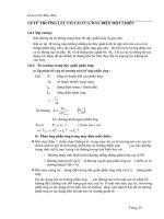
Two-Stage Direct Coal Liquefaction Processes
Process Developer
H
TI Coal Process or Catalytic Multi-Stage Liquefaction (CMSL) DOE and HTI (subsidiary of Headwaters, Inc.), USA
Catalytic Two-Stage Liquefaction (CTSL) DOE and HRI (predecessor of HTI), USA
Liquid Solvent Extraction (LSE) British Coal Corp., UK
Brown Coal Liquefaction (BCL) NEDO, Japan
Lummus Integrated Two-Stage Liquefaction (ITSL) Lummus, USA
Chevron Coal Liquefaction (CCLP) Chevron, USA
Kerr-McGee ITSL Kerr-McGee, USA
Consol Synthetic Fuel (CSF) Consol, USA
Mitsubishi Solvolysis MHI, Japan
Pyrosol Saarberwerke, Germany
Close-Coupled Two-Stage Liquefaction (CC-TSL) Amoco, USA
Supercritical Gas Extraction (SCE)
British Coal Corp., UK
Figure 2.2
29
Current Commercial Activity
In 1996, the DOE received an inquiry from the Chinese government asking for information on the most advanced
direct coal liquefaction available in the United States. The DOE recommended the HTI Coal Process and
introduced HTI to the Chinese in December of that year. The Chinese government put direct coal liquefaction
into its five-year plan and commissioned Shenhua Group (the largest coal company in China) to develop a direct
coal liquefaction project in Inner Mongolia, China.
Shenhua Group studied all of the commercially available direct coal liquefaction technologies from the United
States, Japan and Germany and in June 2002 signed a license agreement with HTI to apply HTI’s technology for
the first stage of a 50,000 bbl/d project. A process design package was supplied by HTI and engineering was
proceeding; however, Shenhua Group wanted to make some modifications to the technology contrary to the
advice of HTI. After further negotiation, a new agreement was drafted and signed that allowed Shenhua to use
and modify HTI’s technology for the first-stage of the 50,000 bbl/d project. Shenhua paid HTI the full license fee
for the technology applied to the first-stage and released HTI from any process performance guarantees.
In October 2004, HTI signed an agreement with Oil India Ltd. (OIL) to conduct testing and a feasibility study for
a commercial plant in the Assam state of India. The Assam coal is some of the best coal for direct coal
liquefaction because of its high reactivity and yield. Lab-scale tests have been completed and pilot plant testing
commenced in late 2005.
In February 2005, HTI signed a memorandum of understanding with the Philippines Department of Energy to
evaluate applying direct and/or indirect coal liquefaction in the Philippines. The Philippines’ government has
placed high priority on coal liquefaction and desires to make that country the hub for the coal liquefaction
industry in Southeast Asia. The first stage of the feasibility study was completed in September 2005.
Process Description
Coal is a solid organic material made up of large, complex molecules containing mostly carbon, plus small
amounts of hydrogen, sulfur, nitrogen and oxygen. Raw coal also contains moisture and solid particles of mineral
matter (ash). The aim of direct coal liquefaction is to break coal down into smaller component molecules, then to
add hydrogen, creating lighter and more stable oil molecules.
The process simultaneously removes sulfur
,
nitrogen and ash, resulting in a clean liquid fuel product.
Typical Direct Coal Liquefaction Process
In a typical direct coal liquefaction process, pulverized coal is dissolved in recycled coal-derived heavy process
liquid at about 170 bar and 425°C while hydrogen is added. Most of the coal structure is broken down in the
first-stage reactor. Liquefaction is completed in the second-stage reactor, at a slightly higher temperature and
lower pressure. A proprietary catalyst is dispersed in the slurry for both stages. A hydrotreater is incorporated
in the process to remove sulfur and nitrogen and open up the aromatic structure to achieve higher cetane levels,
thereby facilitating the downstream refining process. The bottom-of-the-barrel residue (material boiling above
455
°
C) is de-ashed and recycled as heavy process liquid.
The ash reject, containing residual carbon, can be fed
to the gasifier for use in production of hydrogen.
Indirect Coal Liquefaction
Indirect coal liquefaction involves first the gasification of coal to produce synthesis gas, followed by purification
to remove CO
2
and other contaminants, and then the conversion of the synthesis gas to liquid products using the
Fischer-Trospch synthesis process and associated product upgrading.
Historical Development
Indirect coal liquefaction was developed in Germany in 1923 based on work by Dr. Franz Fischer and Dr. Hans
T
ropsch. During World War II, the technology was used by Germany to produce 17,000 bbl/d of liquid fuels
from coal.
30
C
OAL-TO-LIQUIDS
A
fter the war, the Fischer-Tropsch synthesis technology was used by HRI (predecessor of HTI) to construct a
7,000 bbl/d gas-to-liquids plant in Brownsville, Texas, in 1949. The plant was operated by Cathage Hydrocol
from 1950 to 1953 before shutting down due to declining oil prices. The partial oxidation unit, used to convert
the natural gas into synthesis gas to feed the fixed-bed FT reactors at this plant, was the basis for what eventually
became the Texaco coal gasification process currently owned by GE Energy.
During this same time period (1950–53), Koelbel tested a 1.5 meter diameter slurry-phase FT reactor in
Rheinpreussen, Germany. By the mid-1950s, all of the German FT plants were shut down due to declining world
oil prices with discovery of abundant oil deposits in the Middle East.
While other countries were shutting down their FT plants, South Africa began commissioning its first indirect
coal liquefaction plant. Sasol was established in 1950 with the prime objective to convert low-grade coal into
petroleum chemicals and feedstocks. Sasol One was built in Sasolburg and produced its first liquid product in
1955. In 1969 the Natref crude oil refinery was commissioned, and in 1980 and 1982, Sasol Two and Sasol Three
respectively began production in Secunda. Today, Sasol produces the equivalent of 150,000 bbl/d of fuels and
petrochemicals from coal via the indirect liquefaction process. The process produces in excess of 40% of South
Africa’s liquid fuel requirements. Sasol manufactures more than 200 fuel and chemical products in Sasolburg and
Secunda in South Africa, as well as at several global locations.
The FT reactors installed in 1995 at Sasol One consisted of five tubular fixed-bed reactors with a capacity of 500
bbl/d each, and three circulating fluidized-bed reactors having a capacity of 2,000 bbl/d each. In 1980/1982,
Sasol installed 16 x 6,500 bbl/d circulating fluidized-bed reactors at Secunda. From this engineering ef
fort, it
became clear that the circulating fluidized-bed technology had reached its maximum scale-up potential. A new
generation 3,500 bbl/d (5-m diameter) fluidized-bed reactor was installed at Sasolburg in 1989. This led to the
further scale-up to an 11,000 bbl/d (8-m diameter) reactor in 1995 and the 20,000 bbl/d (10.7-m diameter) reactor
in 1998. Between 1995 and 1998, the 16 original circulating-fluidized-bed reactors at Secunda were replaced
with 4 x 11,000 bbl/d and 4 x 20,000 bbl/d fluidized-bed reactors. Sasol’s total capital investment for indirect
coal liquefaction from 1955 to 2000 exceeded $6 billion.
Interest in gas-to-liquids for monetizing stranded natural gas reserves has influenced most major oil companies to
invest billions of dollars (combined) in developing their own FT technology. Following is a list of FT
technologies that have reached at least the process development unit (PDU or large pilot-plant scale).
31
Most of the above companies are focused only on gas-to-liquids (GTL) rather than coal-to-liquids (CTL).
The noticeable exceptions are Sasol, Rentech Incorporated and the Institute of Coal Chemistry, which are active
in CTL. Shell is constructing a biomass-to-liquids (BTL) pilot plant in Freiberg, Germany. Iron or cobalt catalyst
can be used for indirect coal liquefaction, but iron catalyst offers an advantage in that it can operate with a lower
H
2
/CO ratio typically found in coal-derived syngas.
Current Commercial Activity
Major oil companies are currently spending, or planning to spend, in excess of $25 billion on gas-to-liquids
facilities in remote areas such as Qatar, Iran, Nigeria, Bolivia and Australia. Commercial activity on indirect coal
liquefaction projects has been less dramatic but is gaining momentum.
In 2004, Sasol reached agreement with the government of China to conduct a feasibility study on two 70,000 bbl/d
indirect coal liquefaction projects in China sponsored by Shenhua Group, Luneng Coal Chemicals, Ningxia Coal
Group and Sinopec. In July 2004, Yankuang Group started up a 480 bbl/d demo plant. The Institute of Coal
Chemistry announced that it is planning to set up a 3,900 bbl/d demo plant in China. And in August 2005, HTI
announced signing a license with UK RACE Investment Limited for setting up a 700 bbl/d demo plant in China.
Indirect coal liquefaction projects are also being studied in
Australia, Indonesia, India, Pakistan and the
Philippines. The United States has several indirect coal liquefaction projects under consideration. Following
is a list of those that have been discussed publicly.
FT Technologies
Licensor Reactor Catalyst Scale-Up Status
Sasol, South Africa Fluidized Bed Fe & Co 150,000 bbl/d CTL plants
and Slurry 30,000 bbl/d GTL plant
Shell, Netherlands Fixed Bed Co 12,500 bbl/d GTL plant
Statoil, Norway Slurry Co 1000 bbl/d GTL plant
ConocoPhillips, USA Slurry Co 400 bbl/d GTL demo
BP, UK Fixed Bed Co 300 bbl/d GTL demo
ExxonMobil, USA Slurry Co 300 bbl/d GTL demo
Rentech, USA Slurry Fe 235 bbl/d GTL demo
Syntroleum, USA Fixed Bed Co 70 bbl/d GTL PDU
Axens/ENI, France/Italy Slurry Co 20 bbl/d GTL PDU
Institute of Coal Chemistry, China Slurry Fe 20 bbl/d CTL PDU
Figure 2.3
32
C
OAL-TO-LIQUIDS
The Rentech projects in Illinois and Ohio involve coal-based integrated FT fuel and ammonia production.
A preliminary feasibility study has been completed on the Illinois project, and the first phase of front end
engineering and design (FEED) has begun. Most of the projects will involve production of some electricity
as well as FT
diesel and FT naphtha.
Process Description
Indirect coal liquefaction can operate on nearly any coal feedstock as long as the proper gasification and gas
cleaning technology are selected. Selection of the proper coal gasification technology is critical because it has
perhaps the biggest impact on the overall project cost.
Typical Indirect Coal Liquefaction Process
Figure 2.5
Source: NCC Working Group, September 2005
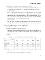
U.S. Indirect Coal Liquefaction Projects
State Developers Coal Type Capacity (bbl/d)
AZ Hopi Tribe, Headwaters Bituminous 10,000–50,000
MT State of Montana Sub-bit./Lignite 10,000–150,000
ND GRE, NACC, Lignite 10,000–50,000
Falkirk, Headwaters
WY DKRW Energy Bituminous 33,000
WY Rentech Mississippi 10,000–50,000
Sub-bit./Pet Coke
IL Rentech Bituminous 2,000
PA WMPI Anthracite 5,000
WV Mingo County Bituminous 10,000
Figure 2.4
33
I
n the gasification process, coal is partially oxidized with oxygen and steam to form carbon monoxide and hydrogen
rich syngas. The raw syngas is cooled and cleaned of carbon dioxide and other impurities such as hydrogen
sulfide, ammonia, halogens, cyanide and mercury. The H
2
/CO ratio of the syngas may be adjusted for optimum
FT performance. As the clean syngas passes through the FT reactor, it comes in contact with a proprietary catalyst
and forms long-chain paraffin hydrocarbons ranging from C1 to C100+ along with some oxygenates such
as water and alcohols. The tail gas can be recycled or sent to a gas turbine to generate electricity. The oxygenates
and distillable liquids are separated through fractionation. The wax and catalyst are separated through settling
and filtration. The wax is sent to a hydrocracker, where it is converted into distillable liquids using a catalyst
and hydrogen. The distillable liquids are hydrotreated and separated by fractionation into finished products such
as FT diesel and FT naphtha. The oxygenates can be used as feedstock for the gasifier or combusted to produce
electricity. The steam generated from cooling the syngas and from cooling the exothermic reactions in the
FT reactor can be sent to a steam turbine to generate additional electric power.
Comparison of Direct and Indirect Coal Liquefaction
Figure 2.6 compares typical product characteristics for direct and indirect coal liquefaction products. One of the
biggest differences between the two coal liquefaction technologies is that direct coal liquefaction makes high-
octane gasoline and low-cetane diesel, while indirect coal liquefaction produces high-cetane diesel and low-
octane gasoline. One other difference is that direct coal liquefaction products are denser and therefore tend to
have more Btus per gallon than indirect coal liquefaction products.
Hybrid Coal Liquefaction
Hybrid coal liquefaction integrates direct and indirect coal liquefaction into a single plant.
This concept takes
advantage of the complementary characteristics of the two processes. As mentioned above, direct coal
liquefaction makes high-octane gasoline and low-cetane diesel, while indirect coal liquefaction produces high-
cetane diesel and low-octane gasoline. Blending the products in an integrated plant allows production of
premium quality gasoline and diesel with minimal refining.
Final Product* Comparison
Type of Coal Liquefaction
Direct Indirect
Distillable product mix 65% diesel/35% naphtha 82% diesel/18% naphtha
Diesel cetane index 42–47 70–75
Diesel sulfur <5 ppm <1 ppm
Diesel aromatics 4.8 wt% <4 wt %
Diesel specific gravity 0.865 0.780
Naphtha octane (RON)
>100 45–75
Naphtha sulfur
<0.5 ppm
nil
Naphtha aromatics 5 wt % 2 wt %
Naphtha specific gravity
0.764
0.673
Figure 2.6 *After hydrotreating
34
C
OAL-TO-LIQUIDS
Historical Development
The concept of a hybrid DCL/ICL plant has been discussed for many years. The U.S. Department of Energy
commissioned MITRE Corporation to study the concept between 1990 and 1991. Initial studies indicated that
production costs were slightly lower for a hybrid plant compared to standalone direct or indirect plants. No
testing has been done on this concept to date.
Current Commercial Activity
HTI signed two license agreements in August 2005 with UK RACE Investment Limited for two 700 bbl/d plants
to be built in China. The first plant will be an indirect coal liquefaction plant, and the second plant will be a
direct coal liquefaction plant and will be integrated into the first plant to demonstrate the hybrid concept.
A feasibility study for a 60,000 bbl/d hybrid plant is currently being conducted in the Philippines by HTI in
cooperation with private and government entities.
Process Description
The synergy between the direct and indirect processes improves overall thermal efficiency of an integrated
hybrid plant. Higher-quality coal can be fed as feedstock to the direct coal liquefaction reactors, and lower-
quality coal can be fed to the gasifier to provide syngas for FT synthesis. The hydrogen-rich FT tail gas can be
used to provide hydrogen for product upgrading and for direct coal liquefaction.
Blending the raw distillable products prior to refining takes advantage of their complementary characteristics.
High-octane naphtha from direct coal liquefaction is blended with low-octane naphtha from indirect coal
liquefaction and high-cetane diesel from indirect coal liquefaction is blended with low-cetane diesel from direct
coal liquefaction. The blended liquids require less refining to meet premium product specifications than if they
were refined separately.
Typical Hybrid Coal Liquefaction Process
Figure 2.7
Coal
Raw ICL products
Raw DCL products
H
2
H
2
FT tail gas
Final
Products
Coal
Gasification
Indirect Coal
Liquefaction
(FT)
Product
Blending and
Refining
Hydrogen
Recovery
Direct Coal
Liquefaction
35
Co-Processing Coal and Heavy Oil
Co-processing of coal and heavy oil is worth considering if there is a low-cost source of heavy oil such as
bottom-of-the-barrel resid from a local refinery. The aim of co-processing coal and heavy oil is to simultaneously
break down the complex coal and heavy petroleum molecules into smaller distillable molecules, which can be
further refined into clean liquid fuel products.
Co-processing can be technically and economically more appealing than direct coal liquefaction because it
eliminates the need for recirculating a large stream of internally generated process-derived liquids and lowers the
required capital and operating cost. However, co-processing production costs may be higher than direct coal
liquefaction production costs if the resid is significantly more expensive than coal on an energy basis.
Historical Development
Co-processing was first tested in 1974 at HRI (now HTI) test facilities in Lawrenceville, New Jersey. Bench-
scale tests were conducted on a wide range of materials in the early to mid-1980s. In 1989, tests were run on
Ohio coal and Cold Lake resid in the 30 bbl/d process development unit. In the 1990s, co-processing tests were
run for customers in Nova Scotia, China, India and Indonesia. A co-processing pilot plant was built in Duliajan,
Assam, India, in 1994.
Process Description
In co-processing, a preheated mixture of pulverized coal, catalyst, resid (may also contain a small amount of
recycle liquid) and hydrogen is fed into the first of two reactors at a temperature of 435°–460°F and pressure of
170 bars. Most of the coal and resid structure is broken down in the first-stage reactor. Hydrocracking of the
intermediate coal and resid products is completed in the second-stage reactor. The distillable products pass
through a mild hydrotreater and then further upgraded using conventional refining techniques to produce
gasoline, as well as jet and diesel fuels that will meet or exceed existing and planned fuel specifications.
Co-Processing Liquefaction Process
Figure 2.8
C–C
H S, NH , CO
Refining
Coal
Liquefaction
HTU
Fractionation
C
1
–C
2
H
2
S, NH
3
, CO
x
Make-up H
2
Coal + Catalyst
Slurry
Recycle H
Diesel Fuel
Gasoline
LPG
HVGO
Ash Slurry
Gas Recovery
Treatment
Resid
36
C
OAL-TO-LIQUIDS
Mild Pyrolysis
Mild pyrolysis is a method of obtaining liquid fuels from coal by heating the coal in an oxygen-free atmosphere,
vaporizing the volatile material, and then condensing out the hydrocarbon liquids from the product vapors. This
technique is perhaps the oldest method of extracting liquid fuels from coal, but yields and product quality are
very low.
Historical Development
At least three mild pyrolysis technologies were developed to pilot-plant scale in the United States in the 1980s.
The processes differed mainly in the design of the pyrolyzing reactor. One process, the liquids from coal
(LFC) process, was scaled up to a 1,000 stpd demo plant in 1992. The LCF process was developed by
SGI International. The demo plant was built in Gillette, Wyoming and owned by Encoal Corporation.
Funding was provided by the U.S. Department of Energy Clean-Coal Technology Demonstration Program.
The plant operated up and down for a few years before shutting down. The plant has changed ownership several
times since starting up.
Process Description
Mild pyrolysis favors use of high-volatile coals. It consists of heating coal to a temperature in the range of
450°–650
°C in an oxygen-free atmosphere, driving off volatile matter from the coal, generating other volatile
organic compounds, and condensing out the distillable liquids. Liquid yield is typically less than 20%. The main
product is char with a reduced hydrogen, sulfur and nitrogen content.
In a typical mild pyrolysis process, coal is crushed and screened and then heated by a hot gas stream in a rotary-grate
dryer. The dried coal is then fed into the main rotary-grate pyrolyzer, where it is heated to about 540°C by a hot
recycle gas stream. Upon dischar
ge from the pyrolyzer
, the solids are passed to a deactivation step and are then
cooled in an indirect rotary drum cooler. The gas from the pyrolyzer is cooled in a quench tower condensing out
the distillable liquids.
The gases are then recycled to provide fuel for the process.
The liquid fuel produced in this
process is roughly equivalent to a No. 6 fuel oil.
Typical Mild Pyrolysis Process
Figure 2.9
Coal
Cyclone
Dryer
Rotary Cooler
Pyrolyzer
Char
Deactivation
Combustor
Combustor
Cyclone Scrubber
Condensation ESP
Char
Liquids Fuel
Flue
Gas
37
REFERENCES
Burke, F.P.; Brandes, S.D.; McCoy, D.C.; Winschel, R.A.; Gray, D.; and Tomlinson, G., “Summary Report of the
DOE Direct Liquefaction Process Development Campaign of the Late Twentieth Century: Topical Report,” the
DOE Contract DE-AC22-94PC9354, pp. 12–13, July 2001.
Department of Trade and Industry, “Technology Status Report — Coal Liquefaction,” October 1999, pp. 2–3.
Gray, D., Tomlinson, G.C., ElSawy, A., “The Hybrid Plant Concept: Combining Direct and Indirect Coal
Liquefaction Processes,” the U.S. DOE Indirect Liquefaction Contractor’s Review Meeting Proceedings,
Pittsburgh, PA, November 6–8, 1990, pp. 299–316.
38
C
OAL-TO-LIQUIDS