INTERNATIONAL ENERGY CONSERVATION CODE phần 7 pot
Bạn đang xem bản rút gọn của tài liệu. Xem và tải ngay bản đầy đủ của tài liệu tại đây (213.71 KB, 10 trang )
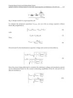
where:
F The measured leakage rate in cfm per 100
square feet
of
duct surface.
P The static pressure
of
the test.
Documentation shall be furnished by the designer
demonstrating that representative sections totaling at
from the building exterior or unconditioned or exempt
spaces by a minimum
of
R
-8
insulation.
Exceptions:
1.
When located within equipment.
2.
When the design temperature difference between
the interior and exterior
of
the duct orplenum does
not exceed 15°F (8°C).
All ducts, air handlers and filter boxes shall be sealed.
Joints and seams shall comply with Section 603.9
of
the
International Mechanical Code.
503.2.7.1 Duct construction. Ductwork shall be con-
structed and erected in accordancewith the
International
Mechanical Code.
503.2.7.1.1 Low-pressure duct systems.
Alliongi-
tudinal and transverse joints, seams and connections
of
supply and return ducts operating at a static pres-
sure less than or equal to 2 inches w.g. (500
Pa)
shall
be securely fastened and sealed with welds, gaskets,
mastics (adhesives), mastic-plus-embedded-fabric
systems or tapes installedin accordancewith the man-
ufacturer,s installation instructions. Pressure classifi-
cations specific
to
the duct system shall be clearly
indicated on the construction documents in accor-
dance with the
International Mechanical Code.
Exception:
Continuously
welded
and
lock-
ing-type longitudinal joints and seams on ducts
operating at static pressures less than 2 inches w.g.
(500 Pa) pressure classification.
503.2.7.1.2 Medium-pressure duct systems. All
ducts and plenums designed
to
operate at astatic pres-
sure greater than 2 inches w.g. (500
Pa)
but less than 3
inches w.g. (750
Pa)
shall be insulated and sealed in
accordance with Section 503.2.7. Pressure classifica-
tions specific to the duct system shall be clearly indi-
cated on the construction documents in accordance
with the
International Mechanical Code.
503.2.7.1.3 High-pressure
duct
systems. Ducts
designed to operate at static pressures in excess
of
3
inches w.g. (746
Pa)
shall be insulated and sealed in
accordance with Section 503.2.7. In addition, ducts
and plenums shall be leak-tested in accordance with
the SMACNA
HVAC
Air
DuctLeakage Test Manual
with the rate
of
air leakage
(CL)
less than or equal to
6.0 as determined in accordance with Equation 5-2.
COMMERCIAL ENERGY EFFICIENCY
4.
Spaces where the supply airflow rate
minus any makeup or outgoing transfer
air requirement is less than 1,200 cfm
(600
Lis).
503.2.6 Energy recovery ventilation systems. Individual
fan systems that have both a design supply air capacity
of
5,000 cfm (2.36 m
3
/s)
or greater and a minimum outside air
supply
of
70 percent or greater
of
the design supply air
quantity shall have an energy recovery system that provides
a change in the enthalpy
of
the outdoor air supply
of
50 per-
cent or more
of
the difference between the outdoor air and
return air at design conditions. Provision shall be made to
bypass or control the energy recovery system to permit
cooling with outdoor air where cooling with outdoor air is
required.
Exception: An energy recovery ventilation system shall
not be required in any
of
the following conditions:
1.
Where energy recovery systems are prohibited by
the
International Mechanical Code.
2.
Laboratory fume hood systems that include at least
one
of
the following features:
2.1. Variable-air-volume hood exhaust and
room supply systems capable
of
reducing
exhaust and makeup air volume to 50 per-
cent or less
of
design values.
2.2. Direct makeup (auxiliary) air supply equal
to at least
75
percent
of
the exhaust rate,
heated no warmer than 2°F (1.I
O
C)
below
room setpoint, cooled to no cooler than 3
OF
(I.7°C)
above
room
setpoint,
no
humidification added, and no simulta-
neous
heating
and
cooling
used
for
dehumidification control.
3.
Systems serving spaces that are not cooled and are
heated to less than 60°F (I5.5°C).
4.
Where more than 60 percent
of
the outdoor heating
energy is provided from site-recovered or site
solar energy.
5.
Heating systems in climates with less than 3,600
HDD.
6.
Cooling systems in climates with a I-percent cool-
ing design wet-bulb temperature less than 64°F
(18°C) .
7.
Systems requiring dehumidification that employ
series-style energy recovery coils wrapped around
the cooling coil.
503.2.7 Duct
and
plenum insulation
and
sealing. All sup-
ply and return air ducts and plenums shall be insulated with
a minimum
of
R-5 insulation when located in uncondi-
tioned spaces and a minimum
of
R-8 insulation when
located outside the building. When locatedwithin a building
envelope assembly, the duct or plenum shall be separated
CL=
Fx
pO
.
65
(Equation
5-2)
50
2009 INTERNATIONAL ENERGY CONSERVATION
CODE®
least 25 percent
of
the duct area have been tested and
that all tested sections meet the requirements
of
this
section.
503.2.8 Piping insulation. All piping serving as part
of
a
heating or cooling system shall be thermally insulated in
accordance with Table 503.2.8.
Exceptions:
1.
Factory-installed piping within HVAC equipment
tested and rated in accordance with a test proce-
dure referenced by this code.
2.
Factory-installed piping within room fan-coils and
unitventilators tested and rated according to AHRI
440 (except that the sampling and variation provi-
sions
of
Section 6.5 shall not apply) and 840,
respectively.
3.
Piping that conveys fluids that have a design oper-
ating temperature range between 55°F (13°C) and
105°F (41°C).
4.
Piping that conveys fluids that have not been
heated or cooled through the use
of
fossil fuels or
electric power.
5.
Runout piping not exceeding 4 feet (1219 mm) in
length and 1 inch
(25
mm) in diameter between the
control valve and HVAC coil.
TABLE 503.2.8
MINIMUM PIPE INSULATION
(thickness in inches)
NOMINAL PIPE DIAMETER
FLUID
~
1.5" > 1.5"
Steam 1
1
/
2
3
Hot water 1
1
/
2
2
Chilled water, brine or refrigerant 1
1
/
2
1
1
/
2
For SI: 1 inch = 25.4
mm
.
a. Based
on
insulation having a conductivity
(k)
not exceeding 0.27 Btu per
inch/h.
ft2
.
oF.
b. For insulationwitha thermal conductivity not equal to 0.
27
Btu·
inch/h·
ft2
.
OF
at a meantemperature
of
75°F, the minimumreqUired pipe thickness is adjusted
using the following equation;
T=
r[
(l +
tir)
IVk
-1]
where:
T Adjusted insulation thickness (in).
r Actual pipe radius (in) .
Insulation thickness from applicable cell in table (in) .
K
New
thermal conductivity at 75°F (Btu · inlhr ·
ft
2.
OF)
.
k 0.27 Btu · in/hr · fe .
OF
.
503.2.9
HVAC
system completion. Prior to the issuance
of
a certificate
of
occupancy, the design professional shall pro-
vide evidence
of
system completion in accordance with
Sections 503.2.9.1 through 503.2.9.3.
2009 INTERNATIONAL ENERGY CONSERVATION
CODE®
COMMERCIAL ENERGY EFFICIENCY
503.2.9.1 Air system balancing. Each supply air outlet
and
zone terminal device shall be equipped with means
for air balancing in accordance with the requirements
of
Chapter 6
of
the International Mechanical Code. Dis-
charge dampers are prohibited on constant volume fans
and variable volume fans with motors
10
horsepower
(hp) (7.4 kW) and larger.
503.2.9.2
Hydronic
system balancing.
Individual
hydronic heating and cooling coils shall be equipped
with means for balancing and pressure test connections.
503.2.9.3 Manuals. The construction documents shall
require that an operating and maintenance manual be
provided to the building owner by the mechanical con-
tractor. The manual shall include, atleast, the following:
1.
Equipment
capacity
(input
and
output)
and
required maintenance actions.
2.
Equipment operation and maintenance manuals.
3.
HV
AC system control maintenance and calibra-
tion information, including wiring diagrams, sche-
matics,
and
control
sequence
descriptions.
Desired or field-determined setpoints shall be per-
manently recorded on control drawings, at control
devices or, for digital control systems, in program-
ming comments.
4.
A complete written narrative
of
how each system
is intended to operate.
503.2.10 Air system design
and
control. Each HVAC sys-
tem having a total fan system motor nameplate horsepower
(hp) exceeding 5 horsepower
(hp)
shall meet the provisions
of
Sections 503.2.10.1 through 503.2.10.2.
503.2.10.1 Allowable fan floor horsepower. Each
HVAC system at fan system design conditions shall not
exceed the allowable fan system motor nameplate hp
(Option
1)
or fan system bhp (Option
2)
as shown in
Table
503.2.10.1
(1).
This
includes
supply
fans,
return/relieffans, and fan-powered terminal units associ-
ated with systems providing heating or cooling capabil-
ity.
Exceptions:
1.
Hospital and laboratory systems that utilize
flow control devices onexhaustand/or return to
maintain space pressure relationships neces-
sary for occupant health and safety or environ-
mental
control
shall
be
permitted
to
use
variable volume fan power limitation.
2.
Individual exhaust fans with motor nameplate
horsepower
of
1 hp or less.
3.
Fans exhausting air from fume hoods. (Note:
If
this exception is taken, no related exhaust side
credits shall be taken from Table 503.2.10.1
(2)
and the Fume Exhaust Exception Deduction
must be taken from Table 503.2.10.1 (2).
51
COMMERCIAL ENERGY EFFICIENCY
TABLE 503.2.10.1(1)
FAN POWER LIMITATION
LIMIT CONSTANT VOLUME VARIABLE VOLUME
Option 1: Fan system motor nameplate hp Allowable nameplate motor hp hp
~
CFM
s
*0
.0011 hp
~
CFM
s
*0
.0015
Option 2: Fan system bhp Allowable fan system bhp bhp
~
CFM
s
*0.00094 + A bhp
~
CFM
s
*0.0013 + A
where:
CFM
s
= The maximum design supply airflow rate to conditioned spaces served by the system in cubic feet per minute.
hp
= The maximum combined motor nameplate horsepower.
Bhp
= The maximum combined fan brake horsepower.
A = Sum
of
[PDx CFM
D
/4131].
where:
PD
= Each applicable pressure drop adjustment from Table 503.2.10.1
(2)
in. w.c.
TABLE 503.2.10.1 (2)
FAN POWER LIMITATION PRESSURE DROP ADJUSTMENT
DEVICE ADJUSTMENT
Credits
Fully ducted return and/or exhaust air systems 0.5 in w.
c.
Return and/or exhaust airflow control devices 0.5 in w.c
Exhaust filters, scrubbers or other exhaust treatment.
The pressure drop
of
device calculated at fan system design
condition.
Particulate filtration credit: MERV 9 thru
12
0.5 in w.c.
Particulate filtration credit: MERV
13
thru
15
0.9 in w.c.
Particulate filtration credit: MERV
16
and greater and electronically Pressure drop calculated at 2x clean filter pressure drop at fan system
enhanced filters design condition.
Carbon and other gas-phase air cleaners Clean filter pressure drop at fan system design condition.
Heat recovery device Pressure drop
of
device at fan system design condition.
Evaporative humidifier/cooler in series with another cooling coil Pressure drop
of
device at fan system design conditions
Sound attenuation section
0.
15
in w.
c.
Deductions
Fume hood exhaust exception
-1
.0 in w.c.
(required
if
Section 503.2.10.1, Exception
3,
is taken)
52
503.2.10.2 Motor nameplate horsepower. For each
fan, the selected fan motor shall be no larger than the first
available motor size greater than the brake horsepower
(bhp). Thefan brake horsepower (bhp) shall be indicated
on the design documents to allow for compliance verifi-
cation by the
code official.
Exceptions:
1.
For fans less than 6 bhp, where the first avail-
able motor larger than the brake horsepower
has a nameplate rating within
50 percent
of
the
bhp, selection
of
the next larger nameplate
motor size is allowed.
2.
For fans 6 bhp and larger, where the first avail-
able motor larger than the bhp has a nameplate
rating within
30 percent
of
the bhp, selection
of
the nextlargernameplate motorsize is allowed.
503.2.11
Heating outside a building. Systems installed to
provide heat outside a building shall be radiant systems.
Such heating systems shall be controlled by an occupancy
I
sensing device or a timer switch, so that the system is auto-
matically deenergized when no occupants are present.
503.3
Simple
HVAC
systems
and
equipment (Prescriptive).
This section applies to buildings servedby unitary or packaged
HVAC
equipment
listed
in
Tables
503.2.3
(1)
through
503.2.3(5), each serving one zone and controlled by a single
thermostat in the zone served. It also applies to two-pipe heat-
ing systems serving one or more zones, where no cooling sys-
tem is installed.
This section does not apply to fan systems serving multiple
zones, nonunitary or nonpackaged HVAC equipment and sys-
tems or hydronic or steam heating and hydronic cooling equip-
ment and distribution systems that provide cooling or cooling
and heating which are covered by Section
503.4.
503.3.1 Economizers. Supply air economizersshall be pro-
vided on eachcoolingsystemas shown in Table
503.3.1 (1).
2009 INTERNATIONAL ENERGY CONSERVATION CODE®
Economizers shall be capable
of
providing 100-percent
outdoor air, even
if
additional mechanical cooling is
required to meet the cooling load
of
the building. Systems
shall provide a means to relieve excess outdoor air during
economizer operation
to
prevent overpressurizingthe build-
ing. The relief air outlet shall be located to avoid
recirculation into the building. Where a single room or
space is supplied by multiple air systems, the aggregate
capacity
of
those systems shall be used in applying this
requirement.
Exceptions:
1.
Where the cooling equipment is covered by the
minimum
efficiency
requirements
of
Table
503.2.3(1) or 503.2.3(2) and meets or exceeds the
minimum cooling efficiency requirement (EER)
by the percentages shown in Table 503.3.1 (2).
2.
Systems
with
air
or
evaporatively
cooled
condensors and which serve spaces with open case
refrigeration or that require filtration equipment in
order to meet the minimum ventilation require-
ments
of
Chapter 4
of
the International Mechani-
cal Code.
TABLE 503.3.1 (1)
ECONOMIZER REQUIREMENTS
CLIMATE ZONES ECONOMIZER REQUIREMENT
lA,
IB, 2A,
7,
8
No requirement
2B, 3A, 3B, 3C, 4A, 4B,
Economizers on all cooling systems
4C,
SA,
5B, 5C, 6A, 6B
~
54,000 Btu/h
a
For SI: 1 British thermal unit per hour = 0.293 W
I
a.
The total capacity
of
all systems without economizers shall not exceed
480,000 Btu/h per building, or
20
percent
of
its air economizer capacity,
whichever is greater.
TABLE 503.3.1 (2)
EQUIPMENT EFFICIENCY PERFORMANCE
EXCEPTION FOR ECONOMIZERS
COOLING EQUIPMENT PERFORMANCE
CLIMATE ZONES IMPROVEMENT (EER OR IPLV)
2B 10% Efficiency Improvement
3B 15% Efficiency Improvement
4B 20% Efficiency Improvement
503.3.2 Hydronicsystem controls. Hydronic systems
of
at
least 300,000
Btu/h (87,930
W)
design output capacity sup-
plying heatedand chilledwater
to
comfortconditioning sys-
tems shall include controls that meet the requirements
of
Section 503.4.3.
503.4 Complex
HVAC
systems
and
equipment. (Prescrip-
tive). This section applies
to
buildings served by
HVAC
equip-
ment and systems not covered in Section 503.3.
503.4.1 Economizers. Supply air economizers shall be pro-
vided on each cooling system according to Table
503.3.1 (1). Economizers shall be capable
of
operating at
2009 INTERNATIONAL ENERGY CONSERVATION CODE®
COMMERCIAL ENERGY EFFICIENCY
100 percent outside air, even
if
additional mechanical cool-
ing is required to meet the cooling load
of
the building.
Exceptions:
1.
Systems utilizing watereconomizers thatare capa-
ble
of
cooling supply air by direct or indirect evap-
oration or both and providing 100 percent
of
the
expected system cooling load at outside air tem-
peratures
of
50°F (10°C) dry bulb/45°F (7°C) wet
bulb and below.
2.
Where the cooling equipment is covered by the
minimum
efficiency
requirements
of
Table
503.2.3(1),503.2.3(2), or 503.2.3(6) and meets or
exceeds the minimum EER by the percentages
shown in Table 503.3.1
(2)
3.
Where the cooling equipment is covered by the
minimum
efficiency
requirements
of
Table
503.2.3(7) and meets or exceeds the minimum
integrated part load value (IPL
V)
by the percent-
ages shown in Table 503.3.1
(2).
503.4.2 Variable
air
volume
(VAV)
fan control. Individual
VA
V fans with motors
of
10 horsepower (7.5 k
W)
or greater
shall be:
1.
Driven by a mechanical or electrical variable speed
drive; or
2.
The fan motor shall have controls or devices that will
result in fan motordemand
of
no more than 30 percent
of
their design wattage at 50 percent
of
design airflow
when static pressure set point equals one-third
of
the
total design static pressure, based on manufacturer's
certified fan data.
For systems with direct digital control
of
individual zone
boxes reporting
to
the central control panel, the static pres-
sure set point shall be reset based on the
zone requiring the
most pressure, Le., the set point is reset lower until one
zone
damper is nearly wide open.
503.4.3 Hydronic systems controls. The heating
of
fluids
that have been previously mechanicallycooled and the cool-
ing
of
fluids that have been previously mechanically heated
shall be limited in accordance with Sections 503.4.3.1
through 503.4.3.3. Hydronic heating systems comprised
of
multiple-packaged boilers and designed to deliver condi-
tioned water or steam into a common distribution system
shall include automatic controls capable
of
sequencing
operation
of
the boilers. Hydronic heating systems com-
prised
of
a single boiler and greater than 500,000 Btu/h
input design capacity shall include either a multistaged or
modulating burner.
503.4.3.1 Three-pipe system. Hydronic systems that
use a common return system for both hot water and
chilled water are prohibited.
503.4.3.2 Two-pipe changeover system. Systems that
use a common distribution system to supply both heated
and chilled water shall be designed to allow a dead band
between changeover from one mode to the other
of
at
least 15°F (8.3°C) outside air temperatures; be designed
to and provided with controls that will allow operation in
53
COMMERCIAL
ENERGY EFFICIENCY
one mode for at least 4 hours before changing over to the
other mode; and be provided with controls that allow
heating and cooling supply temperatures at the change-
over point
to
be no more than 30°F (16.7°C) apart.
503.4.3.3 Hydronic (water loop) heat
pump
systems.
Hydronic heat pump systems shall comply with Sections
503.4.3.3.1 through 503.4.3.3.3.
503.4.3.3.1 Temperature dead band. Hydronic heat
pumps connected to a common heat pump water loop
with central devices for heat rejection and heat addi-
tion shall have controls thatare capable
of
providing a
heat pump water supply temperature dead band
of
at
least 20°F (11. 1°C) between initiation
of
heat rejec-
tion and heat addition by the central devices.
Exception: Where a system loop temperature
optimization controller is installed and can deter-
mine the most efficient operating temperature
based on realtime conditions
of
demand and
capacity, dead bands
of
less than 20°F (11°C) shall
be permitted.
503.4.3.3.2 Heatrejection. Heat rejection equipment
shall
comply
with
Sections
503.4.3.3.2.1
and
503.4.3.3.2.2.
Exception: Where it can be demonstrated that a
heat pump system will be required
to
reject heat
throughout the year.
503.4.3.3.2.1 Climate Zones 3
and
4.
For Climate
Zones 3 and 4 as indicated in Figure 301.1 and
Table 301.1:
1.
If
a closed-circuit cooling tower is used
directly in the heat pump loop, either an
automatic valve shall be installed to bypass
all but a minimal flow
of
water around the
tower, or lower leakage positive closure
dampers shall be provided.
2.
If
an open-circuit tower is used directly in
the heat pump loop, an automatic valve shall
be installed
to
bypass all heat pump water
flow around the tower.
3.
If
an open- or closed-circuit cooling tower is
used in conjunction with a separate heat
exchanger to isolate the cooling tower from
the heat pump loop, then heat loss shall be
controlled by shutting down the circulation
pump on the cooling tower loop.
503.4.3.3.2.2 Climate Zones 5through
8.
For cli-
mate Zones 5 through 8 as indicated in Figure
301.1 and Table 301.1,
if
an open- or closed-circuit
cooling
tower
is used, then a
separate
heat
exchanger shall be required to isolate the cooling
tower from the heat pump loop, and heat loss shall
be controlled by shutting down the circulation
pump on the cooling tower loop and providing an
automatic valve
to
stop the flow
of
fluid.
54
503.4.3.3.3 Two position valve. Each hydronic heat I
pump on the hydronic system having a total pump
system power exceeding 10 horsepower
(hp)
(7.5
kW) shall have a two-position valve.
503.4.3.4
Part
load controls. Hydronic systems greater
than or equal to 300,000 Btu/h
(87
930
W)
in design out-
put capacitysupplying heated or chilledwaterto comfort
conditioning systems shall include controls that have the
capability to:
1.
Automatically reset the supply-water tempera-
tures using zone-return water temperature, build-
ing-return
water
temperature,
or
outside air
temperature as an indicator
of
building heating or
cooling demand. The temperature shall be capable
of
being reset by at least
25
percent
of
the design
supply-to-return water temperature difference; or
2.
Reduce system pump flow by at least 50 percent
of
design flow rate utilizing adjustable speed drive
(s)
on pump(s), or multiple-staged pumps where at
least one-half
of
the total pump horsepower is
capable
of
being automatically turned
off
or con-
trol valves designed to modulate orstep down, and
close, as a function
of
load, or other approved
means.
503.4.3.5
Pump
isolation. Chilled water plants includ-
ing more than one chiller shall have the capability to
reduce flow automatically through the chillerplant when
a chiller is shut down. Chillers piped in series for the pur-
pose
of
increased temperature differential shall be con-
sidered as one chiller.
Boilerplants includingmore than one boilershall have
the capability to reduce flow automatically through the
boiler plant when a boiler is shut down.
503.4.4 Heat rejection equipment fan speed control.
Each fan powered by a motor
of
7.5 hp (5.6 kW) or larger
shall have the capability to operate that fan at two-thirds
of
full speed or less, and shall have controls that automatically
change the fan speed to control the leaving fluid tempera-
ture or condensing temperature/pressure
of
the heat rejec-
tion device.
Exception: Factory-installed heat rejection devices I
within HVAC equipment tested and rated in accordance
with Tables 503.2.3(6) and 503.2.3(7).
503.4.5 Requirements for complex mechanical systems
serving multiple zones.
Sections 503.4.5.1 through
503.4.5.3 shall apply to complex mechanical systems serv-
ing multiple zones. Supply air systems serving multiple
zones shall be
VAV
systems which, during periods
of
occu-
pancy, are designed and capable
of
being controlled to
reduce primary air supply to each
zoneto one
of
the follow-
ing before reheating, recooling or mixing takes place:
1.
Thirty percent
of
the maximum supply air to each
zone.
2009
INTERNATIONAL
ENERGY CONSERVATION CODE®
2.
Three hundred cfm (142 Lis) or less where the maxi-
mum flow rate is less than
10
percent
of
the total fan
system supply airflow rate.
3.
The minimum ventilation requirements
of
Chapter 4
of
the International Mechanical Code.
Exception: The following define when individual zones
or when entire air distribution systems are exempted
from the requirement for
VAV
control:
1.
Zones where special pressurization relationships
or cross-contamination requirements are such that
VAV systems are impractical.
2.
Zones or supply air systems where at least
75
per-
cent
of
the energy for reheating or for providing
warm air in mixing systems is provided from a
site-recovered or site-solar energy source.
3.
Zones where special humidity levels are required
to satisfy process needs.
4.
Zones with a peak supply air quantity
of
300 cfm
(142 Lis) or less and where the flow rate is less than
10 percent
of
the total fan system supply airflow
rate.
5.
Zones where the volume
of
air to be reheated,
recooled or mixed is no greater than the volume
of
outside air required to meet the minimum ventila-
tion requirements
of
Chapter 4
of
the International
Mechanical Code.
6.
Zones or supply air systems with thermostatic and
humidistatic controls capable
of
operating in
sequence the supply
of
heating and cooling energy
to the zone(s) and which are capable
of
preventing
reheating, recooling, mixing or simultaneous sup-
ply
of
air that has been previously cooled, either
mechanically or through the use
of
economizer
systems, and air that has been previously mechani-
cally heated.
503.4.5.1 Single duct variable
air
volume
(VAV)
sys-
tems, terminal devices.
Single duct
VAV
systems shall
use terminal devices capable
of
reducing the supply
of
primary supply air before reheating or recooling takes
place.
503.4.5.2 Dual duct
and
mixing
VAV
systems, termi-
nal devices. Systems that have one warm air duct and
one cool air duct shall use terminal devices which are
capable
of
reducing the flow from one duct to a minimum
before mixing
of
air from the other duct takes place.
503.4.5.3 Single fan dual duct
and
mixing
VAV
sys-
tems, economizers.
Individual dual duct or mixing heat-
ing and cooling systems with a single fan and with total
capacities greater than 90,000 Btulh [(26 375
W)
7.5
tons] shall not be equipped with air economizers.
503.4.5.4 Supply-airtemperature reset controls. Mul-
tiple zone
HVAC
systems shall include controls that
automatically
reset the
supply-air
temperature
in
response to representative building loads, or to outdoor
air temperature. The controls shall be capable
of
reset-
2009 INTERNATIONAL ENERGY CONSERVATION CODE®
COMMERCIAL ENERGY EFFICIENCY
ting the supply air temperature at least
25
percent
of
the
difference between the design supply-air temperature
and the design room air temperature.
Exceptions:
1.
Systems that prevent reheating, recooling or
mixing
of
heated and cooled supply air.
2.
Seventyfive percent
of
the energy for reheating
is from site-recovered or site solar energy
sources.
3.
Zones with peak supply air quantities
of
300
cfm (142 Lis) or less.
503.4.6 Heat recovery for service water heating. Con-
denser heat recovery shall be installed for heating or reheat-
ing
of
service hot water provided the facility operates
24
hours a day, the total installed heat capacity
of
water-cooled
systems exceeds 6,000,000 Btulhr
of
heat rejection, and the
design service waterheating load exceeds 1,000,000 Btu/h.
The required heat recovery system shall have the capacity
to provide the smaller of:
1.
Sixty percent
of
the peak heat rejection load at design
conditions; or
2.
The preheating required to raise the peak service hot
water draw to 85°F (29°C).
Exceptions:
1.
Facilities that employ condenser heat recovery for
space heating orreheat purposes with a heatrecov-
ery design exceeding 30 percent
of
the peak
water-cooled condenserloadatdesign conditions.
2.
Facilities that provide 60 percent
of
their service
water heating from site solar or site recovered
energy or from other sources.
SECTION 504
SERVICE WATER HEATING
(Mandatory)
504.1 General. This section covers the minimum efficiency of,
and controls for, service water-heating equipment and insula-
tion
of
service hot water piping.
504.2 Service water-heating equipment performance effi-
ciency.
Water-heating equipment and hot water storage tanks
shall meet the requirements
of
Table 504.2. Theefficiency shall
be verified through data furnished by the manufacturer or
through certificationunder an approvedcertification program.
504.3 Temperature controls. Service water-heating equip-
ment shall be provided with controls to allow a setpoint
of
110°F (43°C) for equipment serving dwelling units and
gO°F
(32°C) for equipment serving other occupancies. The outlet
temperature
of
lavatories in public facility rest rooms shall be
limited to 110°F (43°C) .
504.4 Heat traps. Water-heating equipment not supplied with
integral heat traps and serving noncirculating systems shall be
provided with heat traps on the supply and discharge piping
associated with the equipment.
55
COMMERCIAL ENERGY EFFICIENCY
TABLE 504.2
MINIMUM PERFORMANCE OF WATER-HEATING EQUIPMENT
SIZE CATEGORY SUBCATEGORY OR PERFORMANCE TEST
EQUIPMENT TYPE (input) RATING CONDITION
REQUIREDa,
b
PROCEDURE
~12kW
Resistance 0.97 - 0.00132
v:
EF DOE
10
CFR Part 430
Water heaters,
>12kW
Resistance 1.73 V+ 155 SL, Btu/h ANSI Z21.10.3
Electric
~
24
amps and
Heat pump 0.93 - 0.00132
v:
EF DOE
10
CFR Part 430
~
250 volts
~
75,000 Btu/h
~
20 gal 0.67 - 0.0019
v:
EF DOE
10
CFR Part 430
Storage water heaters,
> 75,000 Btu/h and
< 4,000 Btu/h/gal
80%E
t
~
155,000 Btu/h
( Q/ 800 + 110
JV
)SL,
Btu/h
Gas
ANSI Z21.10.3
80%E
> 155,000 Btu/h < 4,000 Btu/h/gal
( Q/
800
+
110#)
SL,
Btulh
> 50,000 Btu/h and
~
4,000 (Btu/h)/gal
0.62 - 0.0019
v:
EF DOE
10
CFR Part 430
< 200,000 Btu/he
and < 2 gal
Instantaneous water heaters,
~
200,000 Btu/h
~
4,000 Btu/h/gal and
80%E
t
Gas
<
10
gal
ANSI Z21.10.3
~
4,000 Btu/h/gal and
80%E
~
200,000 Btu/h
~
10
gal
( Q/
800
+
110#)
SL,
Btulh
~
105,000 Btu/h
~
20 gal 0.59 - 0.0019
v:
EF DOE
10
CFR Part 430
Storage water heaters,
Oil
> 105,000 Btu/h < 4,000 Btu/h/gal
78%E
ANSI Z21 .
10
.3
( Q/
800
+
Ilo-JV)
SL
, Btulh
~
210,000 Btu/h
~
4,000 Btu/h/gal and
0.59 - 0.0019
v:
EF DOE
10
CFR Part 430
< 2 gal
Instantaneous water heaters,
> 210,000 Btu/h
~
4,000 Btu/h/gal and
80%E
t
Oil
<
10
gal
ANSI Z21.10.3
> 210,000 Btu/h
~
4,000 Btu/h/gal and
78%E
~
10
gal
( Q/
800
+
110#)
SL
, Btulh
Hot water supply boilers,
~
300,000 Btu/h and
~
4,000 Btu/h/gal and
80%E
t
Gas and Oil <12,500,000 Btu/h
<
10
gal
Hot water supply boilers,
~
300,000 Btu/h and
~
4,000 Btu/h/gal and
80%E
Gas <12,500,000 Btu/h
~
10
gal
( Q/
800
+
Ilo-JV)
SL,
Btulh
ANSI Z21.10.3
Hot water supply boilers, > 300,000 Btu/h and > 4,000 Btu/h/gal and
78%E
Oil <12,500,000 Btu/h
>
10
gal
( Q/
800
+
110#)
SL,
Btulh
Pool heaters,
All
-
78%E
t
ASHRAE 146
Gas and Oil
Heat pump pool heaters All
-
4.0 COP
AHRI1160
Minimum insulation
Unfired storage tanks All
-
requirement R-12.5
(none)
(h
.
ft2
. °F)/Btu
For SI: °C =
[(OF)
- 32]/1.8, 1 British thermal unit per hour = 0.2931
W,
1 gallon = 3.785 L, 1 British thermal unit per hour per gallon = 0.078 W/L.
a.
Energy factor
(EF)
and thermal efficiency (E
t
)
are minimum requirements. In the EF equation, Vis the rated volume in gallons.
b.
Standbyloss
(SL)
is the maximumBtu/h based ona nominal 70°F temperature difference betweenstored waterand ambientrequirements. Inthe SLequation, Qis
the nameplate input rate inBtu/h. In the SL equationfor electric waterheaters, Vis the rated volume in gallons.In the SLequationfor oil and gas water heaters and
boilers, Vis the rated volume in gallons.
c. Instantaneouswater heaterswith input rates below 200,000Btu/h mustcomplywith these requirements
if
the waterheaterisdesignedto heatwater to temperatures
180°F or higher.
56
2009 INTERNATIONAL ENERGY CONSERVATION
CODE®
I
504.5 Pipe insulation. For automatic-circulating hot water
systems, piping shall be insulated with 1 inch
(25
mm)
of
insu-
lation having a conductivity not exceeding 0.27 Btu per inch/h
x
ft2
x
of
(1.53 W per
25
mm/m
2
x K). The first 8 feet (2438
mm)
of
piping in noncirculating systems served by equipment
without integral heat traps shall be insulatedwith 0.5 inch
(12
.7
mm)
of
material having a conductivity not exceeding 0.27 Btu
per inch/h
x
ft2
x
of
(1.53 W per
25
mm/m
2
x
K).
504.6
Hot
water
system controls. Automatic-circulating hot
watersystem pumps or heat trace shall be arranged to be conve-
niently turned off automatically or manually when the hot
water system is not in operation.
504.7 Pools. Pools shall be provided with energy conserving
measures in
accordance
with Sections 504.7.1 through
504.7.3.
504.7.1 Pool heaters. All pool heaters shall be equipped
with a readily
accessible on-offswitch to allow shutting off
the heater without adjusting the thermostat setting. Pool
heaters fired by natural gas or LPG shall not have continu-
0usly burning pilot lights.
504.7.2 Time switches. Time switches that can automati-
cally turn offand on heaters and pumps according to a preset
schedule shall be installed on swimming pool heaters and
pumps.
Exceptions:
1.
Where public health standards require 24-hour
pump operation.
2.
Where pumps are required to operate solar-and
waste-heat-recovery pool heating systems.
504.7.3 Pool covers. Heated pools shall be equipped with a
vapor retardant pool cover on or at the water surface. Pools
heated to more than
gO°F
(32°C) shall have a pool cover
with a minimum insulation value
of
R-12.
Exception: Pools deriving over 60 percent
of
the energy
for heating from site-recovered energy or solar energy
source.
SECTION 505
ELECTRICAL POWER AND LIGHTING SYSTEMS
(Mandatory)
505.1
General
(Mandatory). This section covers lighting sys-
tem controls, the connection
of
ballasts, the maximum lighting
power for interior applications and minimum acceptable light-
ing equipment for exterior applications.
Exception: Lighting within dwelling units where 50 per-
cent or more
of
the permanently installed interior light fix-
tures are fitted with high-efficacy lamps.
505.2 Lightingcontrols (Mandatory). Lighting systemsshall
be provided with controls as required in Sections 505.2.
1,
505.2.2, 505.2.3 and 505.2.4.
505.2.1
Interior
lighting controls. Each area enclosed by
walls or floor-to-ceiling partitions shall have at least one
manual control for the lighting serving that area. The
required controls shall be located within the area served by
2009 INTERNATIONAL ENERGY CONSERVATION CODE®
COMMERCIAL ENERGY EFFICIENCY
the controls or be a remote switch that identifies the lights
served and indicates their status.
Exceptions:
1.
Areas designated as security or emergency areas
that must be continuously lighted.
2.
Lighting instairwaysor corridors that are elements
of
the means
of
egress.
505.2.2 Additional controls. Each area that is required to
have a manual control shall have additional controls that
meet the requirements
of
Sections 505.2.2.1 and 505.2.2.2.
505.2.
2.1
Light reduction controls. Each area that is
required to have a manual control shall also allow the
occupant to reduce the connected lighting load in a rea-
sonably uniform illumination pattern by at least 50 per-
cent. Lighting reduction shall be achieved by one
of
the
following or other
approvedmethod:
1.
Controlling all lamps or luminaires;
2.
Dual switching
of
alternate rows
of
luminaires,
alternate luminaires or alternate lamps;
3.
Switching the middle lamp luminaires independ-
ently
of
the outer lamps; or
4.
Switching each luminaire or each lamp.
Exceptions:
1.
Areas that have only one luminaire.
2.
Areas that are controlled by an occupant-sens-
ing device.
3.
Corridors, storerooms, restrooms or public lob-
bies.
4.
Sleeping unit (see Section 505.2.3).
5.
Spaces that use less than 0.6 watts per square
foot (6.5
W/m
2
).
505.2.2.2 Automatic lighting
shutoff
. Buildings larger
than 5,000 square feet (465 m
2
)
shall be equipped with an
automatic control device to shut off lighting in those
areas. This automatic control device shall function on
either:
1.
A scheduled basis, using time-of-day, with an
independent program schedule that controls the
interior lighting in areas that do not exceed 25,000
square feet (2323 m
2
)
and are not more than one
floor; or
2.
An occupant sensor that shall turn lighting
off
within 30 minutes
of
an occupant leaving a space;
or
3.
A signal from another control or alarm system that
indicates the area is unoccupied.
Exception: The following shall not require an auto-
matic control device:
1.
Sleeping unit (see Section 505.2.3).
2.
Lighting in spaces where patientcare is directly
provided.
57
COMMERCIAL ENERGY EFFICIENCY
3.
Spaces
where
an
automatic
shutoff
would
endanger occupant safety or security.
505.2.2.2.1
Occupantoverride. Where an automatic
time switch control device is installed to comply with
Section
505.2.2.2, Item
1,
itshall incorporate an over-
ride switching device that:
1.
Is readily accessible.
2.
Is located so that a person using the device can
see the lights or the area controlled by that
switch, or so that the area being lit is annunci-
ated.
3. Is manually operated.
4.
Allows the lighting to remain on for no more
than 2 hours when an override is initiated.
5.
Controls an area not exceeding 5,000 square
feet
(465 m
2
).
Exceptions:
1.
In
malls
and
arcades,
auditoriums,
sin-
gle-tenant retail spaces, industrial facilities
and arenas, where captive-key override is
utilized, override time shall be permitted to
exceed 2 hours.
2.
In
malls
and
arcades,
auditoriums,
sin-
gle-tenant retail spaces, industrial facilities
and arenas, the area controlled shall not
exceed
20,000 square feet (1860 m
2
).
505.2.2.2.2 Holidayscheduling.
If
an automatic time
switch control device is installed in accordance with
Section
505.2.2.2, Item
1,
itshall incorporate an auto-
matic holiday scheduling feature that turns
off
all
loads for at least 24 hours, then resumes the normally
scheduled operation.
Exception: Retail stores andassociated malls, res-
taurants, grocery stores, places
of
religious wor-
ship and theaters.
505.2.2.3
Daylight zone control. Daylight zones, as
defined
by
this code, shall be provided with individual
controls that control the lights independent
of
general
area lighting. Contiguous daylight zones adjacent to ver-
tical fenestration are allowed to be controlled
by
a single
controlling device provided that they do not include
zones facing more than two adjacent cardinal orienta-
tions (i.e., north, east, south, west). Daylightzones under
skylights more than
15
feet (4572 mm) from the perime-
ter shall be controlled separately from daylight zones
adjacent to vertical fenestration.
Exception: Daylight spaces enclosed by walls or
ceiling height partitions and containing two or fewer
light fixtures are not required to have a separate
switch for general area lighting.
505.2.3
Sleeping unit controls. Sleeping units in hotels,
motels, boarding houses or similar buildings shall have at
least one master switch at the main entry door that controls
all permanently wired luminaires and switched receptacles,
except those in the bathroom(s). Suites shall have a control
58
meeting these requirements at the entry to each room or at
the primary entry to the suite.
505.2.4
Exterior lighting controls. Lighting not desig-
nated for dusk-to-dawn operation shall be controlled by
either a combination
of
a photosensor and a time switch, or
an astronomical time switch. Lighting designated for
dusk-to-dawn operation shall be controlled
by
an astronom-
ical time switch or photosensor. All time switches shall be
capable
of
retaining programming and the time setting dur-
ing loss
of
power for a period
of
at least
10
hours.
505.3
Tandem
wiring
(Mandatory).
The
following
luminaires locatedwithin the same area shall be tandem wired:
1.
Fluorescent luminaires equipped with one, three
or
odd-numbered lamp configurations, that are recess-
mounted within
10 feet (3048 mm) center-to-center
of
each other.
2.
Fluorescent luminaires equipped with one, three or any
odd-numbered lamp configuration, that are pendant- or
surface-mounted within
1 foot (305 mm) edge- to-edge
of
each other.
Exceptions:
1.
Where electronic high-frequency ballasts are used.
2.
Luminaires on emergency circuits.
3. Luminaires with no available pair in the same area.
505.4
Exit signs (Mandatory). Internally illuminated exit
signs shall not exceed 5 watts per side.
505.5
Interior lighting power requirements (Prescriptive).
A building complies with this section
if
its total connected
lighting power calculated under Section
505.5.1 is no greater
than the interior lighting power calculated under Section
505.5.2.
505.5.1 Total connectedinteriorlighting power. The total
connected interiorlighting power (watts) shall be the
sum
of
the watts
of
all interior lighting equipment as determined in
accordance with Sections
505.5.1.1 through 505.5.1.4.
Exceptions:
1.
The connected powerassociated with the follow-
ing lighting equipment is not included in calcu-
lating total connected lighting power.
1.1. Professional sports
arena
playing field
lighting.
1.2.
Sleeping unit lighting in hotels, motels,
boarding houses or similar buildings.
1.3. Emergency lighting automatically
off
dur-
ing normal building operation.
1.4. Lighting in spaces specifically designed
for use
by
occupants with special lighting
needs
including
the
visually
impaired
visual impairment and other medical and
age-related issues.
1.5. Lighting in interior spaces that have been
specifically designated as a registered inte-
rior historic landmark.
2009 INTERNATIONAL ENERGY CONSERVATION CODE®
1.6. Casino gaming areas.
2.
Lighting equipment used for the following shall
be exempt provided that it is in addition to gen-
erallighting
and is controlled by an independent
control device:
2.1.
Task
lighting for medical and dental pur-
poses.
2.2. Display lighting for exhibits in galleries,
museums and monuments.
3.
Lighting for theatrical purposes, including per-
formance, stage, film production and video pro-
duction.
4.
Lighting for photographic processes.
5.
Lighting integral to equipment or instrumenta-
tion and is installed
by
the manufacturer.
6.
Task
lighting for plant growth or maintenance.
7.
Advertising signage or directional signage.
8.
In restaurant buildings and areas, lighting for
food warming or integral to food preparation
equipment.
9.
Lighting equipment that is for sale.
10. Lighting demonstration equipment in lighting
education facilities.
11. Lighting
approved because
of
safety or emer-
gency considerations, inclusive
of
exit lights.
12.
Lighting
integral
to
both
open
and
glass-
enclosed refrigerator and freezer cases.
13. Lighting in retail display windows, provided the
display area is enclosed by ceiling-height parti-
tions.
14
. Furniture mounted supplemental task lighting
that is controlled
by
automatic shutoff.
505.5.1.1 Screw lamp holders. The wattage shall be the
maximum
labeledwattage
of
the luminaire.
505.5.1.2 Low-voltage lighting. The wattage shall be
the specified wattage
of
the transformer supplying the
system.
505.5.1.3
Other
luminaires. The wattage
of
all other
lighting equipment shall be the wattage
of
the lighting
equipment verified through data furnished
by
the manu-
facturer or other approvedsources.
505.5.1.4 Line-voltage lighting
track
and
plug-in
busway.
The wattage shall be:
1.
The
specified wattage
of
the luminaires included
in the system with a minimum
of
30
Wllin ft.
(98
W/lin.
m);
2.
The
wattage limit
of
the
system's
circuit breaker;
or
3.
The
wattage limit
of
otherpermanentcurrentlimit-
ing device(s) on the system.
2009 INTERNATIONAL ENERGY CONSERVATION
CODE®
COMMERCIAL ENERGY EFFICIENCY
505.5.2 Interior lighting power. The total interior lighting
power (watts) is the
sum
of
all interior lighting powers for
all areas in the building covered in this permit.
The
interior
lighting power is the floor area for each building area type
listed in Table
505.5.2 times the value from Table 505.5.2
for thatarea. Forthe purposes
of
this method, an "area" shall
be defined as all contiguous spacesthat accommodate orare
associated with a single building area type as
listedin Table
505.5.2.
When
this method is used to calculate the total inte-
rior lighting power for an entire building, each building area
type shall be treated as a separate area.
TABLE 505.5.2
INTERIOR LIGHTING POWER ALLOWANCES
LIGHTING POWER DENSITY
Building
Area
Type
a
(W/ft
2
)
Automotive Facility
0.9
Convention Center
1.2
Court House
1.2
Dining: Bar Lounge/Leisure
1.3
Dining: Cafeteria/Fast Food
1.4
Dining: Family
1.6
Dormitory
1.0
Exercise Center
1.0
Gymnasium
1.1
Healthcare-clinic
1.0
Hospital
1.2
Hotel
1.0
Library
1.3
Manufacturing Facility
1.3
Motel
1.0
Motion Picture Theater
1.2
Multifamily
0.7
Museum
1.1
Office
1.0
Parking Garage
0.3
Penitentiary
1.0
Performing Arts Theater
1.6
Police/Fire Station
1.0
Post Office
1.1
Religious Building
1.3
Retail
b
1.5
School/University
1.2
Sports Arena
1.1
Town Hall
1.1
(continued)
59